Page is loading ...

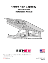
Railcar Ramp
Vertical Hydraulic
Dock Leveler
Installation and Operation Manual
Printed in U.S.A. Publication No. 1134
Copyright 1997 April 1998

iPub. No. 1134 — April 1998
OWNER RESPONSIBILITY
The owner’s responsibilities include the following:
The owner should recognize the inherent danger of the
interface between dock and transport vehicle. The owner
should, therefore, train and instruct operators in the safe
use of dock leveling devices in accordance with informa-
tion provided in Section 4.1.2.
When a transport vehicle is positioned as closely as
practicable to a dock leveling device, there shall be at
least 4" (100 mm) of overlap between the front edge of
the lip and the edge of the floor or sill of the transport
vehicle.
Nameplates, cautions, instructions, and posted warnings
shall not be obscured from the view of operating or
maintenance personnel for whom such warnings are
intended.
Manufacturer’s recommended periodic maintenance and
inspection procedures in effect at date of shipment shall
be followed, and written records of the performance of
these procedures should be kept.
Dock leveling devices that are structurally damaged or
have experienced a sudden loss of support while under
load, such as might occur when a transport vehicle is
pulled out from under the dock leveling device, shall be
removed from service, inspected by the manufacturer’s
authorized representative, and repaired as needed
before being placed back in service.
The manufacturer shall supply replacement nameplates,
caution or instruction labels, and operating and mainte-
nance manuals upon request of the owner. The owner
shall see that all nameplates and caution and instruction
markings or labels are in place and legible and that the
appropriate operating and maintenance manuals are
provided to users.
Modifications or alterations of dock leveling devices shall
be made only with written permission of the original
manufacturer. These changes shall be in conformance
with all applicable provisions of this standard and shall
be at least as safe as the equipment was before modifi-
cation. These changes shall also satisfy all safety rec-
ommendations of the original equipment manufacturer
for the particular application of the dock leveler.
When industrial trucks are driven on and off transport
vehicles during the loading and unloading operation, the
brakes on the transport vehicle shall be applied and
wheel chocks or positive restraints that provide the
equivalent protection of wheel chocks engaged.
NOTE
The MH30 Committee recognizes the devices intended
to secure a transport vehicle to a loading dock by
mechanical means. However, no standards currently
exist for the strength, construction or attachment of the
underride guard on a transport vehicle.* It is therefore
recommended that users of such positive restraint
devices review:
• The means of attachment to the transport vehicle
• The strength of the overall connection
• The proper coordination of the actuation of devices
with any signaling system used
• The need to use wheel chocks
In selecting dock leveling devices, it is important to con-
sider not only present requirements but also future plans
or adverse environments.
* Since ANSI MH30.1-1993 was adopted, the National
Highway Traffic Safety Administration has adopted
standards for the strength, construction, or attachment
of the underride guard on a transport vehicle. See Part
571.232 of the Federal Motor Vehicle Safety Standard.
Nevertheless, it is still important to follow the require-
ments of this note.
(The following responsibilities for owners of loading dock equipment are set forth in the American National
Standard for Safety Performance and Testing of Dock Leveling Services MH30.1-1993 and are repeated here for
the convenience of owners and operators of this equipment.)

Pub. No. 1134 — April 1998 ii
SAFETY SIGNAL WORD DEFINITIONS
Indicates an imminently hazardous situation
which, if not avoided, will result in death or
serious injury. This signal word is to be limited
to the most extreme situations.
Indicates a potentially hazardous situation
which, if not avoided, may result in minor or
moderate injury. Is also used to alert against
unsafe practices.
Indicates a potentially hazardous situation
which, if not avoided, could result in death or
serious injury.
Is used to draw attention to a procedure that
needs to be followed to prevent machine or
property damage.

iii Pub. No. 1134 — April 1998
GENERAL SAFETY WARNINGS
LOCKOUT/TAGOUT PROCEDURES
The Occupational Safety and Health Administration requires that, in addition to posting safety warnings and barricading
the work area and loading docks, the power supply has been locked in the OFF position or disconnected. It is manda-
tory that an approved lockout device is utilized. An example of a lockout device is illustrated. The proper lockout proce-
dure requires that the person responsible for the repairs is the only person who has the ability to remove the lockout
device.
In addition to the lockout device, it is also a requirement to tag the power control in a manner that will clearly note that
repairs are under way and state who is responsible for the lockout condition. Tagout devices have to be constructed
and printed so that exposure to weather conditions or wet and damp locations will not cause the tag to deteriorate or
become unreadable.
RITE-HITE Corporation does not recommend any particular lockout device, but recommends the utilization of an OSHA
approved device (refer to OSHA regulation 1910.147). RITE-HITE Corporation also recommends the review and imple-
mentation of an entire safety program for the Control of Hazardous Energy (Lockout/Tagout). These regulations are
available through OSHA publication 3120.
When working with electrical or electronic con-
trols, make sure that the power source has
been locked out and tagged according to OSHA
regulations and approved local electrical codes.
DO NOT ground welding equipment to any
hydraulic cylinder or electrical components. DO
NOT attach welder ground to leveler platform
when welding lower frame support shims into
position. Damage to bearings or hydraulic
equipment will occur. Attach welder ground to
base frame assembly only.

Pub. No. 1134 — April 1998 iv
TABLE OF CONTENTS
DEFINITIONS . . . . . . . . . . . . . . . . . . . . . . . . . . . . . . . . . . . . . . . . . . . . . . . . . . . . . . . . . . . . . . . . . . . . . . . . . . . . . . . 1
INSTALLATION INSTRUCTIONS . . . . . . . . . . . . . . . . . . . . . . . . . . . . . . . . . . . . . . . . . . . . . . . . . . . . . . . . . . . . . . . 3
OPERATING INSTRUCTIONS . . . . . . . . . . . . . . . . . . . . . . . . . . . . . . . . . . . . . . . . . . . . . . . . . . . . . . . . . . . . . . . . . . 18
OPTIONAL EQUIPMENT . . . . . . . . . . . . . . . . . . . . . . . . . . . . . . . . . . . . . . . . . . . . . . . . . . . . . . . . . . . . . . . . . . . . . . 22
MAINTENANCE . . . . . . . . . . . . . . . . . . . . . . . . . . . . . . . . . . . . . . . . . . . . . . . . . . . . . . . . . . . . . . . . . . . . . . . . . . . . . 24
LUBRICATION . . . . . . . . . . . . . . . . . . . . . . . . . . . . . . . . . . . . . . . . . . . . . . . . . . . . . . . . . . . . . . . . . . . . . . . . . . . . . . 25
TROUBLESHOOTING . . . . . . . . . . . . . . . . . . . . . . . . . . . . . . . . . . . . . . . . . . . . . . . . . . . . . . . . . . . . . . . . . . . . . . . . 26
SCHEMATICS . . . . . . . . . . . . . . . . . . . . . . . . . . . . . . . . . . . . . . . . . . . . . . . . . . . . . . . . . . . . . . . . . . . . . . . . . . . . . . 28
REPLACEMENT PARTS . . . . . . . . . . . . . . . . . . . . . . . . . . . . . . . . . . . . . . . . . . . . . . . . . . . . . . . . . . . . . . . . . . . . . . 34
INTRODUCTION
The purpose of the Railcar Ramp hydraulic leveler is to safely and reliably bridge the gap between the loading dock
and the railcar. This RITE-HITE®dock leveler Model Railcar Ramp is hydraulically operated. There are no
chains/cables to pull or handles to lift. The only energy required of the dock attendant is to push and hold the LOWER
button on the control box allowing the unit to descend to the railcar floor. After loading or unloading is complete, the
dock attendant needs only to push and hold the RAISE button on the control box for the Railcar Ramp hydraulic leveler
to raise back to the vertical stored and locked position. A 1 horsepower unit requiring a 30 amp. circuit delivers
hydraulic oil to a non-regenerative hydraulic system and assures leak-proof operation. The ramp is raised by a 3-1/2"
I.D. hydraulic cylinder. Hydraulic pump/motor and plumbing are mounted under the platform.


Pub. No. 1134 — April 1998 1
LIP
The lip is the extendible portion of the dock leveler which
provides a bridge from the platform to the bed of the box
car. The leveler lip features seamless steel tube lip hinges.
PLATFORM
The platform, along with the lip, provides the main bridge
between the dock and the box car. It is hinged at the
rear of the subframe, and automatically adjusts with the
position of the box car. The platform is constructed in a
four-sided box structure with a bridge bar at the header
cutout. When in the vertical stored position, the platform
is securely held in place by the hydraulic system or by
the maintenance strut. Additional details on the mainte-
nance strut are given later.
END LOAD ARMS
The end load arms provides support in an end load con-
dition when the lip is not used. The major components of
the end load assembly are two ramp support arms, one
on either side of the platform. In an end load condition,
the operator loosens the support arm lock on the plat-
form allowing the ramp support arm to be pulled out. To
secure the ramp support arm at the needed length, the
support arm lock is tightened. When loading or unload-
ing is complete, the support arm lock is loosened and
the ramp support arms are slid back inside the runoff
guards; they can be secured in place by tightening the
support arm lock.
CARRIAGE ASSEMBLY
The carriage assembly attaches the platform to the track
assembly. The carriage assembly consists of the hori-
zontal carriage and a number of horizontal and vertical
rollers to allow smooth movement of the Railcar Ramp
hydraulic leveler along the track assembly.
TRACK ASSEMBLY
The track assembly consists of a ten foot section fur-
nished by RITE-HITE®. The track assembly allows the
carriage assembly to move freely left and right for proper
railcar loading and unloading.
MAIN LIFTING CYLINDER
The main lifting cylinder is a double acting hydraulic piston
of heavy duty construction grade, non-adjustable, with a
3-1/2" diameter piston and a 1-1/2" diameter rod. When
the power unit is energized, the cylinder extends, lifting
the platform.
LIP CYLINDER
The lip cylinder is a single-acting hydraulic piston of
heavy duty construction grade, non-adjustable with a
2-1/2" diameter piston and a 1" diameter rod. When the
power unit is energized, the cylinder extends, lifting the
lip. When power is removed, the lip’s weight compresses
the cylinder, allowing the lip to fall back to the pendant
position.
POWER UNIT
The power unit for the Railcar Ramp hydraulic leveler is
an electro-hydraulic motor which pumps hydraulic fluid to
the ramp lifting cylinder. The power unit package con-
sists of a 1 hp 120V or 240V single phase electric motor,
a 1.35 GPM gear pump, a 1.5 gallon capacity hydraulic
fluid reservoir, and all valving.
NOTE
When adding oil, use only MIL-H-5606 or equal.
VALVE BLOCK ASSEMBLY
The valve block assembly consists of a metal block with
attached valves which control the hydraulics of the
Railcar Ramp.
SAFETY STOP SYSTEM
The hydraulic system has an emergency flow control
stopping valve (velocity fuse) that prevents the leveler
from “free-falling” if a hose should be damaged and
loose pressure. The valve is in line with the hydraulic
hose at the ramp lifting cylinder.
DEFINITIONS

2Pub. No. 1134 — April 1998
MAINTENANCE STRUT
The Railcar Ramp hydraulic leveler is shipped with its own
maintenance strut. This maintenance strut is inserted
between the inside of the platform and the rear curb angle
of the pit. The maintenance strut increases the level of
safety for workers when installing equipment or perform-
ing routine maintenance, and must be used every time
service is being performed on the unit.
SKEWED DECK
The length of deck is a different dimension on the left
side versus the right side to compensate for curve track
applications.
CARRIAGE WINDOWS
Access holes in carriage for weld-on applications which
are installed in pit type applications.
STRAIGHT TRACK
When the railroad track and mounting rail section are
parallel within ±1" over 90° (45' to the left and right of the
door center line).
CURVE TRACK
When the railroad track and mounting rail section are not
within ±1" over 90° (45' to the left and right of the door
center line).
ACTUAL CENTERLINE DIMENSION
The measurement from the top of the dock edge of the
nearest rail, plus 2' 4-1/4".
EFFECTIVE CENTERLINE DIMENSION
The calculated dimension to determine fabrication
requirements of the platform length based upon one
or all of the following: Fixed or movable application,
recessed dimensions, capacities and curve track
application.
CONTINUOUS RAIL APPLICATION
When more than (1) mounting rail section is used. This
type is only applicable with straight track applications.
Please note, continuous rail section must be requested
when the order for the unit is entered. This will ensure
the ends are beveled for field welding.
FIXED APPLICATION
Railcar ramp does not move side to side in mounting rail
section.
MOVEABLE APPLICATION
Railcar ramp moves or slides to the left or right in mount-
ing rail section(s).
EMBEDDED (STANDARD RAIL SECTION)
When the rail section is embedded into concrete at the
top edge of the dock face. This method is shipped stan-
dard with all Railcar Ramp hydraulic leveler applications
and is preferred. Please note, for “F” and “L” capacity
units, this application is required. When these capacities
are used with “existing” applications, the end user is
required to remodel the dock face with an embedded
rail section.
WELD-ON
Option 1
The rail section is welded to a minimum size 15" “C”
channel complying with RITE-HITE®’s specifications.
See Figure 10.
Option 2
The mounting rail section is welded to existing curb steel
that has a vertical leg which measures 5" to 10" in size.
Please note, if replacing an existing Railcar Ramp
hydraulic leveler, an approach plate may be required.

Pub. No. 1134 — April 1998 3
INITIAL INSTALLATION
1. Verify that the rail assembly channel is level,
plumb, and even with the dock floor. If the rail
assembly does not meet specifications, contact the
RITE-HITE Corporation for further instructions.
2. Remove shipping bands and inspect the unit for
damaged or missing parts. If any are noticed, con-
tact the RITE-HITE Corporation.
3. Verify that available voltage and phase is the same
as specified on the hydraulic pump/motor specifica-
tion plate.
4. Make sure that the lifting unit, or picker crane, is
capable of lifting a minimum of 3,000 lbs.
INSTALLATION INSTRUCTIONS
1. Post safety warnings and barricade work
area, at dock level and at ground level, to
prevent unauthorized use of the Railcar
Ramp Leveler before full installation has
been completed.
2. DO NOT REMOVE SAFETY-LOCK PIN until
hydraulic system has been filled and
purged of air. See page 11, “Initial Start-up.”
Follow all electrical LOCKOUT/TAGOUT proce-
dures as stated on page iii of this manual.
1. Be sure to follow these caution notes when
installing your Railcar Ramp Leveler.
2. DO NOT ground welding equipment
to any hydraulic cylinder or electrical
components.
3. DO NOT attach welder ground to leveler
platform when welding on base frame
assembly. Attach welder ground to base
frame assembly only. Damage to bearings
or hydraulic equipment will occur.
4. DO NOT connect green ground lead until
all welding has been completed.
5. Unit is shipped filled with hydraulic oil.
Verify oil level before operating.
6. NOTE – check motor rotation. Jog the
motor until rotation has been determined.
Do Not run the motor in reverse because
this will burn out the motor and hydraulic
pump unit.
7. If a procedure is not clearly defined in this
manual, contact RITE-HITE Corporation at
414-355-2600 before proceeding.

4Pub. No. 1134 — April 1998
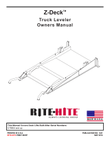
STANDARD EMBEDDED RAIL
1. Using a lift truck or picker crane, attach lifting
device via chain through lifting angles, located
under the platform. See Figures 1 and 2.
2. The Rail Car Ramp leveler fits onto a rail curb angle
that is embedded into the concrete at the edge of
dock with one or both ends of the rail open.
To lift and install the Rail Car Ramp, follow these
steps:
a. Secure chains to the lifting angles under the
platform.
b. From the rail road track side move leveler and
carriage assembly to the end of the rail. Slide
the carriage rollers into the rail. See Figure 3.
c. Move and slide the carriage slowly insuring
leveler does not bind on rail until complete car-
riage and rollers are engaged in the track.
3. Place a bar (1/4" x 2" x 8") or two end stops
(1/4" x 2" x 2") across both ends of the rail insuring
both rails are properly stopped. Weld stops to rail
to keep the leveler from accidentally being pushed
off the rail.
Crane
Lifting Angle
FIGURE 1
Always double check the rigging to make sure
that it is secure and balanced before proceed-
ing with the lift. Never stand under any unit
being lifted.
C
L
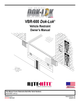
DANGER
DO NOT STAND
ON THIS SIDE OF
DOCK LEVELER!!
LEVELER SWINGS
DOWN TOWARD YOU
CAUTION!
“THIS EQUIPMENT SHOULD NOT BE OPERATED
OR SERVICED EXCEPT BY TRAINED PERSONNEL.
LIKE MANY OTHER PIECES OF EQUIPMENT, IT
CAN CAUSE INJURIES IF IT IS NOT HANDLED
PROPERLY.” FOR ASSISTANCE CONTACT THE
RITE-HITE CORPORATION (414) 355-2600
MILW., WIS. (414) 3552600
BY
HYDRAULIC
DOCK LEVELER
FIGURE 2

Pub. No. 1134 — April 1998 5
Top Of Dock
FIGURE 3
DO NOT REMOVE SAFETY
PIN UNTIL SYSTEM HAS
BEEN PROPERLY FILLED
WITH HYDRAULIC FLUID
(SEE INSTRUCTIONS)
Safety
Restraint
Pin
Rear
Hinge
Frame
Platform
FIGURE 4
The Railcar Ramp hydraulic leveler is held in
the vertical position by a safety restraint pin
located in the lower right hand corner of the
platform assembly. See Figure 4. DO NOT
remove this pin or warning tag until instructed
to do so.

6Pub. No. 1134 — April 1998
WELD-ON TRACK ASSEMBLY
1. Separate the platform from the frame carriage
to make the installation of the Weld-On track
assembly easier. See Figure 5.
2. Place the frame carriage rollers into the track angles
and slide the frame until it is centered on the track
assembly. Clamp the frame carriage to the roller track
assembly to prevent any movement when lifting.
3. With proper overhead lifting equipment, attach the
lifting equipment to the frame carriage and track
assembly. Position on dock face so that the top
edge of the frame carriage assembly is flush and
level with the top of the dock surface. Tack weld
several holes at each end to hold in place before
fully plug welding the roller track assembly. See
Figure 6.
4. After correctly positioning the roller track assembly,
plug weld the outer-most holes before removing the
clamp from the frame carriage, allowing the frame
carriage to be moved laterally (side to side).
5. Move the frame carriage all the way over to one
side of the track. See Figure 7. Plug weld all
exposed holes in the roller track. Move the frame
carriage slowly to the opposite side of the track,
plug welding all holes exposed by the carriage
“windows” as the frame carriage is moved from one
side to the other. Once the frame carriage is all the
way over to the opposite side of what was welded,
plug weld the remaining exposed holes.
Cotter Pin
Hinge Pin
Washer
Platform
Safety Lock
Pin Storage
Hole
Carriage Assembly
FIGURE 5

Pub. No. 1134 — April 1998 7
6. If this is a Weld-On application where the bottom
row of holes will use concrete anchors, use the
roller plate as a drilling template to drill out ALL
anchor holes. Use Rawl “Rawl-Bolt” #6987
0.625 x 6" LG Flat Head concrete anchors (sup-
plied by others). Tighten all anchors to 100 ft. lbs.
torque unless otherwise specified.
7. Weld across the entire length of roller track.
8. Remove all weld spatter and residue from track
angle surfaces and remove all concrete dust and
debris if concrete anchoring was used.
9. Using proper overhead lifting equipment, reattach
the platform to the frame carriage. Extend the ramp
cylinder piston rod and align with the mounting hole
in the lower pivot weldment and install the pivot pin.
See Figures 8 and 9.
Crane
FIGURE 8
FIGURE 6
(Carriage "Windows")
(Carriage "Windows")
FIGURE 7

8Pub. No. 1134 — April 1998
Cotter Pin
Hinge Pin
Washer
Platform
Safety Lock
Pin Storage
Hole
Safety Lock
Carriage Assembly Carriage Assembly
Platform
FIGURE 9

Pub. No. 1134 — April 1998 9
FIXED APPLICATION – WELD-ON/BOLT-ON
For additional information on Fixed Application Installation
Instructions, see the detail drawings provided with the
Railcar Ramp hydraulic leveler.
1. Locate the frame assembly at the 0.25" below dock
edges dimension. Tack weld in place. See Figure 10.
2. Weld all plug welds and across the top surface, and
along the ends and bottom. See Figures 10 and 11.
3. With proper overhead lifting equipment, attach a
lifting clamp to the extended lip, or use lifting
angles on the underside of the platform.
4. Using proper overhead lifting equipment, reattach
the platform to the frame carriage. Extend the ramp
cylinder piston rod and align with the mounting hole
in the lower pivot weldment and install the pivot pin.
See Figures 8 and 9.
Weld-On Style Rear Frame
1.38
4.25 Full Weld
All Holes
Mounting Channel
Flatness 0.125"
Vertical Straightness
0.125" Over Entire Length
Pit Length 0.25"
Over Entire Width
+
-
NOTE: DO NOT INSTALL
If Pit And Angle Tolerances
Are Not As Shown.
Hinge Plate Is Easiest To Install
If The Ends Are Secured First.
Secure The Center Next And Stagger
The Weld Sequence Between The
Right And Left Of The Centerline.
Building
Wall
24"
Minimum
Cotter Pin
Hinge Pin
Washer
Platform
Safety Lock
Pin Storage
Hole
FIGURE 10
0.25"
Remove All Welding
Residue Break All Sharp
Corners After Welding
1.688
10.00
+.031
-.000
.25
.25
Full Weld
27 Places
.25
Both Ends
.25
3-5
Dimensions Shown In Inches
Unless Otherwise Specified.
FIGURE 11

10 Pub. No. 1134 — April 1998
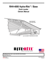
#10 Gage #10 Gage
#10 Gage
#10 Gage
480V 3 Phase
Incoming Power From Customers
Fused Disconnect (Supplied By Others)
(Wire Size Per Chart) Hydraulic
Control Box
G
3
L2
2
L1L2 L3
T1T2T3
T1*
T2*
G*
3**
L2**
2**
T1
T2
L2
2
3
G
(*) Min #8 Gage Wire
(** ) Min #14 Gage Wire Field Wiring
(By Others)
Wire Nut
Conn. (Typ.)
Wire Nut
Conn. (Typ.)
To Motor
J-BOX
To Sol. Coil
“RAMP”
To Sol. Coil
“LIP”
Junction Box (On Pit Floor Or On
Remote Power Unit Platform.) (Supplied
And Installed By Others.)
BLK
YLW
Typical Single Phase
23
G
Incoming Power From Customers
Fused Disconnect (Supplied By Others)
(Wire Size Per Chart) Hydraulic
Control Box
G
3
X2
2X1
1X1
X2
2L1
1L1
L2
2
L1L2 L3
T1 T2 T3
T1*
T2*
T3*
G*
3**
X2**
2**
T1
T2
T3
X2
2
3
G
(*) Min #10 Gage Wire
(** ) Min #14 Gage Wire Field Wiring
(By Others)
To Motor
J-BOX
To Sol. Coil
“RAMP”
To Sol. Coil
“LIP”
Junction Box (On Pit Floor Or On
Remote Power Unit Platform.) (Supplied
And Installed By Others.)
BLK
YLW
Typical Three Phase
Rigid Conduit
(By Others)
Hirschmann
Conn. Cords
Solenoid
Control
Valve
Hydraulic Power Unit
Motor
Junction
Box
Hydraulic
Control Box
(By RITE-HITE®)
SO Cord (Supplied By RITE-HITE®)
Fused Power
Disconnect
(Required)
(By Others)
One Leveler
Per Overload
Protection
Device. [Ref.
N.E.C. 1990
Para. 430-110
(B)(C)] Consult
Local Code
23
G
120V 1 Phase
240V 1 Phase
0-100'
#8 Gage
#10 Gage
240V 3 Phase
100-200' 200'+
Wire Size Chart
Voltage
&
Phase
#10 Gage
#8 Gage
#10 Gage
#10 Gage
#6 Gage
#8 Gage
Distance From Door To
Power Disconnect
FIGURE 12 — WIRING DIAGRAMS AI-1605

Pub. No. 1134 — April 1998 11
CONTROL BOX INSTALLATION
1. Install the control box as indicated in Figure 13.
2. Connect wiring to the control panel and the Railcar
Ramp hydraulic leveler as indicated in Figure 12.
3. Install junction box or connect main power.
4. Manually extend the Ramp Cylinder until the cylin-
der rod clevis aligns with the embedded frame
channel clevis. Loosen the locking bolt on the cylin-
der rod clevis if it is required to adjust the cylinder
clevis either higher or lower for alignment. Rotate
the clevis end to adjust. See Figure 17.
NOTE
When the leveler is in the vertical stored position
there should be approximately .062" minimum clear-
ance between the hydraulic cylinder rod and the
notch in the rear header assembly. See Figure 15.
There should be a 3" offset to assure a safe vertical
storage position. See Figure 16.
5. Insert the clevis pin. Secure the clevis pin with the
thrust washers and cotter keys.
Post safety warnings and barricade work area, at
dock level and at ground level to prevent unau-
thorized use of the RCR during maintenance/
service.
Make sure that the electrical power has been
locked out and the power source tagged before
proceeding with the installation.
Junction Box
Control
Box
Dock
Floor
24"
48"
6"
FIGURE 13
System Relief
Sight Glass
Shuttle Valve
Fill Port
Breather
IMPORTANT - CHECK OIL
LEVEL BEFORE MAKING
ANY ADJUSTMENTS - ADD
MIL-H5606 HYDRAULIC
FLUID ONLY.
FIGURE 14 — HYDRAULIC OIL FILLING
When working with electrical or electronic
controls, make sure that the power source has
been locked out and tagged according to OSHA
regulations and approved local electrical codes.

12 Pub. No. 1134 — April 1998
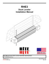
HYDRAULIC SYSTEM START-UP
1. The leveler ships with oil stored within the hydraulic
reservoir.
Locate the yellow plastic plug which is inserted in the
breather port. Remove and discard this plug ONLY
after unit has been installed and is vertically stored.
2. Install the breather assembly into the breather port.
See Figure 18.
Deck
Rear Header Cylinder Rod
0.062 Min.
(Viewed From Above)
FIGURE 15 — CYLINDER ROD CLEARANCE
3"
Service
Strut
Stored
Position
Service
Strut
Service
Position
FIGURE 16 — VERTICAL STORAGE POSITION
FIGURE 17 — CLEVIS ADJUSTMENT
DO NOT operate leveler with anyone standing
in front of the leveler.
This equipment should not be operated or ser-
viced except by trained personnel.
Keep away from hinge when operating leveler.

Pub. No. 1134 — April 1998 13
RAMP
LIP5
CB
BASE
10
PT
CAUTION!
“THIS EQUIPMENT SHOULD NOT BE OPERATED
OR SERVICED EXCEPT BY TRAINED PERSONNEL.
LIKE MANY OTHER PIECES OF EQUIPMENT, IT
CAN CAUSE INJURIES IF IT IS NOT HANDLED
PROPERLY.” FOR ASSISTANCE CONTACT THE
RITE-HITE CORPORATION (414) 355-2600
A
AB
B
VIEW A-A
TOP VIEW
BOTTOM VIEW
Pressure
Tank
Lip Three Way Valve
Ramp Four Way Valve
Counterbalance Valve
56303
Lip Out
Relief Valve
(Fixed)
6680
Main Valve
Block Assembly
(55299)
Lip Fall
Pressure
Compensated
Flow Control
55186
Three Way Two Position
Lip Solenoid Valve
(55261 Coil)
Lip Fall
Relief Valve
55253
Counterbalance
Valve
55184
Four Way Two Position
Lip Solenoid Valve
(55261 Coil)
Lip Out
Relief Valve
Cyl. Rod
55146
Shuttle
Valve
CORPORATION
MILWAUKEE, WI
(414) 355-2600
PART #6624
55024
Breather
Plug
VIEW B-B
C1
55311
Check Valve
70 PSI
(Optional
55313 90 PSI)
Lip (Base)
System
Relief
IMPORTANT - CHECK OIL
LEVEL BEFORE MAKING
ANY ADJUSTMENTS - ADD
MIL-H5606 HYDRAULIC
FLUID ONLY.
FIGURE 18 — HYDRAULIC VALVE ADJUSTMENT SEE AI-1757
Gap Gap
Locknut
Cap Nut
O-ring
(In Recess)
Adjusting Screw
Gaps Must Be Equal
FIGURE 19

14 Pub. No. 1134 — April 1998
3. From dock level, push the leveler against the safety
lock pin.
4. Have an assistant press and hold the RAISE button
on the control box until the platform moves back
towards the vertical stored position. This indicates
that the main cylinder has been filled with oil.
Continue to hold the RAISE button until the lip fully
extends, indicating that the lip cylinder has been
filled with oil, and release the RAISE button.
5. Inspect the sight glass on the hydraulic reservoir.
See Figure 14. The oil level should be visible. If
not, temporarily install a 45°street elbow and using
a funnel, fill the reservoir with oil until the level is
visible in the sight glass. Use only MIL-H-5606.
6. Press and hold the RAISE button until the Lip
Cylinder fully extends.
7. Check the fluid level in the reservoir. Add more
hydraulic fluid until the proper level is noted at
the sight glass. Do not overfill the reservoir, fluid
will leak out of the breather port when the unit is
lowered into the service position, if overfilled.
See Figure 14.
AIR PURGING PROCEDURE
1. Open overhead door.
2. Locate the Service Strut device stored under the
leveler body. See Figures 16 and 20. Insert the
Service Strut in the proper position.
3. Remove the Safety Lock Pin and indicator tag.
Install the Safety Lock Pin and indicator tag through
the hole on the leveler frame and secure with the
cotter key, for storage. See Figure 9.
4. Remove and store Service Strut device.
5. Press and hold the LOWER button on the control
panel until the leveler is at about a 30°angle. Return
the leveler to the normal raised/stored position.
6. Repeat Step 5 five more times, each time allowing
the platform to drop slightly lower before raising it
up again.
If the main cylinder does not begin to extend
within five seconds release the RAISE button,
the pump/motor is running in reverse. Review
the electrical wiring diagram and reverse motor
leads (3 phase only).
Make sure that the electrical power has been
locked out and the power source tagged before
proceeding with the installation.
Post safety warnings and barricade work area, at
dock level and at ground level to prevent unau-
thorized use of the RCR during maintenance/
service.
DO NOT operate leveler with anyone standing
in front of the leveler.
This equipment should not be operated or ser-
viced except by trained personnel.
Keep away from hinge when operating leveler.
/