Page is loading ...

TECHNICAL CATALOG
32M-06003-05
MAXON SMARTLINK® MRV
INTELLIGENT MICRO-RATIO® VALVE SERIES

MAXON SMARTLINK® MRV
32M-06003-05 2 E - m -02/22
TABLE OF CONTENTS
Product description ............................................................................................................................................. 3
Features and benefits ............................................................................................................................................. 4
Applications ............................................................................................................................................. 4
Model numbers ............................................................................................................................................. 5
Model numbers ............................................................................................................................................. 5
Butterfly valves ............................................................................................................................. 5
Ball valves ....................................................................................................................................... 5
Control Actuator ........................................................................................................................... 8
Spare Actuator .............................................................................................................................. 8
Control Interface .......................................................................................................................... 10
User Display ................................................................................................................................... 10
Design and Application Details ............................................................................................................................................. 12
Specifications of SMARTLINK® MRV ............................................................................................................................................. 13
System specifications ................................................................................................................ 13
Component specifications ....................................................................................................... 14
Valve body capacities - butterfly valves ............................................................................. 15
Valve body capacities - ball valves ....................................................................................... 17
Materials of construction ............................................................................................................................................. 18
Butterfly valves ............................................................................................................................. 18
Ball valves ....................................................................................................................................... 21
Dimensions ............................................................................................................................................. 22
Butterfly valves ............................................................................................................................. 22
Ball valves ....................................................................................................................................... 29
Control Actuator ........................................................................................................................... 35
Control Interface .......................................................................................................................... 37
Interface Panels ........................................................................................................................... 38
Installation Instructions ............................................................................................................................................. 42
Safety requirements ................................................................................................................... 42
SMARTLINK® MRV components ............................................................................................ 44
Optional components ................................................................................................................ 45
Optional SMARTLINK® MRV Interface Panel Assemblies ............................................ 45
Mechanical Installation ............................................................................................................ 46
Electrical Installation ................................................................................................................. 48
Operating Instructions ............................................................................................................................................. 55
Control Interface operation ..................................................................................................... 55
User Display Operation ............................................................................................................. 56
Wiring Checkout .......................................................................................................................... 56
Operational Checkout ............................................................................................................... 57
Using the Control Interface for Command Entry ........................................................... 58
System Configuration ................................................................................................................ 59
10-Point System Commissioning ......................................................................................... 59
19-Point System Commissioning ......................................................................................... 59
Custom Start-up Positions ...................................................................................................... 60
Commissioning Procedure with Control Interface ........................................................ 61
Commissioning Procedure with User Display ................................................................. 62
Unit Locking and Passcode Entry ........................................................................................ 63
Manual Operation ....................................................................................................................... 64
Power Loss with Large Valves (>12”) ................................................................................... 64
Troubleshooting and Alarms/Faults ................................................................................... 65
Maintenance instructions ............................................................................................................................................. 66
Actuator replacement ................................................................................................................ 66
SMARTLINK® MRV Reference Tables ............................................................................................................................................. 68

MAXON SMARTLINK® MRV
E - m - 02/22 3 32M-06003-05
PRODUCT DESCRIPTION
The MAXON SMARTLINK® MICRO-RATIO® Valve (MRV) is
an industrial parallel positioning system for combustion
applications providing a high degree of precision,
repeatability, tamper resistance, and durability. In
addition, SMARTLINK® MRV interfaces with all burner
management and flame safety systems, simplifying
retrofit applications. The system is simple to set-up and
does not require a personal computer in the field for
commissioning.
SMARTLINK® MRV includes 1, 2, 3, or 4 Valve Actuators
directly coupled to flow control valves, and a Control
Interface unit which serves as a commissioning interface
and “gateway” between the Valve Actuators and the user’s
process controller, PLC, or distributed control system
(DCS).
The SMARTLINK® Valve Actuator design is an industrial,
factory-calibrated assembly. It incorporates a precision,
planetary gear-head with integrated position feedback
and a stepper motor for continuous duty control of various
valves. Each valve actuator is powered by 24VDC and
includes a digital position control loop and a digital
interface that ensures reliable operation even in
electrically noisy environments. The small footprint,
weatherproof enclosure and Class I, Division 2 approvals,
and superior position control performance make this
product a high performance, cheaper alternative to
pneumatic equipment.
The SMARTLINK® MRV Control Interface is a DIN rail-
mounted digital hub that electronically “links” and
synchronizes valve movement for precision air/fuel ratio
control. Front-mounted switches and indicators are
provided for displaying alarms, system configuration, and
valve characterization. The Control Interface also provides
a precision 4-20 mA firing rate feedback signal. Optional
equipment includes MAXON Relay Input and Output
Interfaces, a User Display, universal power supply, factory-
wired panel assemblies, and several NEMA 4X enclosures.
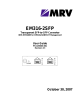
SMARTLINK® gas butterfly valve (left), air butterfly valve (center) and ball valve (right)
assemblies
Inside view of SMARTLINK®
Actuator, showing planetary
gearheads
Control Interface with optional
User Display, Relay Input, Out-
put and Network Interfaces in
pre-wired panel assembly

MAXON SMARTLINK® MRV
32M-06003-05 4 E - m -02/22
FEATURES AND BENEFITS
• Precise and repeatable flow control optimizes fuel
efficiency, enables accurate temperature control and
lowers burner emissions.
• SMARTLINK® MRV is an electronic parallel position-
ing system for air/fuel ratio control; for use in indus-
trial applications providing a high degree of
precision, repeatability and durability.
• Synchronous control of up to four valves with con-
ventional signal from the user’s process controller.
• Direct coupled valve and actuator assembly includes
weatherproof housing with integrated position feed-
back and heavy duty planetary gearheads for reli-
able, long life operation.
• Compact, robust design mounts in any orientation.
• Each SMARTLINK® Valve is adjustable to 0.1 degrees
accuracy.
• UL and CE approved electronics and software for air-
fuel ratio control.
• Stores a 22 point user-customized profile for each
valve.
• Factory Mutual (FM) approved as non-incendive for
Hazardous Locations Class I, Division 2 and ATEX,
IEC Ex and KC approval; standard actuator is also
NEMA 4X, Class II, Division 2 approved.
• Maintenance-free operation; no lubrication
required. No valve packing to adjust.
• Electronic passcode protection eliminates valve pro-
file tampering.
• Simple set-up; no PC required.
• Standby, purge and light off positions can be defined
independent of valve profiles.
APPLICATIONS
SMARTLINK® MRV is designed for precision control of
industrial combustion systems, boiler combustion
systems, and related heating process flows. The rugged
industrial package adds value to many heating and
manufacturing processes by providing highly accurate,
characterizable flow control with enhanced, digital
intelligence.
Typical applications include:
• Simple burner ratio controls
• Low NOx and low CO burner controls
• Control of combustion systems on processes sensi-
tive to products of combustion
• Control of complex burners with staging or flue gas
recirculation
• Precise control of process flows like feed water,
atmosphere gases, and even product feeds
• Accurate flow control of metered processes and pro-
cess heaters for liquids and gases
APPROVALS
FM Nonincendive for Class I, Division 2: Groups A,B,C,D,T4 (when provided with specialized NEMA 4X enclosures)
(valve actuator also Class II, Division 2; Groups E, F, G)
FM
(ATEX)
II 3 G Ex nA nC IIC T4 Ta=-40C to +70C; IP66 when components mounted in enclosure
(valve actuator is II 3 G Ex nA nC IIC T4 Ta=-40C to +70C; IP66 and II 3 D Ex tC IIIC T135C Dc IP66).
Note: Only the Actuators, Control Interface, Network Interface, User Display, 24V Relay Input Interface, Relay
Output Interface are ATEX approved; FM09ATEX0062X.
FM
(UKCA)
II 3 G Ex nA nC IIC T4 Ta=-40C to +70C; IP66 when components mounted in enclosure
(valve actuator is II 3 G Ex nA nC IIC T4 Ta=-40C to +70C; IP66 and II 3 D Ex tC IIIC T135C Dc IP66).
Note: Only the Actuators, Control Interface, Network Interface, User Display, 24V Relay Input Interface, Relay
Output Interface are approved; FM21UKEX0098X.
IEC Ex
Ex nA nC IIC T4 -40°C ≤ Ta ≤ 70°C Gc, Ex tC IIIC T135C Dc; Interface - IP54; Actuator - IP65; Meter - IP66;
Note: Only the Actuators, Control Interface, Network Interface, User Display, 24V Relay Input Interface, Relay
Output Interface are IEC Ex approved.
UL UL (US & Canadian): Air Fuel Ratio System and Limit Controls (UL353), Class 2 Software (UL 1998)
Temperature-Indicating and Regulating Equipment (CSA C22.2 No. 24-93)
CE
(GAR)
CE Gas Appliance Directive: Gas-Air Ratio Controller, Class C Software (BS EN 12067-2, BS EN298,
ISO 253552-1)
CE EMC Directive: Electromagnetic Immunity and Emissions (BS EN61000)
CE Low Voltage Directive: Electrical Safety (BS EN61010-1)
KTL/KC Ex nA nC IIC T4, Ex tc IIIC T135C IP65
CCC
Approvals
Actuators: Ex nA nC IIC T4 Gc; Ex tD A22 IP66 T135°C; GB 3836.1, GB 3836.8, GB 12476.1, GB 12476.5;
Panel Devices: Ex nA nC IIC T4 Gc; GB 3836.1, GB 3836.8;
Certification No: GYB21.1433X
UKCA
(GAR)
CE Gas Appliance Directive: Gas-Air Ratio Controller, Class C Software (BS EN 12067-2, ISO 253552-1)
CE EMC Directive: Electromagnetic Immunity and Emissions (BS EN61000)
CE Low Voltage Directive: Electrical Safety (BS EN61010-1)

MAXON SMARTLINK® MRV
E - m - 02/22 5 32M-06003-05
MODEL NUMBERS
Butterfly valves
The model number shown on the valve nameplate can
accurately identify every MAXON SMARTLINK® MRV
Butterfly Valve. The example below shows a typical
SMARTLINK® MRV Butterfly Valve model number, along
with the available choices for each item represented in the
model number. The first three choices determine the
valve's configured item number. The next eight characters
in the model number identify valve body and actuator
options.
Ball valves
The model number shown on the valve nameplate can
accurately identify every MAXON SMARTLINK® MRV Ball
Valve. The example below shows a typical SMARTLINK®
MRV Ball Valve model number, along with the available
choices for each item represented in the model number.
The first three choices determine the valve's configured
item number. The next eight characters in the model
number identify valve body and actuator options.
Configured Item Number Valve Body Actuator
Valve
Size
Flow
Capacity
Series
Body
Connection
Body
Seals
Body
Material
Body
Internals
Torque
Rating
Software
Version
Language
Valve
Number
0100 S SRCV - A A 1 1 - 1 1E A 0
Size
0100 - 1"
0125 - 1.25"
0150 - 1.5"
0200 - 2"
0250 - 2.5"
0300 - 3"
0400 - 4"
0600 - 6"
0800 - 8"
1000 - 10"
1200 - 12"
1400 - 14"
1600 - 16"
Flow Capacity
S - Standard
Series
SRCV - SMARTLINK® MRV
Butterfly Valve
Body Connection
A - ANSI Flange
M - "M" Style Flange
X - Special
* - Actuator Only
Body Seals
A - Buna-N
B - Viton
X - Special
* - Actuator Only
Body Material
1 - Cast Iron
2 - Carbon Steel
3 - Brass
5 - Stainless Steel
X - Special
* - Actuator Only
Body Internals
1 - Trim Package 1
2 - Trim Package 1, Oxy Clean
5 - Trim Package 2
6 - Trim Package 2, Oxy Clean
X - Special
* - Actuator Only
Torque Rating
1 - 33.9 N.m
X - Special
* - Valve Body Only
Software Version [1]
1E - Standard software
** - Valve Body Only
Language
A - English
X - Special
* - Valve Body Only
Valve Number
0 - Valve 0
1 - Valve 1
2 - Valve 2
3 - Valve 3
4 - Spare Actuator
[1] The latest version is the default.
Trim Package Options and Typical Materials:
1 - 300 Series Stainless Steel stem, 300 Series Stainless Steel disc and Bronze bushings
2 - 300 Series Stainless Steel stem, 300 Series Stainless Steel disc and PEEK bushings

MAXON SMARTLINK® MRV
32M-06003-05 6 E - m -02/22
Configured Item Number Valve Body Actuator
Valve
Size
Flow
Capacity
Series
Body
Connection
Body Seals
& Packing
Body
Material
Body
Internals
Torque
Rating
Software
Version
Language
Valve
Number
0100 7 SRBV - B E 2 1 - 1 1E A 0
Size
0050 - .5"
0075 - .75"
0100 - 1"
0125 - 1.25"
0150 - 1.5"
0200 - 2"
Flow Capacity
1 - 1/32" Slot
2 - 1/16" Slot
3 - 1/8" Slot
4 - 3/16" Slot
5 - 1/4" Slot
6 - 30° V
7 - 60° V
8 - 90° V
9 - Round Port
Series
SRBV - SMARTLINK® MRV Ball Valve
Body Connection
A - ANSI Flanged 150#
B - ANSI Threaded
X - Special (see note 1)
* - Actuator Only
Body Seals & Packing
E - Teflon
X - Special (see note 1)
* - Actuator Only
Body Material
2 - Carbon Steel
5 - Stainless Steel
X - Special (see note 1)
* - Actuator Only
Body Internals
1 - Trim Package 1
X - Special (see note 1)
* - Actuator Only
Torque Rating
1 - 33.9 N.m
X - Special
* - Valve Body Only
Software Version (see note 2)
1E - Standard software
** - Valve Body Only
Language
A - English
X - Special
* - Valve Body Only
Valve Number
0 - Valve 0
1 - Valve 1
2 - Valve 2
3 - Valve 3
4 - Spare Actuator
Note 1: Please see page 7 for all available ball valve options. These will require a special configuration.
Note 2: The latest version is the default.
Trim Package Options and Typical Materials:
1 - 300 Series Stainless Steel Ball, 300 Series Stainless Steel Stem and Teflon Seat Rings

MAXON SMARTLINK® MRV
E - m - 02/22 7 32M-06003-05
Additional Ball Valve Options for Special Configuration
Body Connection
Flat-Faced Flanged
Butt Weld
Extended Butt Weld
Clamp Ends
Groove Ends
Socket Weld
Extended Socket Weld
Tube Ends
300# RF Flanged
600# RF Flanged
Body Seals & Packing
Body Seals
Graphite
Kel-F
Peek
RPTFE
Carbon-Filled RPTFE
UHMWPE
Viton
Packing
Graphite
RPTFE
Carbon-Filled RPTFE
Thrust Washer
Graphite
Hostaflon
Kel-F
Peek
RPTFE
Carbon-Filled RPTFE
UHMWPE
Body Material
Duplex
400 SS
Alloy 20
Monel
Bronze
Hastelloy c
CF8
Titanium
Body Internals
Stem & Ball
Duplex
400 SS
Alloy 20
Monel
Bronze
Hastelloy c
CF8
Titanium
Seat Rings
PFA
Delrin
Hostaflon
Kel-F
Peek
RPTFE
Carbon-Filled RPTFE

MAXON SMARTLINK® MRV
32M-06003-05 8 E - m -02/22
Control Actuator
The model number shown on the actuator nameplate can
accurately identify every MAXON SMARTLINK® MRV
Control Actuator. The example below shows a typical
SMARTLINK® MRV Control Actuator model number, along
with the available choices for each item represented in the
model number. The first choice determines the actuator's
configured item number. The next six choices in the model
number identify the connection and actuator options.
[1] The latest version is the default.
Spare Actuator
The model number shown on the actuator nameplate can
accurately identify every MAXON SMARTLINK® MRV Spare
Actuator. The example below shows a typical SMARTLINK®
MRV Spare Actuator model number, along with the
available choices for each item represented in the model
number. The first choice determines the actuator's
configured item number. The next five choices in the
model number identify the connection and actuator
options.
Configured Item Number
Series
Connection
Torque
Rating
Software
Version
Language
Valve
Number
Rotation
SR CA - K1 - 1 1E A - 0 - 2
Series
SR CA - SMARTLINK® MRV
Control Actuator
Connection
K1 - 1/2" Keyed Output Shaft
L1 - Linkage Arm
S1 - 1/2" Square Output Shaft
S2 - 3/4" Square Output Shaft
Torque Rating
1 - 33.9 N.m
X - Special
Software Version [1]
1E - Standard software
Language
A - English
X - Special
Valve Number
0 - Valve 0
1 - Valve 1
2 - Valve 2
3 - Valve 3
Rotation
1 - Clockwise
2 - Counter-clockwise
1) Clockwise rotation
2) Counter-clockwise
rotation
Control Actuator Rotation
1
2

MAXON SMARTLINK® MRV
E - m - 02/22 9 32M-06003-05
Configured Item Number Actuator
Series
Torque
Rating
Software
Version
Language
Valve
Number
Rotation
SR SA - 1 1E A - 4 - 2
Series
SR SA - SMARTLINK® MRV
Spare Actuator
Torque Rating
1 - 33.9 N.m
X - Special
Software Version [2]
1E - Standard software
Language
A - English
X - Special
Valve Number
4 - Spare Actuator
Rotation [1]
1 - Clockwise
2 - Counter-clockwise
[1] The correct rotation must be specified. (See drawing on page 8.)
a. Butterfly Valves are always supplied in a counter-clockwise rotation.
b. Ball Valves are always supplied in a counter-clockwise rotation.
c. Control Actuators are customer-specific and rotation must be obtained from the actuator this spare is intended to
replace.
[2] The latest version is the default.

MAXON SMARTLINK® MRV
32M-06003-05 10 E - m -02/22
Control Interface
The model number shown on the control interface
nameplate can accurately identify every MAXON
SMARTLINK® MRV Control Interface. The example below
shows a typical SMARTLINK® MRV Control Interface model
number, along with the available choices for each item
represented in the model number. The first four characters
determine the Control Interface's configured item number.
The next 11 characters in the model number identify the
assembly options.
User Display
The model number shown on the user display nameplate
can accurately identify every MAXON SMARTLINK® MRV
User Display. The example below shows a typical
SMARTLINK® MRV User Display model number, along with
the available choices for each item represented in the
model number. The first choice determines the user
display's configured item number. The next two choices in
the model number identify the user display options.
Configured
Item # Assembly Options
Series
Software
Version
Language
Enclosure
User Display
Interface
Panel/Plate
Power
Supply
Network
Interface
Relay Input
Interface
Relay Output
Interface
Rail
Assemblies
Valve Count
SR CI 1E A 2 - 1 A 1 - 1 B 1 1 2
Series
SR CI - SMARTLINK® MRV Control Interface
Software Version [3]
1E - Standard software
Language
A - English
X - Special
Enclosure
0 - None
1 - 24x20x8, NEMA 4, Window
2 - 24x20x8, NEMA 4/4X, SS304 (1.4301), Window
3 - 24x20x8, NEMA 4/4X, SS316, Window
4 - 20x16x8, NEMA 4, Window
5 - 20x16x8, NEMA 4/4X, SS304 (1.4301), Window
6 - 20x16x8, NEMA 4/4X, SS316, Window
7 - 20x16x8, NEMA 4, No Window
8 - 20x16x8, NEMA 4/4X, SS304 (1.4301), No Window
9 - 20x16x8, NEMA 4/4X, SS316, No Window
X - Special
User Display [1]
0 - None
1 - Mounted Inside Enclosure
2 - Mounted Outside Enclosure
3 - Mounted Outside Enclosure w/
dust cover
Interface Panel/Plate
0 - None
A - 24x20 Plate, prewired
B - 24x20 316SS Plate, prewired
C - 20x16 Plate, prewired
D - 20x16 316SS Plate, prewired
X - Special
Power Supply
0 - None
1 - 24VDC
X - Special
* - Included w/Interface Panel
Network Interface
0 - None
1 - Yes
* - Included w/Interface Panel
Relay Input Interface [2]
0 - None
A - 24 VDC
B - 120 VAC
C - 230 VAC
Relay Output Interface
0 - None
1 - Yes
* - Included w/Interface Panel
Rail Assemblies
0 - None
1 - Control Rail Assembly
2 - Control Rail and Terminal
Block Assembly
* - Both included w/Interface
Panel
Valve Count
2 - Two Valve System
3 - Three Valve System
4 - Four Valve System
[1] Mounting on outside of enclosure can only be chosen for a non-window enclosure
[2] One option must be chosen when an Interface Panel/Plate is specified
[3] The latest version is the default.

MAXON SMARTLINK® MRV
E - m - 02/22 11 32M-06003-05
[1] The latest version is the default.
Configured Item Number Options
Series
Software
Version
Language
SR UD - 1E A
Series
SR UD - SMARTLINK® MRV
User Display
Software Version [1]
1E - Standard software
Language
A - English
B - Dutch
C - French
D - German
X - Special

MAXON SMARTLINK® MRV
32M-06003-05 12 E - m -02/22
DESIGN AND APPLICATION DETAILS
Principle of Operation
Tthe SMARTLINK® MRV System synchronously positions 1,
2, 3, or 4 valves with 0.1-degree precision and
repeatability. During ignition sequencing, SMARTLINK®
works with the user’s burner management system to drive
the system to user-defined standby, purge, and light-off
positions. After burner ignition, the user’s process (or
temperature) controller drives SMARTLINK® MRV with a 4-
20 mA firing rate command.
The Valve Actuators perform a high-speed control loop to
achieve their position setpoints without overshoot. Valve
positions are continuously transmitted digitally by the
valve actuator over the communications network to the
control interface for verification of proper valve position.
The control interface also provides a 4-20 mA output
signal that represents actual burner firing rate for process
monitoring. This 4-20 mA output is also used to indicate
the actual position of the valve selected during the
commissioning process.
The Control Interface stores a 22 point, user-
commissioned position profile for each valve and
translates the firing rate command into synchronized,
digital position commands that are sent to the Valve
Actuators over a dedicated communications network.
The Control Interface also includes a set of switches and
indicators to allow the following functions:
1)Customize the position profile and commission each
valve for precision burner tuning
2)Display the operating mode of the system and indicate
alarm/fault codes
3)Display and change system operating parameters (such
as loss of signal operation and valve speed)
4)Electronically lock the device to prevent tampering
5)Locally control burner firing rate in a manual mode
An optional User Display with a 4-line x 20-character LCD
is available to easily commission the system locally or
hundreds of feet away near the burner or field
instrumentation. The User Display shows all alarm and
fault conditions (as text messages), time stamps the last 6
shutdown events, performs system/valve maintenance
functions, stores up to 5 system profiles, and restores the
system profile if the Control Interface is replaced.
Notes:
1. Non-shaded blocks indicate optional MAXON-supplied equipment
2. Shaded blocks indicate SMARTLINK® MRV required components
SMARTLINK
MRV
Control
Interface
(CI)
24VDC
Power
Supply
SMARTLINK
Relay Input
Interface
(RII)
I/O Terminal Blocks
4-20 m A Ter minal Block
Firing Rate
Firing Rate Feedback
To/From User’s
Process Controller
To/From User’s
Burner Management
AC Power
SMARTLINK
Valve A ctuator #0
SMARTLINK
Valve A ctuator #1
SMARTLINK
Valve A ctuaor #2
SMARTLINK
Valve A ctuator #3
SMARTLINK
User Display
SMARTLINK
Network
Interface
(NI)
SMARTLINK
Relay Output
Interface
(ROI)
SMARTLINK
Fut ure Field Device
VAC Terminals
SMARTLINK
Local User
Display
Circuit
Breaker

MAXON SMARTLINK® MRV
E - m - 02/22 13 32M-06003-05
SPECIFICATIONS OF SMARTLINK® MRV
System specifications
SMARTLINK® MRV System Specifications
(For all Interface Panel configurations with factory-wired relay interface modules and power supply)
Position Accuracy 0.1 degrees (measured on the valve actuator shaft)
Number of Valves 1, 2, 3, or 4
Valve Commissioning Profile 22 field-adjustable positions for each valve including individual standby, purge and
light-off positions
Firing Rate Command 4-20 mA isolated input; 4.8V burden @ 20 mA
Firing Rate Feedback 4-20 mA isolated output; 400 ohm max load
Power 24 VDC universal power supply; provides 24 VDC output to all system components
24 VDC within components
1 valve system: 36 W max
2 valve system: 61 W max
3 valve system: 90 W max
4 valve system: 118 W max
Optional power supply 120-230 VAC provides 24 VDC to system
Low to High Fire Modulation Speed 20, 40, or 60 seconds (user-selectable)
Temperature Range (Ambient) All components (except user display): -40°C to 70°C
Enclosure Ratings NEMA 4X, IP66 (valve actuator)
NEMA 4/4X, IP66 (Optional MAXON-supplied enclosures with rail mounted compo-
nents. See page 14 for individual component ratings)
Relay Outputs Form A (N.O.), Dry Contacts
Contact Ratings: 250VAC/DC @ 12 A
Relay Inputs 120VAC, 230VAC, or 24VDC solid-state

MAXON SMARTLINK® MRV
32M-06003-05 14 E - m -02/22
Component specifications
SMARTLINK® MRV Component Specifications
Control Interface
Power Input 24VDC, 0.1 A
Firing Rate Command 4-20 mA isolated input; 4.8V burden @ 20 mA
Spare Current Input 4-20 mA isolated input; 4.8V burden @ 20 mA
Firing Rate Feedback 4-20 mA isolated input: 40 Ohm max load
Relay Driver Outputs Open collector, 30 VDC & 100 mA (max)
Digital Inputs 5-24VDC @ 10 mA (max)
Wiring Terminals Keyed, plug-type screw terminals; Terminals accept 14-24 gauge wire
Enclosure 25 mm W x 118 mm H x 97 mm D DIN rail-mounted, NEMA 1, IP20
Relay Output Interface
Electromechanical Output Relays (6) Dry Contacts: Form A (normally-open)
Max Contact Voltage: 250 VAC/DC
Max Contact Current: 12 A (continuous)
Enclosure 25 mm W x 118 mm H x 97 mm D DIN rail-mounted, NEMA 1, IP20
Relay Input Interface
Solid State Input Relays (6) Input On-State Voltage: 120VAC, 230VAC or 24VDC depending on model
Input on-State Current: 25 mA
Input Off-State Leakage Current: 4 mA (max)
Enclosure 25 mm W x 118 mm H x 97 mm D DIN rail-mounted, NEMA 1, IP20
Network Interface
Network Input Connection (1) 24VDC field device power & common
Data communication (polarity insensitive)
Network Output Connections (7) 24VDC field device power & common
Data communication (polarity insensitive)
Enclosure 25 mm W x 118 mm H x 97 mm D DIN rail-mounted, NEMA 1, IP20
User Display
Power Input 24VDC, 0.13 A
Display 4 line x 20 character, back-lit, LCD display
Temperature Range (Ambient) -29°C to 50°C
Enclosure 139 mm H x 108 mm W x 44 mm D DIN rail-mounted, NEMA 1, IP50
Universal Power Supply
Power Input 120-230 VAC
Power Output 24VDC, 6 A (max)
Enclosure 127 mm H x 54 mm W x 127 mm D DIN rail-mounted, NEMA 1 IP20
Valve Actuator Assembly
Power Input 24VDC, 25W max
Torque 300 in-lbs (33.9 N.m)
Maximum Travel Time 14 seconds (open to close)
Enclosure (Actuator) 195 mm H x 112 mm W x 112 mm D, NEMA 4X, IP66

MAXON SMARTLINK® MRV
E - m - 02/22 15 32M-06003-05
Valve body capacities - butterfly valves
Butterfly Valves - 1” through 4”
Butterfly Valve Body Performance Table - 1” through 4”
Size Maximum
Cv Rating
Minimum
Controllable
Cv rating
Maximum Inlet
Pressure
(bar)
Maximum Body
Pressure
(bar)
1” 27 0.50 6.89 6.89
1.25” 70 0.60 6.89 6.89
1.5” 105 0.70 6.89 6.89
2” 190 1.30 6.89 6.89
2.5” 260 2.40 6.21 6.89
3” 360 3.00 4.14 6.89
4” 750 5.00 2.07 6.89
Butterfly Valve Body Fluid Table - 1” through 4”
Fluid Gas
Code
Suggested Material Options Maximum Fluid
Temperature Rating
Maximum Ambient
Temperature Rating
Body Seals Body Material Body Internals
158F/70C Max Air A A,B 1,2,3,5 1,5 158°F (70°C) 158°F (70°C)
Butane Gas D A,B 1,2,3,5 1,5 158°F (70°C) 158°F (70°C)
Coke Oven Gas E B 1,2,5 1,5 158°F (70°C) 158°F (70°C)
Digester Gas F B 5 5 158°F (70°C) 158°F (70°C)
Landfill Gas G B 5 5 158°F (70°C) 158°F (70°C)
Manufactured Gas H B 5 5 158°F (70°C) 158°F (70°C)
Natural Gas I A,B 1,2,3,5 1,5 158°F (70°C) 158°F (70°C)
Oxygen J B 3,5 2,6 158°F (70°C) 158°F (70°C)
Propane Gas K A,B 1,2,3,5 1,5 158°F (70°C) 158°F (70°C)
Propane/Butane Blend
Gas L A,B 1,2,3,5 1,5 158°F (70°C) 158°F (70°C)
Refinery Gas M B 5 5 158°F (70°C) 158°F (70°C)
Sour Natural Gas N B 5 5 158°F (70°C) 158°F (70°C)
Town Gas O A,B 5 5 158°F (70°C) 158°F (70°C)
Body Seals
A- Buna-N
B- Viton
Body Material
1- Cast Iron
2- Carbon Steel
3- Brass
5- Stainless Steel
Body Internals
1- Trim Package 1
2- Trim Package 1, Oxy Clean
5- Trim Package 2
6- Trim Package 2, Oxy Clean

MAXON SMARTLINK® MRV
32M-06003-05 16 E - m -02/22
Butterfly Valves - 6” through 16”
Butterfly Valve Body Performance Table - 6” through 16”
Size Maximum
Cv Rating
Minimum
Controllable
Cv Rating
Maximum Inlet
Pressure
(bar)
6” 1425 12.5 0.34
8” 2500 22 0.34
10” 4500 35 0.34
12” 6400 50 0.34
14” 8800 67 0.34
16” 11700 88 0.34
Butterfly Valve Body Fluid Table - 6” through 16”
Fluid Gas
Code
Suggested Material Options Maximum Fluid
Temperature Rating
Maximum Ambient
Temperature Rating
Body Seals Body
Material
Body
Internals
Gasket
Material
158F/70C
Max Air A A,B 1 1 NEOP, FIBR 158°F (70°C) 158°F (70°C)
350F/177C
Max Air B B 1 1 FIBR 350°F (177°C) 158°F (70°C)
400F/204C
Max Air C B 1 1 FIBR 400°F (204°C) 140°F (60°C)
Natural Gas I A,B 1 1 NEOP, FIBR 158°F (70°C) 158°F (70°C)
Body Seals
A- Buna-N
B- Viton
Body Material
1- Cast Iron
Body Internals
1- Trim Package 1
Gasket Material
FIBR - Hi Temp Fiber Gasket
NEOP- Neoprene Gasket

MAXON SMARTLINK® MRV
E - m - 02/22 17 32M-06003-05
Valve body capacities - ball valves
Flow Coefficient - Cv vs. % open
Size Insert 0.0% 11.1% 22.2%* 33.3% 44.4% 55.6% 66.7% 77.8% 88.9% 100%
0.5”
1/32” Slot 0.00 0.00 0.03 0.07 0.12 0.16 0.20 0.24 0.28 0.32
1/16” Slot 0.00 0.01 0.07 0.20 0.33 0.46 0.60 0.73 0.86 1.00
1/8” Slot 0.00 0.01 0.10 0.36 0.61 0.86 1.10 1.40 1.60 1.80
30°V 0.00 0.01 0.11 0.24 0.36 0.56 0.84 1.10 1.60 2.10
60°V 0.00 0.01 0.12 0.33 0.60 0.84 1.40 2.00 3.10 4.40
Round Port 0.00 0.15 0.29 0.46 0.70 1.10 1.80 2.60 4.30 6.40
0.75”
1/16” Slot 0.00 0.01 0.06 0.24 0.40 0.56 0.73 0.90 1.00 1.20
1/8” Slot 0.00 0.01 0.14 0.39 0.65 0.90 1.20 1.40 1.70 1.90
30°V 0.00 0.01 0.11 0.24 0.41 0.67 1.00 1.40 1.90 2.60
60°V 0.00 0.01 0.13 0.36 0.55 1.00 1.50 2.30 3.60 5.00
Round Port 0.00 0.21 0.43 0.70 1.10 1.60 2.60 4.00 6.40 9.60
1”
1/16” Slot 0.00 0.03 0.10 0.40 0.67 0.94 1.20 1.50 1.70 1.90
3/16” Slot 0.00 0.03 0.22 0.82 1.40 1.90 2.50 3.10 3.50 4.00
30°V 0.00 0.03 0.21 0.56 1.00 1.60 2.40 3.40 4.60 6.20
60°V 0.00 0.03 0.30 0.78 1.20 2.30 3.60 5.30 8.30 11.60
90°V 0.00 0.03 0.48 1.20 2.30 3.50 5.40 7.70 10.80 12.10
Round Port 0.00 0.58 1.20 1.90 2.80 4.30 7.00 10.50 17.00 26.00
1.25”
3/16” Slot 0.00 0.05 0.38 1.40 2.40 3.40 4.40 5.40 6.20 6.90
30°V 0.00 0.05 0.39 1.00 1.80 2.90 4.40 6.40 8.60 11.40
60°V 0.00 0.06 0.48 1.30 2.00 3.70 5.80 8.50 13.40 18.70
90°V 0.00 0.06 0.78 2.00 3.70 5.70 8.80 12.50 17.50 19.70
Round Port 0.00 0.91 1.80 3.00 4.40 6.70 10.90 16.40 26.60 40.60
1.5”
3/16” Slot 0.00 0.05 0.47 1.80 3.00 4.20 5.40 6.80 7.70 8.60
30°V 0.00 0.05 0.41 1.20 2.10 3.50 5.20 7.60 10.30 13.70
60°V 0.00 0.06 0.57 1.70 3.00 5.60 9.10 13.20 19.80 28.40
90°V 0.00 0.06 1.00 2.80 4.50 8.10 13.40 19.70 30.90 47.10
Round Port 0.00 1.50 3.00 4.80 7.20 11.00 18.00 27.00 44.00 65.50
2”
1/4” Slot 0.00 0.05 0.75 2.90 4.80 6.80 8.70 10.80 12.30 13.80
30°V 0.00 0.05 0.55 1.70 3.40 5.70 8.30 12.10 16.60 22.20
60°V 0.00 0.06 0.70 2.60 4.90 9.30 15.50 22.20 32.10 47.20
90°V 0.00 0.06 0.88 3.30 6.10 11.70 19.40 27.50 40.10 59.00
Round Port 0.00 2.20 4.30 7.00 10.50 16.20 26.40 39.60 64.00 96.00
*Select valves for minimum controllable Cv at 22°. Errors may become substantial below this point.

MAXON SMARTLINK® MRV
32M-06003-05 18 E - m -02/22
MATERIALS OF CONSTRUCTION
Butterfly valves
Butterfly valve body assembly - all sizes
SMARTLINK® Valve Body Assembly Material Specifications
Item No. Description SMARTLINK® Component Material Specifications
1A Valve Body Sub-assembly Assembly per page 19 and page 20
2A Locating Spring Pin Zinc Plated Carbon Steel
3A Adapter Bracket ASTM B179 T6 Aluminum
4A* Socket Head Cap Screw Zinc Plated Carbon Steel
5A Coupling ASTM A582 Type 303 Stainless Steel
6A Locking Collar Zinc Plated Alloy Steel
7A Spring Pin Zinc Plated Carbon Steel
8A Dowel Pin 303 Stainless Steel
9A Hard Stop Screw 18-8 Stainless Steel
10A Hard Stop Nut Stainless Steel
11A* Cover Plate Aluminum
*These items used only on sizes 1” through 4”
3A
8A
7A
4A
6A
10A
9A
5A
2A
11A
4A
1A

MAXON SMARTLINK® MRV
E - m - 02/22 19 32M-06003-05
Butterfly valve body sub-assembly - 1” through 4”
Body Materials
Item No. Description Material Code
1 2 3 5
1 Valve Body Cast Iron
ASTM A159 Gr. 3000
Carbon Steel
ASTM A216 Gr. WCB
Brass
ASTM B62
UNS No. C83600
Stainless Steel
ASTM A351 Gr. CF8M
Body Seals
Item No. Description Material
7 O-Ring Standard material options
are Buna-N and Viton
8 O-Ring
9 O-Ring
Trim Package Materials
Item No. Description Internal Trim Package
1 2
2 Valve Stem 303 Stainless Steel, ASTM A157 Gr. G3000
3 Butterfly Disc 304 Stainless Steel (1.4301), ASTM A240 Type 304 UNS No. S30400
4 Top Bushing Bronze
ASTM B271, B505 and B584
UNS No. C93200
PEEK5 Bottom Bushing
6 Top Shim Bushing
10 Screw 18-8 Stainless Steel
11 Washer 304 Stainless Steel (1.4301)
12 Retaining Ring 316 Stainless Steel
48
9
2
6
1
12
10
11
3
5
7
8
7
8

MAXON SMARTLINK® MRV
32M-06003-05 20 E - m -02/22
Butterfly valve body sub-assembly - 6” through 16”
Body Materials
Item No. Description Material Code
1
1 Valve Body Cast Iron
ASTM A159 Gr. 3000
Body Seals
Item No. Description Material
6 O-Ring Standard material
options are Buna-N and
Viton
7 O-Ring
Trim Package Materials
Item No. Description Internal Trim Package
1
Valve Size 6” & 8” 10” through 16”
2 Valve Stem 316 Stainless Steel, ASTM A276
3 Butterfly Disc 304 Stainless Steel (1.4301)
ASTM A167 UNS No. S30400
Carbon Steel
ASTM A108 UNS No. G10180
4 Top & Bottom Bushing Bronze
ASTM B271, B505 and B584 UNS No. C93200
5 Shim Bushing
8 Screw 304 Stainless Steel (1.4301) Zinc Plated Carbon Steel
9 Washer 316 Stainless Steel Zinc Plated Carbon Steel
10 Retaining Ring Carbon Steel
SAE 1060-1090 UNS No. G10600-G10900
11 Retaining Ring
12 Pipe Plug Alloy Steel, ASTM A322 UNS G40370
2
6
5
7
1
4
8
9
11
10
3
4
12
/