Page is loading ...

www.ReadyLIFT.com - Phone: (877) 759-9991
62-21360-IM-AA
(877) 759-9991
MON-FRI 7AM-4PM PST
OR
EMAIL: support@readylift-ami.COM
WEBSITE: ReadyLIFT.COM
**Please retain this document in your vehicle at all times.**
IF your ReadyLIFT® product has a damaged or missing
part, please contact customer service directly and
a new replacement part will be sent to you immediately.
For warranty issues, please return to the place of
installation and contact ReadyLIFT.
Limited Lifetime Warranty
This unique product warranty proves our commitment to the quality and reliability of every product that
ReadyLIFT manufactures. The ReadyLIFT product warranty only extends to the original purchaser of any
ReadyLIFT product, if it breaks, we will give you a new part. Warranty does not apply to discontinued parts.
Our Limited Lifetime Warranty excludes the following ReadyLIFT items; bushings, bump stops, ball joints, tie
rod ends, heim joints and shock absorbers. These parts are subject to wear and are not considered defective
when worn. They are warranted for 12 months from the date of purchase for defects in workmanship.
This product warranty is voided if the vehicle is not aligned after kit installation and proper maintenance is
routinely done.
Product purchased directly from ReadyLIFT has a 90 day return policy on uninstalled products from the date
of purchase (may be subject to restocking fee). Uninstalled product returns must be in the original Ready-
LIFT packaging. Please call (877) 759-9991 to get an RGA# for any return. Customer is responsible for
shipping costs back to ReadyLIFT. Returns without RGA# will be refused. Contact ReadyLIFT directly
about any potentially defective parts prior to removal from vehicle.
ReadyLIFT products are NOT intended for off-road abuse. Any damage or failure as a result from off-road
abuse voids the warranty of the ReadyLIFT product. ReadyLIFT is NOT responsible for any subsequent dam-
ages to any related vehicle parts due to misuse, abuse, improper installation, or lack of maintenance. Fur-
thermore, ReadyLIFT reserves the right to change, modify or cancel this warranty without prior notice.
62-21360 Ford Bronco 3.5” Premium SST Kit

www.ReadyLIFT.com - Phone: (877) 759-9991
2 62-21360-IM-AA
READ INSTRUCTIONS THOROUGHLY AND COMPLETELY BEFORE BEGINNING INSTALLATION.
INSTALLATION BY A CERTIFIED PROFESSIONAL MECHANIC IS HIGHLY RECOMMENDED.
READYLIFT® IS NOT RESPONSIBLE FOR ANY DAMAGE OR FAILURE RESULTING FROM IMPROPER INSTALLATION.
Safety Warning
MISUSE OF THIS PRODUCT COULD LEAD TO INJURY OR DEATH.
Suspension systems or components that enhance the on and off-road performance of your vehicle may cause
it to handle differently than it did from the factory. Extreme care must be used to prevent loss of control or
vehicle rollover during abrupt maneuvers.
Always operate your vehicle at reduced speeds to ensure your ability to control your vehicle under all driving
conditions. Failure to drive safely may result in serious injury or death to driver and passengers.
Driver and passengers must ALWAYS wear your seat belts, avoid quick sharp turns and other sudden maneu-
vers. ReadyLIFT Suspension does not recommend the combined use of suspension lifts, body lifts, or other
lifting devices.
You should never operate your vehicle under the influence of alcohol or drugs.
Constant maintenance is required to keep your vehicle safe. Thoroughly inspect your vehicle before and after
every off-road use.
It is the responsibility of the retailer and/or the installer to review all state and local laws, with the end user
of this product, related to bumper height laws and the lifting of their vehicle before the purchase and installa-
tion of any ReadyLIFT products.
It is the responsibility of the driver/s to check their surrounding area for obstructions, people, and animals
before moving the vehicle.
All raised vehicles have increased blind spots; damage, injury and/or death can occur if these instructions are
not followed.
.
Installation Warning
All steps and procedures described in these instructions were performed while the vehicle was properly sup-
ported on a two post vehicle lift with safety jacks.
Use caution during all disassembly and assembly steps to insure suspension components are not over extend-
ed causing damage to any vehicle components and parts included in this kit.
Included instructions are guidelines only for recommended procedures and are not meant to be definitive.
Installer is responsible to insure a safe and controllable vehicle after performing modifications.
ReadyLIFT Suspension recommends the use of an OE Service Manual for model/year of vehicle when disas-
sembly and assembly of factory and related components.
Unless otherwise specified, tighten all bolts and fasteners to standard torque specifications listed within the
OE Service Manual.
Suspension components that use rubber or urethane bushings should be tightened with the vehicle at normal
ride height. This will prevent premature wear or failure of the bushing and maintain ride comfort.
Larger tire and wheel combinations may increase leverage on suspension, steering, and related components.
Due to payload options and initial ride height variances, the amount of lift is a base figure. Final ride height
dimensions may vary in accordance to original vehicle ride height. Always measure the vehicle ride height
prior to beginning installation.

www.ReadyLIFT.com - Phone: (877) 759-9991
3 62-21360-IM-AA
Due to payload options and initial ride height variances, the amount of lift is a base figure. Final ride height
dimensions may vary in accordance to original vehicle ride height. Always measure the vehicle ride height
prior to beginning installation.
A lifted vehicle may have different headlight aim performance. ReadyLIFT recommends marking and record-
ing the headlight beam position before kit installation and then adjusting, if necessary, the headlamps to the
same height settings after kit installation. Set the vehicle on a level surface 10' to 15’ from a solid wall or
garage door. (This is a general distance with some manufacturers requiring different distances.) Note the
top height of the low beam's bright spot, the top of the most intense part of the beam, for driver and passen-
ger side. Height may vary from side to side. Repeat this procedure and adjust after lift kit is installed. Ad-
just if the aim is off by turning the adjusters gradually (a quarter of a turn) and looking to see where the new
alignment falls. It may be easier to block one headlamp while adjusting the other. Consult the owner opera-
tion manual for procedures to adjust headlights - many automakers offer headlight aiming specs. Some
states have their own specifications when it comes to headlight aim, so it’s best to follow those rules when
alighting headlights.
This suspension system was developed using a 37” x 12.5”R18 tire with 18” x 8.5”
wheel and a offset of +18. If wider tires are used, offset wheels may be necessary
and trimming may be required. Factory wheels can be used but are not recommended
with tires over 11.5” wide.
The stock spare rim can be run in an emergency - exercise extreme caution under
stock spare tire operating conditions. Please note that, if running the spare factory
tire, it is done for short distances and a speed not to exceed 45mph or damage to dif-
ferentials may occur.
IMPORTANT NOTE:
37" x 12.50" will work at ride height. However, the tires will still contact the front
body mount and possibly rear inner fender through wheel travel and steering lock to
lock. If running this size tire and using the full suspension travel, these areas must be
addressed.
Stock wheels and stock tires can be installed. Taller tires on stock wheels may contact
the UCA. 4.5" to 5" back spacing wheels is recommended for most clearance to the
UCA. 5.5" back spacing on a 35" tire will be close to the UCA at full steering lock.
Does Not Fit:
• Bronco Raptor
• Bronco Sport

www.ReadyLIFT.com - Phone: (877) 759-9991
4 62-21360-IM-AA
PRE-INSTALLATION MEASUREMENTS:
It is imperative that you record the following measurements and factory components
in the tables below. ReadyLIFT tests and records as much data from each application
as available at the time of product development. Vehicle manufacturers may change
components or add models with different options. Recording and not exceeding the
fender-to-hub-center ReadyLIFT calls out will ensure the lift on the vehicle is correct.
These measurements will affect the performance of this lift kit. Failure to ensure
proper stock conditions may result in over lifting, causing premature failure of axles,
CV boots and drivetrain. Over lifting a vehicle will also result in an incorrect wheel
alignment. This will wear tires incorrectly. Incorrect alignment will cause poor vehicle
handling issues including but not limited to under steer. Over lifting will also cause a
shock top off condition resulting in poor ride quality accompanied by pops and clunks
which are symptoms of prematurely wearing components.
Failure to adjust head lamps may cause dangerous driving conditions for you and oth-
er drivers on the road. Record the head lamp position before the installation of this lift
or leveling kit and adjust to original factory position after the completion to ensure a
safe and enjoyable experience.
VEHICLE HEIGHT MEASURMENTS
**MEASUREMENT IS TO BE PERFORMED FROM CENTER OF HUB TO FENDER
EDGE STRAIGHT UP FROM HUB.**
RECORD HEAD LAMP MEASURMENTS
Driver
Before
Driver
After
Passenger
Before
Passenger
After
Front
Rear
Driver
Before
Driver
After
Passenger
Before
Passenger
After

www.ReadyLIFT.com - Phone: (877) 759-9991
5 62-21360-IM-AA
BILL OF MATERIALS
Before starting installation:
ReadyLIFT Suspension highly recommends that the installation of this
product be performed by a professional mechanic with experience working on and installing suspension
products. Professional knowledge and skill will typically yield the best installation results. If you need an
installer in your area, please contact ReadyLIFT Suspension Customer Service or check out the dealers tab
on our Website for authorized installers .
INSTALLATION BY A PROFESSIONAL IS HIGHLY RECOMMENDED.
• A Factory Service Manual for your specific Year / Make / Model is highly recommended for reference
during installation.
• All lifted vehicles may require additional driveline modifications and / or balancing.
• A vehicle alignment is REQUIRED after installation of this product.
• Speedometer / Computer recalibration is required if changing +/- 10% from factory tire diameter.
• A vehicle lift or hoist greatly reduces installation time. Installation time estimates are based on an avail-
able vehicle hoist.
• Vehicle must be in excellent operating condition. Repair or replace any and all worn or damaged com-
ponents prior to installation.
COMPONENTS
DESCRIPTION QTY
Front Coilover Box
Front Coilover, Left 1
Front Coilover, Right 1
Top Hat Adaptor, Coilover 2
Hardware for Front Coilovers 1
Rear Coilover Box
Rear Coilover 2
Top Hat Adaptor, Coilover 2
Roost Guard 2
Lower Mounting Spacers 4
Hardware for Rear Coilovers 1
Component Box
Rear Track Bar 1
Rear Track Bar Bracket 1
Rear Track Bar Clamp, Front 1
Rear Track Bar Clamp, Rear 1
Rear Track Bar Bracket Spacer 1
Rear Brake Line Bracket, Center 1
Rear Brake Line Bracket, Right 1
Rear ABS Relocation Bracket 1
Rear Lower Control Arm, Left 1
Rear Lower Control Arm, Right 1
Upper Control Arm, Left 1
Upper Control Arm, Right 1
Crows Foot, Upper Control Arm Adjuster 1
Hardware Pack for 62-21360 1
HARDWARE
DESCRIPTION QTY
Rear Track Bar Bracket
M14-2.0 x 30MM GR10.9 HHB 1
M14 LOCK WASHER 1
M14 FLAT WASHER 1
M16-2.0 X 90MM GR10.9 HHB 1
M16-2.0 LOCKING NUT 1
M16 FLAT WASHER 2
Rear Brake Line Bracket
M6-1.0 X 16MM GR10.9 HHB 2
M6-1.0 LOCKING NUT 2
M6 FLAT WASHER 4
M8-1.25 X 20MM GR10.9 HHB 2
M8-1.25 LOCKING NUT 2
M8 FLAT WASHER 4

www.ReadyLIFT.com - Phone: (877) 759-9991
6 62-21360-IM-AA
ReadyLIFT recommends all steps and procedures described in these instructions be
performed while the vehicle is properly supported on a two post vehicle lift with safe-
ty jacks.
Otherwise, park vehicle on a clean flat surface and block the rear wheels for safety.
Engage the parking brake.
Disconnect the vehicle power source at the ground terminal on the battery.
Lock the steering wheel in the straight forward position with the column lock or steer-
ing wheel locking device.
Raise the front of the vehicle and support with safety jack stands at each frame rail
behind the lower control arms.
Remove the front wheels.
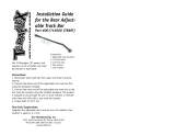
Using an appropriate jack, support the
knuckle.
Remove the single retaining rivet that se-
cures the inner fender liner.
Retain the clip for future installation.

www.ReadyLIFT.com - Phone: (877) 759-9991
7 62-21360-IM-AA
Remove the upper control arm heat shield
mounting bolt. The heat shield is located
on the rear pivot of the right (passenger)
side on the vehicle.
Retain the factory mounting hardware.
NOTE: NOT ALL VEHICLES ARE EQUIPPED WITH
THIS HEAT SHIELD.
When installing the driver side upper con-
trol arm you will need to disconnect the
steering linkage.
Remove the pinch bolt on the top u-joint.
NOTE: ENSURE THE STEERING WHEEL DOES
NOT ROTATE. STEERING SHAFT AND U-JOINT
NEED TO BE INSTALLED IN THE FACTORY ORI-
ENTATION OR ELSE THERE IS A HIGH POSSIBIL-
ITY TO DAMAGE THE CLOCK SPRING.
Remove the upper control arm ball joint
nut.
Dismard the factory nut.
Using a dead blow hammer or similar tool,
strike the knuckle on the side to dislodge
the ball joint taper.
Remove the upper control arm pivot bolt.
Retain the factory pivot bolts and
nuts.
Remove the upper control arm.

www.ReadyLIFT.com - Phone: (877) 759-9991
8 62-21360-IM-AA
Install the replacement upper control arms
using the factory mounting hardware.
Torque the factory nut to 120 ft-lbs.
Install upper ball joint to knuckle using
the supplied hardware.
Torque the M12 hardware to 55 ft-lbs.
Using the factory bolt install the upper
control arm heat shield on the passenger
side.
Torque the factory hardware to 80 in-lbs.
Install the pinch bolt on the top u-joint.
Torque the factory hardware to 55 ft-lbs.
NOTE: ENSURE THE STEERING WHEEL DID NOT
ROTATE. IT IS VERY INPORTANT THE STEERING
SHAFT AND U-JOINT ARE INSTALLED IN THE
FACTORY ORIENTATION OR ELSE THERE IS A
HIGH POSSIBILITY TO DAMAGE THE CLOCK
SPRING.
Loosen but do not remove the (3) top
strut nuts.

www.ReadyLIFT.com - Phone: (877) 759-9991
9 62-21360-IM-AA
Remove the lower strut nuts.
Discard the factory mounting hardware.
Loosen but do not remove the (2) forward
sway bar skid plate bolts.
Retain the factory mounting hardware.
Remove the sway bar end link from the
lower control arm.
Retain the factory mounting hardware.
NOTE: BE SURE TO REMOVE THE END LINK NUT
USING HAND TOOLS.
Remove both the driver and passenger
rear sway bar skid plate bolts.
Retain the factory mounting hardware.

www.ReadyLIFT.com - Phone: (877) 759-9991
10 62-21360-IM-AA
Remove both the driver and passenger for-
ward sway bar retainer cap bolts.
Retain the factory mounting hardware.
Remove both the driver and passenger
rear sway bar retainer cap nuts.
Retain the factory mounting hardware.
Lower the sway bar down and back to aid
in removal of the rear lower control arm
pivot bolt.
Remove the lower control arm pivots from
the frame side pivot pockets.
Retain the factory hardware.
NOTE: USE AN APPROPRIATE JAACK TO AID IN
THE REMOVAL OF THE PIVOT BOLTS.

www.ReadyLIFT.com - Phone: (877) 759-9991
11 62-21360-IM-AA
With the lower control arm pivot removed,
Swing the lower control arm down while
removing the lower strut studs from the
control arm.
Remove the (3) top strut nuts and carefully
remove the strut assembly from the vehi-
cle.
Retain the factory hardware.
CAUTION: BE SURE TO SUPPORT THE STRUT
WHILE REMOVING THE TOP STRUT NUTS.
Install the coilover top hat adaptor plate,
using the supplied thread locker and M10
flanged head bolts.
Torque the M10 bolts to 45 ft/lbs.
NOTE: BE SURE TO INSTALL THE TOP HAT
WITH THE LOGO FACES OUT, THIS WILL
ENSURE PROPER COILOVER INSTALLA-
TION ORIENTATION.
Install the correct coilover into the top hat.
NOTE: THE COILOVERS ARE ETCHED WITH A IN-
TENDED INSTALLATION LOCATION (FRONT,
LEFT / FRONT RIGHT)

www.ReadyLIFT.com - Phone: (877) 759-9991
12 62-21360-IM-AA
Install the provided M16 Flange bolt
through the top hat and coilover from
front to rear.
Install supplied M16 locking flange nut on-
to the coilover mounting bolt.
Torque the M16 hardware to 180 ft/lbs.
Raise the lower control arm up and guide
the lower strut into place. Install the ****
through the lower control and the coilover
bar pin.
Install the provide M14 locking flange
nuts.
Torque the M14 hardware to 120 ft/lbs.

www.ReadyLIFT.com - Phone: (877) 759-9991
13 62-21360-IM-AA
Using an appropriate jack, carefully jack
the lower control arm into the frame side
pivot pockets.
Install the factory cam bolts in the pivot
pockets in the factory orientation.
Install the factory alignment cam plate
over pivot bolt and then install nut.
Do not tighten at this time.
Install the sway bar end link into the low-
er control arm using the factory hardware.
Torque the factory nut to 55 ft-lbs.
NOTE: BE SURE TO INSTALL THE END
LINK NUT USING HAND TOOLS.
Raise the sway bar back into the factory
orientation.

www.ReadyLIFT.com - Phone: (877) 759-9991
14 62-21360-IM-AA
Install the driver and passenger rear sway
bar retainer cap nuts.
Do not tighten at this time.
Install the driver and passenger rear sway
bar retainer cap bolt.
Torque the factory nut to 55 ft-lbs.
Torque the factory bolt to 55 ft-lbs.
Install both the driver and passenger rear
sway bar skid plate bolts.
Torque the factory bolt to 35 ft-lbs.
Tighten the (2) forward sway bar skid
plate bolts.
Torque the factory bolt to 35 ft-lbs.

www.ReadyLIFT.com - Phone: (877) 759-9991
15 62-21360-IM-AA
Install the single retaining rivet that se-
cures the inner fender liner.
With everything tightened and torque to the specified specifications, install front tires
and lower vehicle.
With the steering wheel centered, turn the tie rod ends until the tires are straight. If
the steering wheel is not centered properly, the ABS/traction control lights may acti-
vate. Turn the wheels from lock to lock and make sure the brake lines and ABS rout-
ing clears all suspension components adequately. Reposition if necessary.

www.ReadyLIFT.com - Phone: (877) 759-9991
16 62-21360-IM-AA
Remove the rear wheels.
With the rear wheels removed, locate and
remove the (12) mounting clips and the
(3) mounting screws that hold the rear
fender liners in place.
Remove the rear fender liners.
Retain all the factory mounting hardware.
Rear Installation
Block the front tires and raise the rear of the vehicle using a suitable jack.
Support with jack stands at each frame rail in front of the rear lower control arm
hangers.

www.ReadyLIFT.com - Phone: (877) 759-9991
17 62-21360-IM-AA
To aid in the removal and installation pro-
cess, it is best to loosen the rear track bar
at the frame.
Do not remove the mounting hard-
ware.
Remove the track bar mounting hardware
from the axle mount
Retain the factory mounting hardware.
Install the supplied rear track bar bracket
in the factory location using the supplied
rear track bar bracket spacer and the fac-
tory track bar axle pivot bolt.
Do not tighten at this time.
Install the front track bar clamp on to the
axle.
Install the rear track bar clamp on to the
front side of the axle and aligned with the
front clamp.

www.ReadyLIFT.com - Phone: (877) 759-9991
18 62-21360-IM-AA
Align the (3) mounting hole on the track
bar bracket to the front track bar clamp.
Install the (3) M10-1.5 x 30mm hex flange
head bolts into the front track bar clamp
using thread locker.
Run bolts down to the bracket.
Do not tighten at this time.
Install the (6) M8-1.25 x 25mm socket cap
screws through the rear track bar clamp
and into the front track bar clamp.
Snug the M8 hardware too the clamp.
Do not tighten at this time.
Torque the M10 hardware to 60 ft./lbs.
Torque the M8 hardware to 35 ft./lbs.
Install the rear track bar into the track bar
bracket using the supplied M16 x 90mm
hex flange head bolt.
Do not tighten at this time.

www.ReadyLIFT.com - Phone: (877) 759-9991
19 62-21360-IM-AA
Torque the factory bolt to 120 ft-lbs.
Torque the rear track bar hardware to 150
ft-lbs.
Remove the factory track bar at this time.
Retain the factory mounting hardware.
Install the provided track bar using the
factory mounting hardware.
Do not tighten at this time.
NOTE: ENSURE TRACK BAR IS INSTALLED WITH
THE ADJUSTABLE SIDE TOWARDS THE AXLE.
Using an appropriate jack, support the
axle.
Remove the (3) top strut nuts and the
lower strut bolt. Lowering the axle will aid
in the removal of the rear strut. Remove
the rear strut assembly from the vehicle.
Retain the factory axle side mount-
ing hardware.

www.ReadyLIFT.com - Phone: (877) 759-9991
20 62-21360-IM-AA
RAISE THE REAR AXLE FOR THE SERIES
OF STEPS, THIS WILL ADD IN THE RE-
MOVAL AND INSTALLATION ON THE
REAR UPPER CONTROL ARM HARDWARE.
Remove the hardware shield located on
the right rear upper control arm axle
mount.
Using a 1/2” drill bit drill out the existing
hole used to mount the shield.
Be sure to paint exposed metal with quali-
ty rust preventative paint.
Remove the factory nut from the rear up-
per control arm pivot bolt.
Retain the factory mounting hardware.
Remove the factory bolt from the rear up-
per control arm mount.
Retain the factory mounting hardware.
/