Page is loading ...

www.ReadyLIFT.com - Phone: (877) 759-9991
49-23620-IM-AA
(877) 759-9991
MON-FRI 7AM-4PM PST
OR
EMAIL: support@readylift-ami.COM
WEBSITE: ReadyLIFT.COM
**Please retain this document in your vehicle at all times.**
IF your ReadyLIFT® product has a damaged or missing
part, please contact customer service directly and
a new replacement part will be sent to you immediately.
For warranty issues, please return to the place of
installation and contact ReadyLIFT.
Limited Lifetime Warranty
This unique product warranty proves our commitment to the quality and reliability of every product that
ReadyLIFT manufactures. The ReadyLIFT product warranty only extends to the original purchaser of any
ReadyLIFT product, if it breaks, we will give you a new part. Warranty does not apply to discontinued parts.
Our Limited Lifetime Warranty excludes the following ReadyLIFT items; bushings, bump stops, ball joints, tie
rod ends, heim joints and shock absorbers. These parts are subject to wear and are not considered defective
when worn. They are warranted for 12 months from the date of purchase for defects in workmanship.
This product warranty is voided if the vehicle is not aligned after kit installation and proper maintenance is
routinely done.
Product purchased directly from ReadyLIFT has a 90 day return policy on uninstalled products from the date
of purchase (may be subject to restocking fee). Uninstalled product returns must be in the original Ready-
LIFT packaging. Please call (877) 759-9991 to get an RGA# for any return. Customer is responsible for
shipping costs back to ReadyLIFT. Returns without RGA# will be refused. Contact ReadyLIFT directly
about any potentially defective parts prior to removal from vehicle.
ReadyLIFT products are NOT intended for off-road abuse. Any damage or failure as a result from off-road
abuse voids the warranty of the ReadyLIFT product. ReadyLIFT is NOT responsible for any subsequent dam-
ages to any related vehicle parts due to misuse, abuse, improper installation, or lack of maintenance. Fur-
thermore, ReadyLIFT reserves the right to change, modify or cancel this warranty without prior notice.
49-23620 2023-UP Super Duty 6” Lift w/ Radius Arm Drops

www.ReadyLIFT.com - Phone: (877) 759-9991
2 49-23620-IM-AA
READ INSTRUCTIONS THOROUGHLY AND COMPLETELY BEFORE BEGINNING INSTALLATION.
INSTALLATION BY A CERTIFIED PROFESSIONAL MECHANIC IS HIGHLY RECOMMENDED.
READYLIFT® IS NOT RESPONSIBLE FOR ANY DAMAGE OR FAILURE RESULTING FROM IMPROPER INSTALLATION.
Safety Warning
MISUSE OF THIS PRODUCT COULD LEAD TO INJURY OR DEATH.
Suspension systems or components that enhance the on and off-road performance of your vehicle may cause
it to handle differently than it did from the factory. Extreme care must be used to prevent loss of control or
vehicle rollover during abrupt maneuvers.
Always operate your vehicle at reduced speeds to ensure your ability to control your vehicle under all driving
conditions. Failure to drive safely may result in serious injury or death to driver and passengers.
Driver and passengers must ALWAYS wear your seat belts, avoid quick sharp turns and other sudden maneu-
vers. ReadyLIFT Suspension does not recommend the combined use of suspension lifts, body lifts, or other
lifting devices.
You should never operate your vehicle under the influence of alcohol or drugs.
Constant maintenance is required to keep your vehicle safe. Thoroughly inspect your vehicle before and after
every off-road use.
It is the responsibility of the retailer and/or the installer to review all state and local laws, with the end user
of this product, related to bumper height laws and the lifting of their vehicle before the purchase and installa-
tion of any ReadyLIFT products.
It is the responsibility of the driver/s to check their surrounding area for obstructions, people, and animals
before moving the vehicle.
All raised vehicles have increased blind spots; damage, injury and/or death can occur if these instructions are
not followed.
.
Installation Warning
All steps and procedures described in these instructions were performed while the vehicle was properly sup-
ported on a two post vehicle lift with safety jacks.
Use caution during all disassembly and assembly steps to insure suspension components are not over extend-
ed causing damage to any vehicle components and parts included in this kit.
Included instructions are guidelines only for recommended procedures and are not meant to be definitive.
Installer is responsible to insure a safe and controllable vehicle after performing modifications.
ReadyLIFT Suspension recommends the use of an OE Service Manual for model/year of vehicle when disas-
sembly and assembly of factory and related components.
Unless otherwise specified, tighten all bolts and fasteners to standard torque specifications listed within the
OE Service Manual.
Suspension components that use rubber or urethane bushings should be tightened with the vehicle at normal
ride height. This will prevent premature wear or failure of the bushing and maintain ride comfort.
Larger tire and wheel combinations may increase leverage on suspension, steering, and related components.
Due to payload options and initial ride height variances, the amount of lift is a base figure. Final ride height
dimensions may vary in accordance to original vehicle ride height. Always measure the vehicle ride height
prior to beginning installation.

www.ReadyLIFT.com - Phone: (877) 759-9991
3 49-23620-IM-AA
IMPORTANT NOTE:
This suspension system was developed using a 37” x 12.5” tire with 20” x 9” wheel
and a offset of +18mm. If wider tires are used, offset wheels may be necessary and
trimming may be required. Factory wheels can be used but are not recommended
with tires over 11.5” wide.
The stock spare rim can be run in an emergency - exercise extreme caution under
stock spare tire operating conditions. Please note that, if running the spare factory
tire, it is done for short distances and a speed not to exceed 45mph or damage to dif-
ferentials may occur.
A lifted vehicle may have different headlight aim performance. ReadyLIFT recom-
mends marking and recording the headlight beam position before kit installation and
then adjusting, if necessary, the headlamps to the same height settings after kit in-
stallation. Set the vehicle on a level surface 10' to 15’ from a solid wall or garage
door. (This is a general distance with some manufacturers requiring different distanc-
es.) Note the top height of the low beam's bright spot, the top of the most intense
part of the beam, for driver and passenger side. Height may vary from side to
side. Repeat this procedure and adjust after lift kit is installed. Adjust if the aim is off
by turning the adjusters gradually (a quarter of a turn) and looking to see where the
new alignment falls. It may be easier to block one headlamp while adjusting the oth-
er. Consult the owner operation manual for procedures to adjust headlights - many
automakers offer headlight aiming specs. Some states have their own specifications
when it comes to headlight aim, so it’s best to follow those rules when alighting head-
lights.
IMPORTANT NOTE:
The lift blocks in this kit are not designed to work with aftermarket or factory add on
air spring/load leveling kits that attach to the bump stop tangs. Use of this type of air
bag system will void all block warranties and can cause failure of the block bump stop
tang.

www.ReadyLIFT.com - Phone: (877) 759-9991
4 49-23620-IM-AA
VEHICLE RIDE HEIGHT MEASURMENTS
Measure from the fender edge to the axle hub center
Factory front axle Factory rear axle
ReadyLIFT target ReadyLIFT target
After Lifted After Lifted
Driver
Before
Driver
After
Passenger
Before
Passenger
After
RECORD HEAD LAMP MEASURMENTS
Pre Installation Measurements
It is imperative that you record the following measurements and factory components.
ReadyLIFT test and records as much data from each application as possible. Vehicle
manufactures may change components or add models with different options. By re-
cording and not exceeding the fender to hub center that ReadyLIFT call out will en-
sure the lift on your vehicle is correct. This measurements and components will effect
the completion of this lift kit. Failure to do so may result in over lifting, causing prem-
ature failure of axles, CV boots and drivetrain. Over lifting a vehicle will also result in
a incorrect wheel alignment. This will prematurely wear tires on the inside or outside
edges. Incorrect alignment will cause poor vehicle handling issues such as under
steer. Over lifting will also cause a shock top off condition, which may create poor
ride quality, damage the vehicle, introduce noises like clunks, and will prematurely
wear key components. Failure to adjust head lamps may cause dangerous driving
conditions for you and other drivers on the road. Record the head lamp position be-
fore the installation of this lift or leveling kit and adjusting to factory position after the
completion will ensure a safe and enjoyable experience.

www.ReadyLIFT.com - Phone: (877) 759-9991
5 49-23620-IM-AA
BILL OF MATERIALS
Before starting installation:
ReadyLIFT Suspension highly recommends that the installation of this
product be performed by a professional mechanic with experience working on and installing suspension
products. Professional knowledge and skill will typically yield the best installation results. If you need an
installer in your area, please contact ReadyLIFT Suspension Customer Service to find one of our “Pro-
Grade” Dealers.
INSTALLATION BY A PROFESSIONAL IS HIGHLY RECOMMENDED.
• A Factory Service Manual for your specific Year / Make / Model is highly recommended for reference
during installation.
• All lifted vehicles may require additional driveline modifications and / or balancing.
• A vehicle alignment is REQUIRED after installation of this product.
• Speedometer / Computer recalibration is required if changing +/- 10% from factory tire diameter.
• A vehicle lift or hoist greatly reduces installation time. Installation time estimates are based on an avail-
able vehicle hoist.
COMPONENTS
DESCRIPTION QTY
COIL SPRING FRONT PAIR 6" 1
DROP PITMAN ARM 1
CASTER BUSHING KIT 1
TRACK BAR BRACKET 1
TRACK BAR WASHER 2
FRONT BUMP STOP EXTENSION 2
FRONT SWAY BAR DROP, LEFT SIDE 1
FRONT SWAY BAR DROP, RIGHT SIDE 1
STEERING STABILIZER BRACKET (TIE ROD) 1
STEERING STABLIZER BRACKET (FRAME) 1
STEERING STABILIZER CONE WASHER 1
STEERING STABILIZER 1
BRAKE LINE BRACKET, LEFT 1
BRAKE LINE BRACKET, RIGHT 1
RADIUS ARM DROP CRUSH SLEEVE 2
RADIUS ARM DROP NUT PLT, LEFT 1
RADIUS ARM DROP NUT PLT, RIGHT 1
RADIUS ARM DROP BRACKET, LEFT 1
RADIUS ARM DROP BRACKET, RIGHT 1
REAR BLOCK, LEFT (DRIVER) 1
REAR BLOCK, RIGHT (PASSENGER) 1
U-BOLT 4
U-BOLT HARDWARE PACK 1
CARRIER DROP 1
FALCON FRONT SHOCKS 2
FALCON REAR SHOCKS 2
SHOCK SPACER 2
2023 FSD HUB VACUUM LINE, KIT 1
HARDWARE PACK 1
HARDWARE
DESCRIPTION QTY
Brake Line
M8-1.25 x 20mm HHB, Class 10.9, YZ 2
M8-1.25 C-Lock Nut, Class 10.9 2
M8 Flat Washer Class 10.9 4
Carrier Bearing
7/16"- 14 x 2.25" HHB (GR8) 2
7/16 Flat Washer (GR8) 2
Sway Bar Drop
M10-1.5 X 40mm HHB, Class 10.9, YZ 4
M10-1.5 C-Lock Nut, Class 10.9 4
M10 Flat Washer Class 10.9 8
Bump Stop
M8-1 C-Lock Nut(GR 10.9) 2
M8 Flat Washer (GR 8.8) 2
Steering Stabilizer
M12 - 1.75 x 70 mm HHB GR 10.9 2
M12 - 1.75 x 55 mm HHB GR 10.9 1
M12 - 1.75 x 35 mm HHB GR 10.9 3
M12 - 1.75 C-Lock Nut GR 10.9 3
M12 Flat Washer GR 10.9 6
Radius Arm Drop
M18(2.50) X 130 GR HHB 10.9 2
M18(2.50) X 40 HHB GR 10.9 2
M18(2.50) Lock Nut , CLASS 10 2
M18 Flat Washer 6
M18 Split Lock washer 2

www.ReadyLIFT.com - Phone: (877) 759-9991
6 49-23620-IM-AA
***Parts shown in red for picture clarification only***
ReadyLIFT recommends all steps and procedures described in these instructions be
performed while the vehicle is properly supported on a two post vehicle lift with safe-
ty jacks.
Otherwise, park vehicle on a clean flat surface and block the rear wheels for safety.
Engage the parking brake.
Disconnect the vehicle power source at the ground terminal on the battery.
Lock the steering wheel in the straight forward position with the column lock or steer-
ing wheel locking device.
Raise the front of the vehicle and support with safety jack stands at each frame rail
behind the lower control arms.
Remove front wheels/tires using care to prevent personal injury - wheel/tire assembly
is very heavy.
Remove the brake line bracket at the
frame.
Retain the factory hardware.
Remove the brake line bracket at the axle.
Retain the factory hardware.

www.ReadyLIFT.com - Phone: (877) 759-9991
7 49-23620-IM-AA
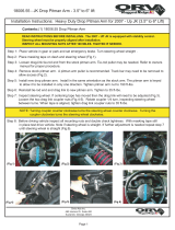
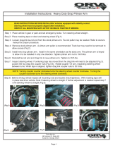
Remove the vacuum line clips from the
driver side radius arm.
Remove the axle vent line tube from the
top of the driver side shock and the inside
frame rail.
Remove the vacuum line clip from the
passenger side engine cross member.
Mark the drive shaft to pinion orientation,
then remove the drive shaft from the front
differential. Tape the u joint caps to keep
them from falling off / damage while
working.
Retain the factory hardware.

www.ReadyLIFT.com - Phone: (877) 759-9991
8 49-23620-IM-AA
Remove the transfer case skid plate.
Retain the factory hardware.
NOTE: THIS IS NOT A NECESSARY STEP BUT
MAY AID IN THE INSTALLATION PROCESS.
eave the axle hanging from the shocks.
Place a suitable jack under the tie rod
ends close to the knuckles.
Remove the radius arms at the frame. Re-
tain factory hardware.
Use the jack to rotate the axle up allowing
the radius arms to drop out of the frame
low enough to clear the ReadyLIFT radius
arm drops.
Insert the radius arm drop down brackets
into the mounting pocket.
Secure the radius arm drop down bracket
using the supplied 18mm X 130mm bolts,
sleeves and hardware.

www.ReadyLIFT.com - Phone: (877) 759-9991
9 49-23620-IM-AA
Slide the nutplate, into the frame. Using
the supplied 18mm X 40mm bolts, washer
and split washer, Install the bolt through
the radius arm drop bracket, rear cross-
member and nutplate.
Torque the M18 hardware to 250 ft-lb.
Carefully raise the radius arm into the
drop bracket and secure it using the pre-
viously removed OE hardware.
Do not tighten at this point.
Remove the jacks from under the tie rod
ends and place under the axle.
Remove the sway bar from the frame and
let hang.
Retain the factory hardware.
18mm x 40mm, split
washer, nut plate
OE hardware

www.ReadyLIFT.com - Phone: (877) 759-9991
10 49-23620-IM-AA
Remove the factory bump stop by grab-
bing and pulling it out of its mount using a
twisting/pulling motion.
Retain the factory bump stop.
Remove the bump stop mount from the
frame.
Discard the factory hardware.
Install the ReadyLIFT bump stop exten-
sion to the frame by threading it into the
existing bolt hole. Use a punch or similar
tool in the holes of the mount and tighten.
Install the bump stop mount to the exten-
sion using M8 nut and washer.
Mark a line across the edge of the outer
lip of the passenger side bump stop
mount parallel to the frame.
Remove the passenger side bump stop
mount and use a suitable cutting device,
trim off the marked edge. This is for
spring clearance under suspension full
droop and articulation. Paint the exposed
metal with a quality rust preventative
paint.

www.ReadyLIFT.com - Phone: (877) 759-9991
11 49-23620-IM-AA
Using the supplied M8 locking nut and
washer, Install bump stop mount to the
ReadyLIFT extension making sure the cut
edge faces to the inside of the vehicle.
Torque the nut to 5 ft-lbs.
Install the factory bump stop into the cup
in a factory orientation.
Remove the track bar at the track bar
bracket. Let hang out of the way.
Retain the factory hardware.
Remove the steering stabilizer from the
frame.
Discard the factory hardware.

www.ReadyLIFT.com - Phone: (877) 759-9991
12 49-23620-IM-AA
Remove the steering stabilizer nut from
the tie rod. Use an air hammer or other
suitable device to dislodge the taper.
Remove the tie rod end at the pitman
arm. Strike the pitman arm with a dead
blow hammer to dislodge the taper.
Retain the factory hardware.
Remove the factory track bar bracket by
removing the 2 vertical bolts and 3 hori-
zontal nuts.
Retain the factory hardware.
Remove the pitman arm nut. Using a pit-
man arm puller, remove the pitman arm
from the steering gear box.

www.ReadyLIFT.com - Phone: (877) 759-9991
13 49-23620-IM-AA
Clean off any debris off the sector shaft.
Coat the sector shaft splines with a light
duty liquid based lubricant or oil.
Install the drop pitman arm using the fac-
tory nut. Remove the nut, and clean off
any lubricant from the sector shaft and
pitman arm nut threads and apply a liberal
amount of thread locker. Run tight. Use a
chain or other suitable strap through the
pitman arm tie rod mounting hole to the
passenger side frame rail to keep gear box
from turning.
Torque the pitman arm nut to 450 ft-lbs.
Remove the shock from the axle.
Retain the factory hardware.
Lower the axle enough to remove the
front springs. Remove the shock from the
frame.
Discard the factory shocks and
springs.

www.ReadyLIFT.com - Phone: (877) 759-9991
14 49-23620-IM-AA
Install the ReadyLIFT track bar mount to
the frame using factory hardware.
Torque the factory hardware to 120 ft-lbs.
Install the track bar into the ReadyLIFT
track bar mount using the factory hard-
ware and the ReadyLIFT offset square
washers. Make sure the offset is closest to
the driver side, as shown.
Loosen the tie rod adjuster and flip the tie
rod 180 degrees and install to the Ready-
LIFT pitman arm using factory hardware.
Torque the nut to 70 ft-lbs.
Install the safety keeper and cotter pin.
Install the factory isolator onto the provid-
ed lift springs, and then the springs onto
the axle making sure to clock the dead
end of the spring into the spring lock.
Raise the axle enough to hold the springs
into place.

www.ReadyLIFT.com - Phone: (877) 759-9991
15 49-23620-IM-AA
Install the Falcon Front Shock using the
provided hardware on the top.
Torque the upper shock hardware to 35 ft
-lbs.
Using the factory hardware on the bot-
tom, install into the lower shock perch.
Do not torque at this time.
Install the ReadyLIFT steering stabilizer
bracket to the frame using M12 x 35mm
bolt and washer. Do not tighten until the
stabilizer has been test fit so as to estab-
lish the brackets final orientation.
Install the ReadyLIFT steering stabilizer
bracket to the tie rod using M12 x 55mm
bolt, washers, cone adapter, and nut.
Cone adapter will install from the bottom
going up. Do not tighten at this time. The
stabilizer must be test fit to establish the
bracket's final orientation.

www.ReadyLIFT.com - Phone: (877) 759-9991
16 49-23620-IM-AA
Install the steering stabilizer to the brack-
ets using M12 x 70mm bolts, washers,
and nuts. Mark the orientation of the
brackets to the tie rod end and frame
mount. Remove the stabilizer.
Torque the mount hardware to 45 ft-lbs.
Reinstall the steering stabilizer and torque
hardware to 45 ft-lbs.
Remove the barb connector from vacuum
line elbow.
Install the fir tree cable tie into the radius.
Install the supplied barbed coupler and
vacuum line in between the factory line
and the elbow.

www.ReadyLIFT.com - Phone: (877) 759-9991
17 49-23620-IM-AA
Zip tie the driver side vacuum line to the
vent tube making sure that it can not be
pinched by the bump stop when the sus-
pension cycles.
Install the brake line extensions into the
factory bracket location using the factory
bolt.
Torque the bolt to 5 ft-lbs.
Do not over tighten and strip the
threads.
Gently pull down on the metal line until
you can get the bracket to line up with the
bottom two holes on the brake line drop.
Ensure to not kink the metal line.
Install the factory brackets using M8 x
20mm bolts, washers, and nuts. Install
bolts facing inward.
Torque the M8 hardware to 10 ft-lbs.
Install the sway bar drop brackets onto
the frame using factory hardware.
Torque the factory nuts to 45 ft-lbs.

www.ReadyLIFT.com - Phone: (877) 759-9991
18 49-23620-IM-AA
Install sway bar to brackets using provid-
ed M10 x 40mm bolt, washer and locking
nut.
Torque the M10 hardware to 45 ft-lbs.
Install the front wheels. Lower the vehicle to the ground. Torque the lug nuts to the
wheel manufacturers specs. Jounce the vehicle a few times to settle it to the new ride
height. Install the front drive shaft using the factory hardware with a drop of thread
locker. Torque to 26 ft-lbs, the lower shock hardware to 65 ft-lbs, the radius arm
hardware to 200 ft-lbs, track bar at the bracket to 350 ft-lbs.
Block the front tires and raise the rear of the vehicle using a suitable jack. Support
with jack stands at each frame rail in front of the rear leaf spring hangers.

www.ReadyLIFT.com - Phone: (877) 759-9991
19 49-23620-IM-AA
Support the axle with a suitable jack. Re-
move the rear shocks from the axle and
frame. Retain factory hardware.
Loosen but do not remove the passenger
side u-bolts. Remove the driver side u-
bolts completely and lower the axle.
Install the ReadyLIFT driver side block (D
is cut into the block under the bump stop
tang) and raise the axle lining the center
pins up. Install using the provided u-bolts
and nuts but do not fully tighten at this
time. Repeat steps for the passenger side.
(P is cut into the block under the bump
stop tang)
Install aftermarket rear shock using facto-
ry hardware. Do not tighten at this time.

www.ReadyLIFT.com - Phone: (877) 759-9991
20 49-23620-IM-AA
If equipped with a 2 piece driveline, re-
move the bolts holding the carrier bearing
to the frame. Install the ReadyLIFT carrier
bearing spacer between the carrier bear-
ing and frame using 7/16” bolts, washers
and a drop of thread locker. Torque to 50
ft-lbs.
Install the wheels and lower the vehicle to the ground.
Torque the lug nuts to the wheel manufacturers specs. Jounce the vehicle to settle it
to the new ride height. Torque the shock hardware to 65 ft-lbs, and the u-bolts to 110
ft-lbs.
Reconnect the vehicle power source at the ground terminal on both batteries. Adjust
steering wheel center and toe before driving or you could have dash warning lights
come on.
/