Page is loading ...

The Toro Company – 2001
Printed in USA
All Rights Reserved
FORM NO. 3326–279
INSTALLATION
INSTRUCTIONS
Part No. 105–1665
Single–Belt PTO Kit
Z–Master 300 Series
Loose Parts
Note: Use the chart below to identify parts for assembly.
DESCRIPTION QTY. USE
Rotor
Pulley and armature
1
1
Install clutch parts
Belt 1 Install clutch and belt
Remove Bumper
1. Remove bumper from the machine (Fig. 1).
m-5445
1
Figure 1
1. Bumper
Remove Clutch
1. Remove tensioner spring on idler (Fig. 2).
2. Disconnect the wire lead from clutch.
3. Remove PTO belts from clutch pulley (Fig. 2).
4. Remove bolt from clutch and remove clutch.
1 m–5437
2
3
4
45
Figure 2
1. Tensioner spring
2. Idler
3. PTO belts
4. Clutch pulley
5. Bolt
6. Clutch
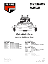
Install Clutch Parts
1. Remove the pulley and armature assembly from
the clutch assembly (Fig. 3).

Installation Instructions
2
2. Drive the rotor post out from the clutch
assembly. Remove the rotor from assembly.
Note: Make sure the rotor is replaced with
the new one provided.
m–5446
3
4
1
2
5
6
Figure 3
1. Pulley and armature
assembly
2. Clutch assembly
3. Rotor post
4. Rotor
5. Clutch magnets
6. Wire lead
3. Install new rotor into assembly and onto the
rotor post (Fig. 3).
4. Install new armature and pulley onto the rotor
and under the clutch magnets (Fig. 3).
Install Clutch and Belt
1. Install new single belt onto gearbox pulley
before clutch is installed.
2. Slide clutch onto the drive shaft (Fig. 2).
Note: Make sure clutch is connected to
holding bar in the 6 and 9 o’clock
position (Fig. 4).
3. Install belt onto clutch pulley (Fig. 4).
Note: Check to make sure the belt is aligned
with gear box and clutch pulley. Align
the gear box if needed.
4. Install bolt into clutch (Fig. 2). Torque to
50ft.–lbs.
1
m–5438
4
6
2
5
3
Figure 4
1. Holding bar
2. 6 and 9 o’clock position
3. Belt
4. Clutch
5. Gearbox pulley
6. Bolt
5. Attach tensioner spring (Fig. 2).
6. Connect the wire lead from clutch (Fig. 3).
7. Install bumper (Fig. 1).
/