
INSTALLATION INSTRUCTIONS
For Model 1974-1
READ AND SAVE THESE INSTRUCTIONS
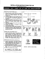
WAR N IN G ! SH UT POWER OF F AT FU SE OR CIRCU IT BRE AK ER .
AVERTISSEMENT! COUPER LE COURANT AU NIVEAU DES FUSIBLES OU DU DISJONCTEUR.
Fig.1
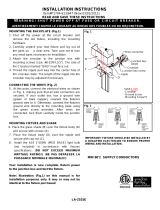
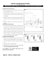
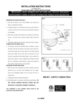
MOUNTING THE BACKPLATE (Fig.1)
1. Shut off the power at the circuit breaker and remove old fixture,
including the crossbar.
2. Carefully unpack your new fixture and lay out all the parts on a clear
area. Take care not to lose any small parts necessary for installation.
3. Attach the crossbar (A) to the outlet box using two outlet Box Screws
(B). The side of the Crossbar marked “GND” must face out.
4. Thread the nipple(C) part way into the center hole of the crossbar(A).
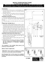
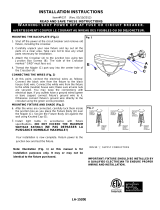
CONNECTING THE WIRES (Fig. 2)
1. At the point, connect the electrical wires as follow, Connect the black
wire from the fixture to the black house (hot) wire. Connect the white
wire from the fixture to the white (neutral) house wire. Make sure all
wire nuts are secured. You may wrap the connections with electrical
tape. If your outlet box has a ground wire (green or bare copper)
connects fixture’s ground wire to it. Otherwise connect fixture’s
ground wire directly to the crossbar using the green screw provided.
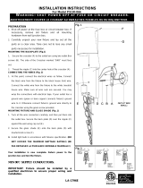
MOUNTING FIXTURE AND SHADE
1. After the wires are connected tuck them carefully inside the outlet box
as you place the backplate (E) over the nipple (C). Secure the
backplate (E) against the wall using Cap Nut (D).
2. Install glass shade by referring to fig.1.
3. Install the bulb in accordance with the fixture’s specification. (DO NOT
EXCEED THE MAXIMUM WATTAGE RATING!!) (NE PAS
DEPASSER LA PUISSANCE NOMINALE MAXIMALE!).
(NE
Your installation is now complete. Return power to the junction box
and test the fixture.
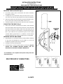
MIN 75℃ SUPPLY CONDUCTORS
D
LA-1847E
-
 1
1

Ask a question and I''ll find the answer in the document
Finding information in a document is now easier with AI
Related papers
-
 George Kovacs P1704-613 User manual
-
The Great Outdoors 9836 User manual
-
 George Kovacs P5131-066 User manual
-
 George Kovacs P5130-066 User manual
-
Minka Group 841-91 User manual
-
-
-
-
-


Other documents
-
 Minka Lavery 971-138 Installation guide
-
 Minka Lavery 1972-138 Installation guide
-
 Minka Lavery 976-1-138 Installation guide
-
 George Kovacs P5710-084 User manual
-
 Minka Lavery 1974-1-138 Installation guide
-
 Minka Lavery 1971-138 Installation guide
-
Kenroy Home 90903BRZ User manual
-
 Minka Lavery 345-37B Installation guide
-
-
 George Kovacs P037-077 User manual


