Page is loading ...

March 2018
Ver.1
BAT TERY POWERED WHEELBARROW
XUC01
REPAIR MANUAL

2 / 41
1 CONTENTS
1
CONTENTS ................................................................................................................................................................................. 2
2 CAUTION .................................................................................................................................................................................... 3
3 NECESSARY REPAIRING TOOLS ........................................................................................................................................... 3
4 FASTENING TORQUE ............................................................................................................................................................... 4
5 LUBRICANT AND ADHESIVE APPLICATION ...................................................................................................................... 4
6 REPAIR ........................................................................................................................................................................................ 5
6-1 Battery .................................................................................................................................................................................. 5
6-1-1 Disassembling ............................................................................................................................................................. 5
6-2 Frame ................................................................................................................................................................................... 5
6-2-1 Disassembling ............................................................................................................................................................. 5
6-3 Battery box ........................................................................................................................................................................... 6
6-3-1 Disassembling (Repair can be done with Upper frame) .............................................................................................. 6
6-3-2 Assembling .................................................................................................................................................................. 7
6-4 Switch box ........................................................................................................................................................................... 8
6-4-1 Disassembling ............................................................................................................................................................. 8
6-4-2 Assembling .................................................................................................................................................................. 9
6-5 LED light ........................................................................................................................................................................... 10
6-5-1 Disassembling ........................................................................................................................................................... 10
6-5-2 Assembling ................................................................................................................................................................ 11
6-6 Brake .................................................................................................................................................................................. 12
6-6-1 Disassembling ........................................................................................................................................................... 12
6-6-2 Assembling ................................................................................................................................................................ 13
6-7 Front tire, Wheel (Motor) ................................................................................................................................................... 14
6-7-1 Disassembling ........................................................................................................................................................... 14
6-7-2 Assembling ................................................................................................................................................................ 17
6-8 Puncture repair of Front tire 430 ........................................................................................................................................ 20
7 CIRCUIT DIAGRAM ................................................................................................................................................................ 21
8 WIRING DIAGRAM ................................................................................................................................................................. 23
8-1 Center case section ............................................................................................................................................................. 23
8-1-1 Assembling of Controller .......................................................................................................................................... 23
8-1-2 Assembling of Terminal ............................................................................................................................................ 23
8-1-3 Assembling of other than Power supply cord ............................................................................................................ 24
8-1-4 Assembling of Power supply cord ............................................................................................................................. 28
8-1-5 Assembling of Battery changeover switch ................................................................................................................ 31
8-2 Switch box section ............................................................................................................................................................. 32
8-3 LED Light case section ...................................................................................................................................................... 33
8-4 Fixing of Band ................................................................................................................................................................... 34
8-5 Wiring ................................................................................................................................................................................ 35
8-5-1 Position 1 ................................................................................................................................................................... 35
8-5-2 Position 2 ................................................................................................................................................................... 36
8-5-3 Position 3 ................................................................................................................................................................... 37
8-5-4 Position 4 ................................................................................................................................................................... 38
8-5-5 Position 5 ................................................................................................................................................................... 39
8-5-6 Position 6 ................................................................................................................................................................... 40
8-5-7 Position 7 ................................................................................................................................................................... 41

3 / 41
2 CAUTION
Repair the machine in accordance with “Instruction manual” or “Safety instructions”.
Follow the instructions described below in advance before repairing:
・ Wear gloves.
・ In order to avoid wrong reassembly, draw or write down where and how the parts are assembled, and what the parts are.
It is also recommended to have boxes ready to keep disassembled parts by group.
・ Handle the disassembled parts carefully. Clean and wash them properly.
3 NECESSARY REPAIRING TOOLS
Code No.
Description
Use for
1R015-A
Hex head bit H4-150 tightening/ loosening Hex. socket head bolts
1R263
Bearing extractor
replacing Snap in valve
1R366
Feeler gauge set
adjusting the gap between Brake disc and Brake caliper
1R411
Lead wire insert
fixing lead wires in lead wire holders
commercial
product
Bead cream
replacing Front tire 430
commercial
product
Lever for replacing tires (2 pcs) replacing Front tire 430
commercial
product
Tire chucking
Supporting tool for air injection into Front tire 430
commercial
product
Tire pressure gauge checking air pressure of Front tire 430
commercial
product
Valve clip Replacing Valve core (valve rubber) inside of Snap in
valve (commercial product)
commercial
product
Decorative valve cap installing Snap in valve
P/N:941201-0
Flat washer 8 installing Snap in valve

4 / 41
4 FASTENING TORQUE
Parts to fasten Fastener
Tightening torque
(N
・
m)
Cover (LED light)
Frame
M5x16 Hex socket head bolt
3.5 – 4.5
Wheel
Frame
M16x1.5 Hex nut
40 – 50
5 LUBRICANT AND ADHESIVE APPLICATION
Apply the following lubricants and adhesives.
Lubricant
Amount
Makita grease FA. No.2
a little
Bead cream (commercial product)
a little
Fig. 1
Outer periphery of Snap in Valve
Outer periphery of Sleeve 17
Inner periphery of Light case cover
Bead portion of Front tire 430

5 / 41
6 REPAIR
6-1 Battery
6-1-1 Disassembling
1 Remove Battery from the machine before repair.
6-2 Frame
6-2-1 Disassembling
Fig. 1
1
Release Rock lever [1].
2
Loosen M8x25 Thumb screw [3] (4pcs) and remove Spring
washer 8 [4], Flat washer 8 [5], M8x50 Hex bolt [6],
M8x75 Hex bolt [7] (2pcs) and then remove Frame [2].
Fig. 2
3
Upper frame [3] can be disassembled from Lower frame [5]
as follows.
4
Attach a Monkey wrench [8] to M16 x 24 Hex nut [7] to
lock and then remove M16 x 50 Hex bolt [1] with a socket
[9] and Impact Driver. (left/right both sides)
5
The components are as follows.
・ Flat washer 17 [2] (2pcs)
・ Sleeve 17 [4] (Apply lubricant to when assembling)
・ Spring washer 16 [6]
[1]
[2]
[7]
[6]
[3]
[4]
[5]
[1]
[4]
[3]
[5]
[2]
[6]
[8]
[9]
[3]
[5]
[3]
[5]
[7]

6 / 41
6-3 Battery box
6-3-1 Disassembling (Repair can be done with Upper frame)
Fig. 3
1
Remove four M5x14 H.S.H.Bolt WR [1] with 1R015-A
and Impact driver and take out Battery box assembly
[2].
Tips
Prepare a workbench [3] to put Battery box assembly [2].
Fig. 4
2
Remove Binding PT3x16 Tapping screws (8 pcs) [1]
and remove Front cover [2].
Fig. 5
3
Repair Controllers and other electric parts according to
Circuit diagram and Wiring diagram.
4
Remove Binding PT 3x16 Tapping [1] (5 pcs) and
remove Battery box [2].
5
Leaf springs [3] (2 pcs) are removed from Battery box
[2].
Note
Be careful not to lose Leaf spring [3] (2pcs).
Fig. 6
6
Remove PT 3x16 Tapping screws [1] (2 pcs) from
Terminal side and remove Terminal holder [2].
7
Remove Terminals[4] from Center case [3] (2 pcs).
[1]
[2]
[3]
[1]
[2]
1R015-A
[3]
[2]
[2]
[1]
[3]
[2]
[1]
[4]

7 / 41
6-3-2 Assembling
Fig. 7
1
Insert claw portion of Terminal [2] into the groove of
Ceter case [1].
2
Put Terminal holder[4] onto Center case [1] so as not to
pinch Lead wires and then fasten them with PT
3x16Tapping screws [3] (2 pcs).
Fig. 8
3
Insert Leaf springs [1] (2 pcs) to Battery box and
assemble it to Center case[3].
4
Assemble Battery box[2] fastening with Tapping screws
bind PT 3x16 [4] (5 pcs).
5
Assemble electric parts according to Circuit diagram 7
and Wiring diagram 8.
6
Assemble by the reversing procedure. Fasten Front cover and assemble it to Sub frame.
[2]
[1]
[3]
[4]
[1]
[2]
[3]
[4]

8 / 41
6-4 Switch box
6-4-1 Disassembling
Fig. 9
1
Remove M8x20 Hex bolt [1] and M8x40 Collar bolt [2].
Then pull off Handle R [4] from Sub frame [3].
Tips
Prepare a workbench or a box to put Handle R [4].
Fig. 10
2
Remove Binding PT 3x16 Tapping screw [1] (5 pcs) and
open Switch box L [2]. Electric parts can be removed
without disassembling Switch box R [3].
Fig. 11
3
Remove Switch [1] pushing lock of receptacle [2] with a
slotted screwdriver. This Receptacle is with lock.
[1]
[2]
[3]
[3]
[4]
[2]
[1]
[1]
[2]
Slotted
screwdriver

9 / 41
6-4-2 Assembling
Fig. 12
1
Assemble Switch lever [1] and Torsion spring 11 [2] as
shown in the left Fig.
Fig. 13
2
Assemble Switch plate [1] by connecting Connector to
Switch box through the bottom of pipe of Handle R.
Fig. 14
3
Assemble Pipe clamp 28 [1] if they are disassembled.
Pipe clamp is non-directional in spite of the different shape
of the ends of Pipe clamp.
Fig. 15
4
Insert a Hex wrench 4 into yellow arrow ( ) of Switch
box[1] and fit Switch box to Handle R by loosening/
tightening M5x16 S.H. Bolts (2 pcs).
How to adjust: 1.Distance from Grip [2] end: 0 -
3mm
2.Switch box must be fixed right angle
against the ground.
[1]
[1]
[2]
[1]
[2]
[1]
[2]
0 - 3mm

10 / 41
6-5 LED light
6-5-1 Disassembling
Fig. 16
1
(In case of replacing only LED lights)
Remove only inside Bind PT 3x16 Tapping screws [2] (2
pcs). Then LED light assembly [1] can be disassembled.
Fig. 17
2
Remove CT 4x16 Tapping screws [1] (4pcs) and remove
Light case cover [2] (Left/ right both Lights)
3
Remove Cover [3] turning left by hand and then remove
Lenz [5], Reflector [6], O ring 53 [7]. If you remove Cover,
O ring [4] is removed together.
Tips
Put some board on the center Lower frame to make a
workbench.
Fig. 18
4
Remove CT 4x16 Tapping screws [1] (4pcs) and remove
Strain relief [2], and pull off Connector [3] to dismantle
LED circuit.
*The left Fig. is right side LED light.
Fig. 19
5
If you repair Guard R/L [1], remove M5x16 H.S.H. bolt [2]
(2 pcs). (Outside two bolts among total four bolts.)
[2]
[2]
[1]
[1]
[2]
[3]
[4]
[5]
[6]
[7]
[2]
[1]
[2]
[3]
[4]
[2]
[1]
[2]

11 / 41
*
Fig. 20
6
Loosening engagement of Clamp A [1] and Clamp B [2]
remove LED light assembly [4]section from Lower frame
[3].
6-5-2 Assembling
Fig. 21
1
Assemble Reflector [1] by engaging four protrusions with
four holes on LED circuit [1]. Though bottom shape of
Reflector is rectangular, it is non-directional.
Fig. 22
2
Insert the protrusion of Clamp A [1] into the hole of Lower
frame. In this way LED light assembly position is fixed.
[1]
[2]
[3]
[4]
[1]
[2]
[1]
[2]

12 / 41
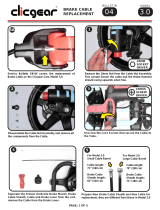
6-6 Brake
6-6-1 Disassembling
Fig. 23
1
Loosening M6x18 H.S.H bolt W/WR [1] (2 pcs) of Brake
caliper assembly, pull off Brake cable through Adjust screw
section [2].
Fig. 24
2
Removing M6x18 H.S.H bolt W/WR [1] (2 pcs) remove
Brake caliper assembly [3] from Lower frame [2].
Fig. 25
3
Remove two screws [1] and Connector [2] and then
disassemble Brake pad [3] and Pad spring [4] (2 pcs).
The components of Brake caliper assembly are as shown
left.
[1]
[3]
[2]
[1]
[2]
[3]
[4]
[1]
[3]
[2]

13 / 41
Fig. 26
4
Pull off Brake cable [3] by adjusting slit of Adjust screw of
Brake assembly [1].
5
Pulling up Brake lever [4], remove nipple of Brake cable
[3] from Brake lever [4].
Fig. 27
6
Remove Hex socket bolts (2 pcs) [1] and Brake assembly
[3] from Handle complete.
6-6-2 Assembling
Fig. 28
1
Assemble by reversing the disassembly procedure.
Assemble Brake assembly and Brake cable. Adjust Brake
lever so that it is placed vertical direction to the ground as
shown left Fig.
Tips
Fasten the Adjust screw at Brake assembly and Brake caliper
assembly with Brake cable so tight that cable length can be
adjusted long enough even if it is extended.
Fig. 29
2
While engaging both Pad spring [4] and Pad hole [5] fasten
Brake caliper and Connector [3] with Screws.
[1]
[2]
[3]
[1]
[2]
[3]
[3]
[4]
[1]
[2]
[3]
[4]
[5]

14 / 41
Fig. 30
3
Temporary fasten Brake caliper with M6x18 H.S.H bolts
W/ WR [1].
4
Inserting 1R366 (0.1mm) between Brake disc [2] and
Brake pad [3] support Lever [3] to apply Brake effectively.
Eliminating the sagging of Brake cable, fasten Hex socket
bolts [1] (2 pcs) and then a Hex socket bolt [5] to fix Brake
cable.
5
After adjusting the Brake switch on the motor to check the following parts for proper function.
・When you pull a Brake lever, brake works effectively before you pull half of the Lever.
・When you don’t pull a Brake lever, the Wheelbarrow moves ahead with/ without battery power, without generating
noise nor resistance etc.
・When you pull a Brake lever while Switch lever is being pulled, Motor stops.
6-7 Front tire, Wheel (Motor)
6-7-1 Disassembling
*If you repair Front tire assembly you can start from Fig.35 (next page).
1
Remove Brake caliper according to 6-6 (P12) to prevent from interference of Brake disc and Brake shoe at
assembling procedure.
2
Open Front cover according to 6-3 (P6) and then remove Strain relief connected to Motor and Connector. Then
cut three Closed end splices.
Fig. 31
3
Remove Cord by cutting Band[1] with a nipper. Inside part
of Band falls into Frame when it is cut off. But it is no
problem.
Note
Band [1] should be replaced every time when the machine is
repaired.
Fig. 31
4
Turn the machine upside-down and put Lower frame [1] on
a support stand or conntainer box. Then Front tire is seen
just before your eyes.
5
Remove M16-24 Hex nuts (2 pcs, left/right of Wheel[3] )
[4], and Flat washer 17 [5] (2 pcs) with an Impact driver
attached Socket 24 [2].
[2]
1R36
[3]
[4]
[5]
[1]
[2]
[3]
[4]
[5]
[1]
[1]
[2]
[1]
[2]

15 / 41
Fig. 33
6
Remove Front tire 430 [1] by lifting it up from Lower
frame [2].
Note
Two Washer [3] are attached at both left and right side of axle.
Two Coned disc spring 16 [4] are attached at opposite side of
Brake.
Fig. 34
7
Remove six Hex socket head Button bolt [1] and remove
Brake disc [2].
Note
Six Flat washers are attached opposite side of Brake disc.
Be careful not to lose them.
Fig. 32
8
Insert Valve clip [2] into Snap in Valve [1] and then turn
Valve core [3] counter clockwise to extract the air of Tire.
Note
Valve core (Valve rubber) can be supplied at local market.
Otherwise replace Snap in valve because it includes Valve
core. Be careful not to lose Valve core .
Fig. 36
9
Press down the center side of Tire 430 [1] with Arbor press
and remove one part of Wheel from the rim[3] of Front tire
430 [1].
[1]
[2]
[3]
[2]
[3]
[1]
[4]
[2]
[1]
[3]
[1]
[3]
[2]

16 / 41
Fig. 37
10
Remove Wheel [3] with a Lever for replacing tire [1] from
Front tire 430 [2].
Fig. 38
11
Pull off Snap in valve [1] from Wheel [2] by pushing it
with Arbor press and 1R283 etc.
[1]
[2]
1R283
[1]
[3]
[2]

17 / 41
Fig. 39
12
Grasp Snap in valve [1] with a plier and pull off from
Wheel [2].
6-7-2 Assembling
Fig. 33
1
Apply Bead cream [3] to insert surface of Snap in valve [1]
and a mounting hole [2] of Wheel all around.
2
Insert Snap in valve [1] into the hole [2] of Wheel by
picking up screw side of Valve [1] to pass through the hole.
3
Put Flat washer 8 [5] onto screw side of Snap in valve [1]
and then fasten Decorative valve cap [6] (commercial
product) by lifting up the Flat washer 8 with 1R263.
Tips
Don’t fasten Decorative valve cap [6] so tightly because
if it is fastened tightly 1R263 cannot be hooked under the
Washer.
Fig. 41
4
Apply Bead cream around the edge of the beads of Front
tire 430 [1] as shown in red dot of left Fig. Also apply Bead
cream to the Wheel-inserting side.
5
Also apply Bead cream around the periphery of bead seat
of the Wheel[2].
Tips
Apply Bead cream rather a lot to prevent from air leak
and lubrication for engagement.
[1]
[2]
[1]
[3]
[2]
1R263
[4]
[6]
[5]
Lid of Bead cream
Bead cream
[1]
[2]

18 / 41
Fig. 42
6
Insert the Yellow line side of Front tire 430 [1] into Brake
disc side of Wheel and engage lower side of Beads with a
Lever [2] for replacing tire.
Tips
Be careful not to make a damage to Wiring of Motor [3]
and Snap in valve [4] and assemble Front tire 430 [1].
If the opposite side of Snap in valve is inserted first it can
be smoothly assembled.
Fig. 43
7
Apply Bead cream to the opposite side of Bead.
Fig. 44
8
Engage the Wheel and Front Tire with Lever for replacing a
tire. Snap in valve [2] area must be inserted in the final step
of insertion.
Fig. 45
9
Put upside-down the Wheel [1]. Turning it push Front tire
430 [2] and pull the Wheel [1] to engage opposite (wiring)
side of Wheel and the Tire.
Tips
If the engagement is smoothly done the sound “poo” will
be heard .
10
Remove Valve core according to Fig.35.
Tips
If Valve core is removed, air will be smoothly pumped up
and bead of Wheel and Tire can be smoothly engaged.
[1]
[2]
[1]
[2]
[1]
[2]
[3]
[4]
Yellow line

19 / 41
Fig. 46
11
Prepare some wood stand to put Wheel.( only Wheel to turn
Front tire) Put the wiring side of Wheel upward.
12
Engage bead of Front tire 430 and Wheel by pushing down
the tire. And then pump up to be engaged completely.
Fig. 347
13
Insert Valve core with Valve clip [1] to prevent from air
leakage out of Front tire.
Note
Adjust air pressure to designated 0.23Mpa with Air gauge
[2] .
Fig. 48
14
Check air leakage by applying soap water to beads area [1]
of the tire and Snap in valve [2].
Note
Don’t put Wheel engaged with the Tire into water to avoid
immersion of Motor.
Tips
If there is an air leakage, bubble comes out. Or film forms
and then it breaks.
Fig. 49
15
Tighten Cap [2] with Snap in valve [1] by hand.
Fig. 50
16
Assemble by reversing 6-7-1 Disassembling procedure.
Note
・Assemble Brake disc [2] with the face without printing
・
Insert six Flat washers between Brake disc [2] and
Wheel and then tighten them with Hex socket head
bolts (6 pcs).
[2]
[1]
[3]
[1]
[2]
[1]
[2]
[1]
[2]
Wood stand

20 / 41
Fig. 35
17
When Band to connect each wiring is cut with a nipper all
Bands must be replaced with a new one. After fastened with
a new one extra Band must be cut down.
6-8 Puncture repair of Front tire 430
1
Puncture repair of Front tire is to be consigned to outside Repair agency such as Auto-repair shops. In that case
designated air pressure 0.23Mpa must be noticed to them.
/