Zap DX User manual

Type
User manual
Patent #5,491,390 #5,671,821 Other Patents Pending
ZAPWORLD.COM
where transportation is going
One ZAP Drive •117 Morris Street • Sebastopol California 95472 U.S.A.
tel (707) 824-4150 • fax (707) 824-4159
e-mail: [email protected] • Stock Symbol:ZAPP
©2001 ZAPWORLD.COM. All Rights Reserved. ZAP
®
is a registered trademark.
OWNER’S MANUAL
DX
ZAP POWER SYSTEM
MADE IN THE USA
$2.00
REV 5/15/00
YOUR INSURANCE POLICIES
MAY NOT PROVIDE COVERAGE
FOR ACCIDENTS INVOLVING
THE USE OF THIS BICYCLE.
TO DETERMINE IF COVERAGE
IS PROVIDED, YOU SHOULD
CONTACT YOUR INSURANCE
COMPANY OR AGENT.
STOP
STOP
BEFORE
YOU ZAP
YOUR BIKE!
IMPORTANT! PLEASE READ CAREFULLY:
SINCE YOUR EXISTING INSURANCE POLICY MAY NOT PROVIDE COVERAGE FOR ELECTRIC
BICYCLES, YOU SHOULD CONTACT YOUR INSURANCE COMPANY OR INSURANCE AGENT TO
DETERMINE IF COVERAGE IS PROVIDED.
ALONG WITH YOUR KIT, WE’VE INCLUDED AN INVOICE, OWNER’S MANUAL, AND A WARRAN
-
TY FORM. PLEASE READ THE WARRANTY CAREFULLY AND
FILL OUT THE FORM ON THE
BACK. YOU MUST MAIL THE WARRANTY FORM WITHIN 10 DAYS OF RECEIVING YOUR ZAP
POWER SYSTEM IN ORDER TO ACTIVATE THE WARRANTY.
1
ongratulations on your purchase of a ZAP
Electric Bike or Power System. In the com-
ing years you will find many ways to use
your ZAP — commuting, exercise, errands,
or simply for fun!
Welcome to the world of ZAP electric Bikes!
- Is clean, non-polluting and in
traffic, faster than your car.
- Costs only pennies in electricity.
For fresh air and fun!
ZAP puts you at the forefront of a worldwide move-
ment in transportation. A ZAP Electric Bike is appro-
priate technology for many of the problems that face
our society today and in the years to come. Since vir-
tually all of the world’s one billion bicycles are upgrad-
able with a ZAP, it is truly an invention that can change
the world. The global population is increasing at an
alarming rate, and the future seems to promise only
more traffic congestion and air pollution. ZAP is an
entirely new transportation option that combines the
environmental friendliness of a bicycle and the conve-
nience of a gasoline vehicle without the pollution.
For just a few pennies of electricity, your ZAP can
replace you car for short trips; trips that make up most
of peoples’ daily transportation and cause most of our
air pollution.
Your ZAP can even be quicker than a car in some
instances. Leave your car at home and ride your ZAP!
Not only will you get more exercise, fresh air and
fun, but you can feel good because you are doing
something positive for the planet. Imagine that...all
this in one small, elegant ZAP bicycle system.
We have designed our electric bicycle system for
simple, easy installation and operation.
Keep in mind that improper installation and opera
-
tion of the ZAP can reduce your performance and your
overall enjoyment, so before you start we strongly rec
-
ommend the following: Familiarize yourself with your
owner’s manual. Carefully follow each step in the
installation to assure a proper fit and installation. Just
a little extra time reading your manual now can help
you avoid frustration in the future.
Our Customer Service department is available
between 9:00 a.m. and 4:30 p.m. PST, Monday
through Friday at (707) 824-4150
to help you with any
problems that may occur. You can also e-mail your
customer service questions 24 hours a day, seven
days a week to: [email protected].
Once again, thank you for purchasing a ZAP. Our
hope is that you will like it so much, it will become your
favorite mode of transportation.
C
Introduction
2
3
Table of Contents
BEFORE YOU BEGIN
INTRODUCTION
.......................................................................................................................................2
TABLE OF CONTENTS
................................................................................................................................3
DESCRIPTION OF SYSTEM
.........................................................................................................................4
DETAIL OF ZAP POWERBIKE
......................................................................................................................5
RE-ASSEMBLY INSTRUCTIONS (FOR PRE-ASSEMBLED ELECTRICRUIZERS
®
)
...................................................6-7
EASY INSTALLATION GUIDE
....................................................................................................................8-9
ENGAGEMENT LEVER OPERATION
............................................................................................................10
OPERATION MANUAL & CHARGING GUIDE
................................................................................................11
SAFETY WARNINGS
...........................................................................................................................12-13
PRE-RIDE CHECKLIST
..............................................................................................................................14
BATTERY CARE
.......................................................................................................................................15
TROUBLESHOOTING GUIDE
.....................................................................................................................16
TORQUE RATINGS
...................................................................................................................................17
WARRANTY FORM
.............................................................................................................................17-18
1
2
3
4
5
6
7
8
10
18
13
11
12
1) ZAP Motor Unit
2) Battery Pack
3) Throttle Switch Assembly
4) Battery Tray
5) Main Power Switch
6) Motor / Controller Leads
7) Controller Power Connector
8) Auxiliary Power / Alternate
Charging Jack
9) Worm Drive Clamps
10) Battery Charger
11) 4mm Allen Wrench*
12) Motor Mount Bolts
13) Bridge Mount*
14) Threaded Plate
15) Cam Ramp
16) Double-Sided Tape
17) Cam Lever
18) Hinge Bracket
19) Spacer Tube
20) Zip Ties
21) Battery Power Connector
Description of System
NOTE: The items referred to on this page are important when installing your ZAP.
Use this page as a reference guide.
15
14
20
16
17
4
9
19
21
*not included in ZAP factory bikes with a welded bridge plate
SEAT
STAYS
DOWN
TUBE
CRANK BATTERY
TRAY
CHAIN
STAYS
TOP TUBE
SEAT
TUBE
BATTERY
PACK
THROTTLE
SWITCH
Detail of ZAP PowerBike
®
MINIMUM FIT DIMENSIONS FOR ZAP POWER SYSTEM (TRAY MODEL)
Do not use ZAP System on bikes without metal seat stays!!!
13”
5” -- DX DRIVE SYSTEMS
(4.5” - SX DRIVE SYSTEMS)
IMPORTANT! PLEASE NOTE
The standard ZAP Power System
will not fit on a monostay bike.
ZAP MOTOR
UNIT
SEAT STAY
BRIDGE
5
“MONOSTAY”
SEAT STAYS
REAR WHEEL
INTRODUCTION
Welcome electric bicycle owner! Thank you for pur-
chasing your ZAP Electric Bicycle - we are confident that you
will love it. The innovative ZAP Power System you have pur-
chased will bring you many hours of fun and enjoyment.
However, before you start enjoying your bike, some assembly is
required. We strongly suggest that your ZAP Electric Bike
be assembled and tuned by a professional bike mechanic.
If you need assistance in working with a local bike dealer, please
call ZAP @707-824-4150. In order to final assemble your elec-
tric bike, you will need the following nine simple tools:
1) REMOVING PACKAGING
Carefully remove all packing material from bicycle and inspect
the bike for any damages which may have occurred during
shipping. If necessary, please call both the shipper and ZAP
immediately to report any damage.
2) OWNER’S MANUALS
Before you begin assembly, thoroughly read through the ZAP
Owner’s Manual, ZAP Owner’s Manual Supplemental, and this
assembly sheet. Review page four of the ZAP Owner’s Manual
Supplemental. Please refer to the Torque Ratings Guide when
tightening or securing bicycle parts. All bicycle parts referred to
during assembly will have a number corresponding to the dia-
gram appearing on this page.
3) FRONT WHEEL
Attach the front wheel to the forks with a
15mm wrench or an adjustable wrench.
Tighten each side partially, center and
balance wheel, then tighten completely.
4a) SEAT & SEATPOST
Insert seatpost into the bracket
on the underside of the seat. Be
sure that the top of the seat is
level. Securely fasten the seat
to the seatpost using an
adjustable wrench. Insert seat-
post into the seat tube of bicycle
so that the minimum insertion
mark is no longer visible. A) If
you have the standard binder bolt, using an allen wrench,
securely tighten the seatpost enough so that you cannot twist
the saddle out of alignment. B) If you have the optional quick
release lever, tighten the quick-release nut enough so that you
cannot twist the saddle out of alignment after the quick release
is engaged.
4b) HOW TO FASTEN THE SEAT QUICK RELEASE
Open and close the quick release lever with your right hand
while gradually tightening the adjusting nut (located on the
opposite side of the seatpost) with your left hand in the clock
-
wise direction. Continue tightening the nut until you feel resis
-
tance with your hand at the point when the lever is parallel to the
seatpost. Grip the seatpost with your fingers and use the palm
of your hand to close the lever with as much strength as possi
-
ble. When closed, the lever must be in the “CLOSE” position.
The side of the lever with the inscription “CLOSE” must be fac
-
ing away from the seatpost.
5) FRONT BRAKE CABLE HANGER
(
If you are also installing a
ZAP PowerLight, the light
bracket should be installed
beneath the headset top
-
nut.
) Remove the top nut
from the fork. While align
-
ing the cable hanger’s
tooth with the groove on
the steerer tube, slide the
brake cable hanger onto
the forks’ steerer tube.
Next, re-install the top nut,
securing it with the proper
torque specifications. After
installing the front brake cable hanger, inspect the adjustment
for the headset bearings. If the fork does not turn freely
, first
loosen by turning counterclockwise the top nut and then loosen
the cone, then re-secure the top nut.
If the fork is too loose
,
then loosen the top nut, tighten the cone, then re-secure the top
nut. (Before you ride the bike, make sure that the brakes are
properly adjusted).
6) INSTALLING THE HANDLEBAR ASSEMBLY
Insert the stem into the
bicycle head tube past the
minimum insertion mark,
align with front wheel, and
tighten the stem binder
bolt. Position handlebars
at desired angle and tight
-
en handlebar binder bolt
The handlebars should be
centered at the stem.
Both binder bolts should
be tightened with a 6mm allen wrench tight enough so that you
cannot twist the stem and handlebars out of alignment. Adjust
the brake levers to desired angles and tighten to proper torque.
Seat Post
Hub of front wheel (9)
RE-ASSEMBLY INSTRUCTIONS FOR A PRE-ASSEMBLED, BOXED ZAP ELECTRICRUIZE
R
®
Stem
Rear Brake
Lever
Stem Binder Bolt
Handlebar
Binder
Bolt
6
7) CONNECTING
THE
REAR
BRAKE
CABLE
Step 1) At the rear brake
assembly, located at the
back wheel, unhook the
rear brake cable barrel
end. This made easier by
squeezing the cantilever
brakes towards the rim to
decrease the cable tension
in order to unhook the rear
brake cable barrel end
from the brake unit. Also
make sure to screw (by turning clockwise) in the barrel adjuster
all the way into the brake lever. (This will make the brake wire
easier to work with by increasing the slack in the brake cable).
Step 2) On the rear brake lever, line up the slots on the barrel
adjuster and adjuster locknut with the slots on the brake lever.
Insert the brake cable into the brake lever. Turn the barrel so
that the slots are no longer aligned.
Step 3) Re-attach the brake cable to the rear brake assembly.
(Before you ride the bike, make sure that the brakes are prop-
erly adjusted).
8) PEDAL INSTALLATION
Screw pedals into crank
arms and tighten with
a 15mm open-ended
wrench to proper torque.
The right pedal tightens
clockwise and the left
pedal tightens counter-
clockwise.
9) REFLECTORS
Step 1) Inspect the rear
reflector and reflector
bracket to make sure that
they are tight. The rear
reflector should be perpen-
dicular with the ground.
Step 2) Attach the front
reflector bracket to the hole
in the front fork crown.
(
The front fork crown is located immediately above the front
wheel
). Inspect the front reflector and reflector bracket to make
sure that they are tight. The front reflector should be perpen
-
dicular with the ground.
10) TIRE PRESSURE
All ZAP bicycle tires should be inflated to the maximum recom
-
mended pressure printed on the tires. It is normal for bicycle
tires to lose a little tire pressure every week. Since proper tire
pressure is critical to the operation of your ZAP motor, please
check your tire pressure weekly.
11) FINAL BICYCLE INSPECTION
Give your ZAP Electric Bicycle a mechanical safety check.
Correct procedure for a safety check can be found in your ZAP
Owner’s Manual Supplemental.
12) FINAL ZAP POWER SYSTEM INSPECTION
Make sure your ZAP motor is positioned correctly on the bicy
-
cle. Refer to installation instructions in your ZAP Owner’s
Manual. Charge the battery completely before riding. It is very
important to the life of your battery that you completely charge
the battery immediately after every use.
ZAP DEFLATES THE
TIRES BEFORE PACKAGING THE BIKE TO PREVENT DAM
-
AGE DURING SHIPPING. INFLATE BOTH TIRES TO 55 PSI.
BE SAFE! Always wear a helmet when riding
You’re done! Now you can look forward to great fun and
becoming a pioneer riding on your ZAP Electric Bicycle!
IMPORTANT! PLEASE READ CAREFULLY:
ALONG WITH YOUR BIKE, WE’VE INCLUDED AN INVOICE,
OWNER’S MANUAL, AND A WARRANTY FORM. PLEASE
READ THE WARRANTY CAREFULLY AND
FILL OUT THE
FORM ON THE BACK. YOU MUST MAIL THE WARRANTY
FORM IN WITHIN 10 DAYS OF RECEIVING YOUR ZAP
POWER SYSTEM IN ORDER TO ACTIVATE THE WARRANTY
.
© 2001 ZAPWORLD.COM
Right Pedal
1) Nut 2) Washer 3) & 4) Beveled Washer (only included in
bikes that have the metal reflector bracket) 5) Bolt
7
IMPORTANT! PLEASE READ CAREFULLY:
Along with your kit, we’ve included an invoice, owner’s manual,
and a warranty form. Please read the warranty carefully and fill
out the form on the back. You must return the warranty form
within 10 days of receiving your ZAP Power System in order
to activate the warranty.
Before You Begin: We strongly suggest that your ZAP
Electric Bicycle be assembled and tuned by a professional
bike mechanic.
Required Tools
4mm, 5mm, 6mm allen wrench, crescent wrench, 15/32mm head
& pedal wrench, cutters, axle wrench, phillips head screwdriver,
flat-head screwdriver, & tape measure.
NOTE: Please refer to the “Description of System” on page 4 for a
detailed list of your kit’s key features
Tires: It is extremely important that you have the right tires on
your bicycle before you begin this installation. Not all tires will work
properly with the Zap Power System. Full knobby tires will not
work properly and may damage the motor system. We recom-
mend a semi-slick tire. Tires should be inflated to their maximum
inflation rating. This is printed on the side of the tire.
Bicycle: You will be adding weight to your bicycle when you
install the ZAP Power System. The condition of your bicycle is crit-
ical to your safety. Wheels should be trued (running straight).
Brakes are the most important safety component on your bicycle
and should be carefully checked and adjusted. A professional bike
tune-up is highly recommended.
1) Attaching the Battery Tray
Position battery tray in bicycle frame so the rear part of the bat-
tery tray is parallel to the bicycle seat tube, (Fig. 1).
Secure the rear part of the battery tray to the bicycle seat tube
and the front part of the battery tray to the bicycle down tube with
the worm drive clamps provided. Tighten clamps until battery tray
is held firmly in place. Be sure not to clamp any cables to the
frame.
Route throttle switch wire along the left side of the bicycle down
tube and Auxiliary Power / Alternate Charging Jack along the right
side of the bicycle down tube. NOTE: The Auxiliary Power /
Alternate Charging Jack is identified by the black rubber cover,
which should be removed once the tray is installed.
Route the Motor / Controller lead marked with a white dot along
the right side of the bicycle seat tube and the other Motor /
Controller lead along the left side of the bicycle seat tube. (Right
and left are relative to a person sitting on the bicycle).
2) Attaching the Throttle Switch
Loosen the front brake lever and front shifter lever and slide it
away from the grip.
Attach throttle switch between the grip and the front brake lever
with the yellow toggle switch pointing away from the center of the
handlebar. (Fig. 2).
Once the throttle switch has been secured, slide the brake lever
back until it is snug against the throttle switch.
Adjust brake lever and front shifter lever to the correct position
and tighten it back down.
Secure the throttle switch wire to the front shifter lever cable
housing with the small zip-ties provided. For cruisers, attach throt
-
tle switch wire to front brake cable housing.
Secure remaining throttle switch wire to the bicycle down tube
with two of the large zip-ties provided.
Carefully stuff any excess throttle switch wire back into the bat
-
tery tray.
3) Mounting Motor Unit
NOTE: If you buy a bike directly from ZAP, your bike may have a
welded bridge plate instead of a seat stay bridge.
IF YOUR BIKE DOES NOT HAVE THE WELDED PLATE, START HERE
BRIDGE MOUNT INSTALLATION (see Fig. 3)
NOTE: The seat stay bridge of your bike is the short horizontal
tube between the seat stays.
Bicycle
down tube
Worm
drive clamp
Bicycle
seat tube
Motor/Controller
leads
Worm drive
clamp
Easy Installation Guide
Fig.1
Yellow
Throttle Switch
Fig.2
8
Worm
drive clamp
Fig.3
Take the Bridge Mount and position it on the seat stay bridge,
centered and aligned with the seat stays.
• Insert one of the motor mount bolts through the bottom hole of the
Bridge Mount and finger-tighten it into the bottom hole of the
Threaded Plate.
MOUNTING MOTOR UNIT
• Slide the slot of the Hinge Bracket (attached to the ZAP Motor
Unit) around the Motor Mount Bolt, between the inside of the seat
stays and the Threaded Plate. Deflating the tire may be necessary
to get the motor in place.
• Finger tighten the remaining motor mount bolt through the Bridge
Mount, and into the Threaded Plate.
IF YOUR BIKE DOES HAVE THE WELDED PLATE, START HERE
Insert the motor mount bolts through two of the holes in the weld-
ed bridge plate and finger tighten into the two holes of the
Threaded Plate. (see Fig. 4)
• Slide the slot of the Hinge Bracket (attached to the ZAP Motor
Unit) around the Motor Mount Bolt, between the inside of the seat
stays and the Threaded Plate. Deflating the tire may be necessary
to get the motor in place.
4) Adjusting Motor Unit
• With Cam Lever in the up (disengaged) position, adjust the ZAP
Motor Unit by sliding it up or down along the seat stays until the
proper Critical Set-Up Distance (CSD) is achieved. The CSD is the
distance between the motor and the Seat Stays when the roller is
just touching the tire. (see Fig. 5). Determine the CSD for your bike
by referring to Fig. 6. The recommended pressure for your tires is
printed on the tires.
NOTE: In some
cases (on Cruiser
bikes in particular),
the Standoff (silver
member between
the two motors) will
hit the tire when
the Motor Unit is
pulled in against
the seat stays of
the bike. When
this happens,
adhere the remain-
ing piece of Cam
Ramp on the motor
where it contacts the seat stay. Then, readjust the motor, using the
space between the Seat Stay and the piece of Cam Ramp as the
new CSD.
• Once the CSD is attained, tighten the bolts using the 4mm Allen
Wrench (make sure the ZAP Motor Unit is centered around the tire
and the roller is flat on the tire as opposed to being slanted). Re-
check CSD and correct if needed.
• Put the Cam Lever in the down (engaged) position and notice
how far it forces the Roller into the tire. Ideally, the Cam will force
the Roller about 1/16” into the tire.
• If the Cam forces the roller into the tire more than 1/16”, remove
the Cam Ramp which is adhered to the motor under the Cam using
a flat-head screwdriver or pliers. Engage the Cam Lever, and
check to see if the Cam forces the Roller into the tire the desired
1/16” without a Cam Ramp. If the engagement is less than 1/16”,
take the spare Cam Ramp, which is shorter and slotted, and insert
it where the original Cam Ramp was removed. Check the engage
-
ment once again. If the Roller engagement into the tire is greater
than 1/16”, then snap off the end of the shorter Cam Ramp using
a flathead screwdriver or pliers and check the engagement. One
of these sizes of Cam Ramp will give you approximately 1/16” of
engagement.
• When the correct Cam Ramp size and position is found, cut a
piece of the Double-Sided Tape to match the inside of the Cam
Ramp.
• Peel off one
side of the tape
and adhere it to
the inside of
the Cam Ramp,
without touching
the tacky sur-
face (see Fig. 7).
• Peel off the
other side of the
tape and care-
fully adhere the
Cam Ramp to the motor, under the Cam butted up against the sil
-
ver Spacer Tube.
• Now recheck all critical dimensions:
-Critical Setup Distance
-Roller engagement into the tire when the Cam
Lever is in the down position (1/16”)
NOTE: If you have a bike with a welded bridge plate, you may
have to use different holes in the welded bridge plate (higher or
lower) to achieve proper set-up.
5) Connecting the Motor to the Controller
• Attach the motor / controller lead with the white dot to the motor
lead with the white dot. Plug the other motor / controller lead into
the remaining motor lead (the lead without the white dot.)
6) Connecting Battery Pack
• Push the battery pack assembly into the battery tray.
• Connect battery power connector to controller power connector
(black & red).
• Attach the Velcro on the battery bag flaps to Velcro on the battery
tray and make it tight.
• Run the battery strap underneath the battery tray and through the
“D” ring on the other battery flap and pull tight.
• Fasten the battery strap to itself with the velcro attached to it.
NOTE: Initially, tray is very tight around battery.
ZAP DEFLATES THE TIRES BEFORE PACKAGING THE BIKE
TO PREVENT DAMAGE DURING SHIPPING. INFLATE BOTH
TIRES TO 55 PSI.
Critical Setup Distance (CSD) for
Different Tire Pressures
1/2”
40 45 50 55 60 65 70 75 80 85 90
Tire Pressure (psi)
5/8”
11/16”
9/16”
3/4”
Double
Sided Tape
Fig.5
Fig.6
Fig.7
9
Fig.4
Engagement Lever Operation
Rider Power Only
The engagement cam is in the “up” position, and the
motors are off and hang free, just clearing the tire. This
mode is for riding when power is not needed and allows
the rider to pedal without any drag from the motor. Fig.1
Motor-Assisted
After pedaling has initiated, activation of the throttle
switch on the handlebar causes the motor to swing into
contact with the tire and engage. The motor then auto-
matically adjusts itself to maximum efficiency at lower
torque levels. Fig.2
Full-Time Power-Assisted
After pedaling has initiated and when the engagement
cam is moved to the “down” position, the drive roller is
already in contact with the tire when the motor is activat-
ed. Pedaling over 11 mph in the low speed setting
recharges the battery. This recharging is called “regen-
eration”. Fig.3 (To learn more about regeneration, refer
to page 9).
Fig.1
Fig.2
Fig.3
10
Speed Selection
Your ZAP Power System is equipped with a 2-speed controller.
This controller has speeds of Low (10 mph maximum) and High
(18 mph maximum). You must pedal to start. Your actual speed
depends on a number of variables such as how much you pedal,
rider weight, tire pressure, incline angle, wind resistance,
etc.(see page 13). The low speed is used for slow acceleration
and is the most efficient of the speeds (i.e. it uses less energy
for distance traveled). The high speed is used for quick accel-
eration and higher speed cruising.
Throttle Switch
For safety, the Throttle Switch is a spring loaded, two-speed
selector switch. When released, it will return to the off position.
When the switch is pushed away from the rider, it activates the
low speed. When the switch is pulled toward the rider, it acti-
vates the high speed. It is recommended that the switch be
mounted in such a way that it can be activated with the index fin-
ger of the left hand. We have found this to be the most com-
fortable position.
Main Power Switch
The main power switch is a black button located on the left side
of the battery tray. Power to the system can be turned either on
or off by pushing the button until it clicks.
Cam Lever
The Cam Lever on your ZAP Motor Unit can either be in the up
(disengaged) or down (engaged) position. Your ZAP Power
System will operate with the lever in the engaged position. The
Cam Lever in the disengaged position is used for full time non-
electric assist (pedaling only).
Circuit Breaker
Your ZAP Power System is equipped with an automatically
resetting circuit breaker. If you are drawing more than 60 amps
of current, it will momentarily shut off. The circuit breaker will
reset in a few seconds. The system will continue to shut down
until the current draw is less than 60 amps. If your system shuts
off you should move the Throttle Switch to the low position. The
circuit breaker is necessary to protect your motors from damage.
Efficiency
The ZAP Power System is an accessory to, not a replacement
for, your human power. The rider needs to always pedal to oper-
ate the ZAP Power System. The efficiency of the system is
greatly controlled by the rider. When the rider pedals more, the
efficiency of the system is dramatically increased. It takes four
times as much energy to accelerate from a dead stop in high
speed than low speed. The rider must always pedal to start
and use the Throttle Switch in the low position and move to the
high speed as needed. It may be possible to pedal, then start
out in the high position, but this will greatly reduce the range
and may trip the circuit breaker. (see page 13).
Safety
You are adding weight to your bicycle when you install a ZAP
Power System. This will change the riding and handling char-
acteristics of your bicycle. The rider should always be capable
of riding the bicycle with the system installed, but not activated.
The brakes should be capable of stopping the bike even
with the power on at any speed. The rider must obey all local
traffic laws. (SEE PAGE 10-11 FOR COMPLETE SAFETY INSTRUCTIONS).
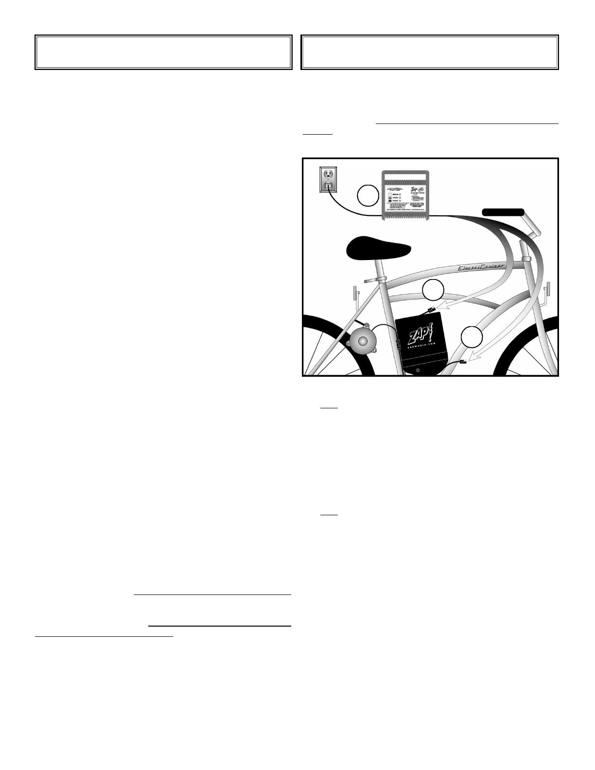
Charge the battery immediately after use in order to maximize
battery life. There are two ways to charge your battery. The ZAP
battery charger connects to the Battery Power Connector locat
-
ed on top of the battery, or the Auxiliary Power Jack located near
the battery tray. Using any other charger will damage the
battery.
To Connect Charger:
1. First connect the charger power connector to either the
Battery Power Connector or Auxiliary Power Jack.
2. Then, plug the ZAP charger into a standard 110 VAC wall
socket. NOTE: You can remove the battery and charge
away from the bicycle.
3. Please observe all safety warnings described on
pages 10-11.
To Disconnect Charger:
1. First, unplug the ZAP charger from the 110 VAC wall
socket.
2. Then, disconnect the Charger Power Connector from
the Battery Power Connector.
The 17 amp/hr battery will take at most three hours to fully
recharge. The light will flash between YELLOW and GREEN.
When fully charged, the GREEN
indicator light is lit most of the
time (6 seconds or more).
Regeneration
The ZAP Power System 2-speed system offers a regeneration
feature. This allows you to recharge your battery, by pedaling or
coasting, when wheel speed is greater than 11 mph with the
throttle switch on in low. The regeneration feature is most use
-
ful when descending hills. The regeneration feature will provide
up to 40 amps of current to your battery depending on your
speed.
In order to regenerate while riding, follow the steps below:
1. Place the cam lever in the down position (Cam engaged).
2. Keep the Throttle Switch to the low speed
3. Keep the wheel speed above 11 mph.
OPERATIONS AND FEATURES CHARGING
CHARGE AFTER EVERY USE!
2
1
1
11
PRE-OPERATIONAL SAFETY WARN-
INGS 1. Read and understand this owner’s
manual carefully before using this unit. Be
thoroughly familiar with the proper use of
your ZAP Power System.
2. Thoroughly inspect your ZAP Power System for loose
or damaged parts before each use. If there are any
loose or damaged parts, perform the needed adjust-
ments or repairs before starting your ZAP Power
System.
GENERAL WARNINGS
1. Do not smoke while operating the ZAP
Power System. Keep ZAP Power System
away from open flames such as pilot lights,
cigarettes, etc.
2. In order to prevent damages or injuries, do not attempt
to regenerate a fully charged battery.
3. The ZAP Power System is an electrical assistance for
your leg power. Overloading the motor will cause the
motor to shut off. This may happen when climbing hills,
crossing traffic or during any situation. Ride your bicycle
in such a manner that the electrical assistance is not
necessary for maintaining control of the bicycle. Always
be prepared for the sudden loss of electrical assistance.
Also, the rider must know and obey all local laws con-
cerning the operation of, and equipment requirements
of, electrically assisted bicycles. Make sure that your
equipment and operation of your electrically assisted
bicycle meets these standards. Failure to obey these
laws may result in severe injury or death.
4. AVOID UNINTENTIONAL STARTING - Do not leave
the ZAP Power System with the master “on/off” switch
ON when not in use. For greater safety disconnect
Battery Power Connector.
5. DO NOT disassemble the motor controller. Return the
ZAP Power System to your authorized service dealer
for service or repair.
BATTERY WARNINGS
1. To reduce the risk of injury, use only ZAP
batteries. Other batteries may explode
causing personal injury and damage.
2. DO NOT PLACE THE BATTERY NEAR FIRE OR
HEAT. IT COULD EXPLODE.
3. Batteries can emit explosive gases while being
charged. Do not obstruct the vents on the battery
container. Read the instructions supplied with your
charger before attempting to charge your battery.
CHARGER WARNINGS
1. Before using the battery charger, read all
instructions and cautionary markings in this
manual on the battery charger and the ZAP
Power System using the battery charger.
2.
USE ONLY THE CHARGER PROVIDED WITH YOUR
ZAP Power System. Do not substitute any other
charger. Use of any other charger could cause the
battery to explode, causing serious injury.
3. Do not expose charger to moisture and water.
4.
To reduce the risk of damage to the charger and cord,
pull the charger by the plug rather the cord when
disconnecting the charger.
5. Make sure the cord is located so that it will not be
stepped on, tripped over, or otherwise subject to
damage or stress.
6. An extension cord should not be used unless
absolutely necessary. Use of improper extension cords
could result in risk of fire and electric shock.
If an extension cord must be used, make sure:
a.
The pins on the plug of the extension cord are the
same number.
b. The extension cord is properly wired and in
good electrical condition.
c. The wire size is large enough for the AC ampere
rating of the charger as specified below.
7. DO NOT OPERATE CHARGER WITH A DAMAGED
CORD OR PLUG. If the cord or plug is damaged,
replace the charger.
8. Do not operate the charger if it has received a sharp
blow, been dropped, or damaged in any way. If the
charger case is damaged, replace the charger.
THE PURPOSE OF SAFETY SYMBOLS IS TO ATTRACT YOUR ATTENTION TO
POSSIBLE DANGERS. THE SAFETY SYMBOLS, AND THE EXPLANATIONS
WITH THEM , DESERVE YOUR CAREFUL ATTENTION AND UNDERSTANDING.
THE SAFETY WARNINGS BY THEMSELVES DO NOT ELIMINATE ANY DAN-
GER. THE INSTRUCTIONS OR WARNINGS THEY GIVE ARE NOT SUBSTI-
TUTES FOR PROPER ACCIDENT PREVENTION MEASURES.
WARNING: Failure to obey a safety
warning can result in injury to yourself or
others. Always follow the safety precau-
tions to reduce the risk of fire, electric
shock and personal injury.
SAFETY WARNINGS
12
RECOMMENDED WIRE SIZE (AWG) FOR GIVEN WIRE LENGTH
FEET 25 50 100
AWG 14 12 10
9. Do not disassemble the charger. The charger is not
serviceable; disassembly may result in a risk of electric
shock or fire.
10. To reduce the risk of electric shock, unplug the charger
from the outlet before attempting any cleaning of the
charger.
11. Do not use charger outdoors in wet conditions.
12. Charge in a well-ventilated area away from sparks,
flames and smoking areas.
13. For optimum performance, your ZAP Power System
should be charged in a location where the temperature
is more than 50° F (10° C) but less than 100° F (37° C).
(See “Battery Care on page 14.)
OPERATIONAL SAFETY WARNINGS
1. Keep hands, face, feet, and long hair
away from all moving parts.
2. Do not attempt to touch the motor while it is rotating.
3. Always remain alert. To prevent injury to yourself and
to others, do not operate your ZAP Power System if you
are fatigued or on medication.
4. Do not operate your ZAP Power System while under the
influence of drugs, alcohol, or medication.
5. Some states require that all bicycle riders wear a
safety helmet. It is recommended that this precaution
be followed at all times for maximum safety protection.
6. Never ride at night without functioning rear and front
lights, and all safety reflectors on your bike.
7. Be sure all wire connections, especially all battery
connections, are tight.
8. Follow all federal, state, and local laws regarding
electric bicycles.
OTHER SAFETY WARNINGS
1. Keep your ZAP Power System in good
working condition. Only your authorized
service dealer should perform any repair or
maintenance procedures that are not
described in this manual. Call (707) 824-4150 for your near
-
est dealer.
2. Use only original equipment manufacturer’s
replacement parts when servicing this ZAP Power
System. These parts are available from your
authorized service dealer. The use of non-standard
parts, or other accessories or attachments not designed
for this ZAP Power System, could result in serious injury
to the user and/or damage to the ZAP Power System.
3. STORE UNIT INDOORS - When not in use, the ZAP
Power System should be stored In a cool, dry place -
out of reach of children.
4. IMPORTANT! Before storing or ship-
ping your ZAP Power System be sure
to disconnect your Battery Power
Connector. Remove your battery from
the bicycle and store it in a FULLY
CHARGED CONDITION and away from any objects
that may short the battery terminals or Battery Power
Connector.
IT IS EXTREMELY IMPORTANT THAT YOU FOLLOW
THE SAFETY GUIDELINES CONTAINED IN THIS MANU
-
AL IN ORDER TO INSURE MAXIMUM SAFETY. FAILURE
TO COMPLY WITH THE STANDARDS OUTLINED IN
THIS MANUAL COULD RESULT IN FIRE AND/OR SERI
-
OUS INJURY. ZAP POWER SYSTEMS (ZAP) IS NOT IN
ANY WAY RESPONSIBLE OR LIABLE FOR ANY DAM
-
AGE OR INJURIES CAUSED BY UNSAFE OR FAULTY
REPAIRS. ANY REPAIRS MADE TO THIS PRODUCT BY
UNAUTHORIZED SERVICE TECHNICIANS ARE THE
SOLE RESPONSIBILITY OF THE OWNER.
SAFETY WARNINGS
CONTINUED
13
It is a good idea to periodically go
through this checklist to make sure that
your ZAP Power System and your bike
are in proper adjustment for safety and
optimal performance. It is imperative
that you review this checklist before
your first ride. Although your
PowerBike
®
or ElectriCruizer
®
has
passed our Quality Assurance proce-
dure, things can happen during ship-
ping which may alter the adjustment of
the system.
1. Check Tire Pressure: The tires on your
PowerBike
®
should be at their maximum tire pres-
sure (65 PSI-pounds per square inch), and the
tires on your ElectriCruizer
®
should be at 40 PSI.
If you installed a kit on your own bike, then check
to see that the tire pressure is at the recommend-
ed value for the tires you have.
2. Check Motor Alignment: Make sure
the roller is centered on the tire so that there isn’t
a possibility of one of the motors rubbing against
the tire. If it needs adjustment, simply loosen the
motor mount bolts, center the system and re-tight-
en. Wheels should be running straight & true.
3. Check Motor Engagement: Make sure
that the roller engages and compresses the tire by
approximately 1/16” when the cam lever is in the
down position. If it is more or less, loosen the
motor mount bolts and adjust by moving the sys-
tem up (if more than 1/16”) or down (if less than
1/16”). Then re-tighten the motor mount bolts.
4. Check Brake Pad Alignment:
Make
sure your front and rear brake pads are not rub
-
bing the rim, tire or spokes. If they are, we rec
-
ommend having them adjusted by a professional
bike mechanic at a bicycle store.
5. Check Battery Tray Stability:
Make
sure the battery is properly secured to the tray.
Attach the Velcro flaps to the sides of the Battery
Tray. Route the strap under the battery tray and
thread through the “D” ring. With the battery
secure, check to see that the tray is properly fixed
to the bike by trying to move the battery and tray
a bit. Tighten the two worm drive clamps if they
need tightening, but be sure not to over tighten
(which may strip the clamps).
6. Be sure all wire connections, espe-
cially battery terminals, are tight.
7. On the PowerBike, check the Quick
Release levers on both wheels.
8. Wear your ANSI or Snell-approved
helmet.
9. Use front and rear lights when
riding at night, and be sure all
reflectors are properly affixed.
Now you are ready, so
have a good ride!!!
Pre-Ride Checklist
q
ü
q
ü
q
ü
q
ü
q
ü
q
ü
q
ü
14
q
ü
q
ü
Battery Care
To ensure your new ZAP battery gives its best performance,
these following suggestions must be followed.
1)
Your ZAP Power System should be stored and charged at temperatures between 50° F (10° C) and 100° F (38° C).
2) Keep your battery charged. Batteries stored for long periods of time will self-discharge. The higher the
temperature, the greater the rate of self-discharge.
3) Keep the terminals clean and tight.
4) Handle it with care (don’t drop it).
5) Recharge your battery as soon as you can after riding. The ZAP battery will take 4-10 cycles of riding and
charging to bring the battery up to its full potential. Greater depth of discharge on a continual basis will
diminish the overall life of the battery (see charts below).
BATTERY PACK REPLACEMENT
Batteries must be recycled. To preserve natural resources, please recycle or dispose of properly. Local, state or federal
laws may prohibit disposal of lead-acid batteries in ordinary trash. Consult your local waste authority for information
regarding available recycling and/or disposal options.
REPLACING THE BATTERY
When the battery needs to be replaced, we recommend that you contact your nearest ZAP authorized dealer.
BATTERY PREPARATION
FOR RECYCLING
WARNING
Upon the removal of the battery, cover
the terminals with heavy duty adhesive
tape. Do not attempt to destroy or dis
-
assemble battery pack or remove any of its components.
Also, never touch both terminals with metal objects
and/or body parts as short circuit may result. Keep away
from children. Failure to comply with these warnings
could result in fire and/or serious injury.
15
115 ° F
46 ° C
104 ° F
40 ° C
77 ° F
25 ° C
32 ° F
0 ° C
5 ° F
-15 ° C
Temperature Effects on Battery Capacity
0
20
40
60
80
100
120
Temperature
THIS PRODUCT CONTAINS A SEALED LEAD-ACID
BATTERY. IT MUST BE RECYCLED
OR DISPOSED OF PROPERLY.
RECYCLE
Pb
Remember: Charge fully immediately after every each use
16
Troubleshooting Guide
Read the following section carefully. This guide will help your ZAP Power System achieve maximum
performance. If you cannot adjust your electric bike using this guide, call ZAP at (707) 824-4150.
Our customer service representatives will be glad to help you.
Possible Cause
Low tire pressure
Insufficient rider input
Over-engaged roller (greater than 1/16”)
Poorly tuned bike
Battery is not “broken in”
Cold battery
Battery not fully charged
Heavy rider
Damaged battery
Wrong type of tire
Improper critical setup distance or
motor position
Wet roads
Tire pressure low
Power switch is in off position
Loose wire connections
Battery is drained
Electrical fault in wiring
Only one motor connected
Motor controller leads reversed
Circuit breaker has tripped
A) Motor speed setting too
high for hill incline
B) Inadequate rider
input (pedaling) for incline
Action to be Taken
Inflate to maximum tire rating
Pedal more while riding
(especially when starting)
Check Easy Installation Guide
Tune brakes, bearings, true wheels
(If you don’t know how to tune your bike
correctly, bring your bike to a local bike
mechanic)
Charge, use, charge 4-10 times
before optimum range
Keep them warm or indoors when stored
and charging
Keep battery in fully charged condition
Order dual battery upgrade
Replace battery
Use only semi-slick tire
Readjust motor position
(see page 7)
Engage cam lever
Add air to maximum tire rating
Push switch on the left side of the
battery tray to ON position
(Push button until it clicks)
Check, tighten all connections
Charge battery immediately
Check all wiring connections
(battery terminals, motor leads, etc.)
Plug in second motor
Switch leads
Release throttle, wait 10 seconds
Use low speed setting
Pedal more
Problem
Insufficient Range
Drive Roller Slips
(Note: Roller should
never slip against tire)
Motor Does Not Start
Motor Runs Only on High
Motor Runs in Reverse
Motor Shuts off During Use
ALWAYS WEAR A HELMET WHEN RIDING
Pedals 350 in. lbs.
Seat Post Bolt Clamp 75-100 in. lbs.
Seat Clamp
Single Bolt 120-145 in. lbs.
Double Bolt 72-96 in. lbs.
Headset Topnut 300 in. lbs.
Handlebar Binder Bolt 175-260 in. lbs.
Hub Axle Locknut 88-220 in. lbs.
Cassette Lockrings 300-440 in. lbs.
Front Axle Nuts
(wheel mount) 180-240 in. lbs.
Rear Axle Nuts
(wheel mount) 240-300 in. lbs.
Quick Release
To Tighten: Not more than 45 lbs.
pressure at 55mm
from pivot
To Release: 12-25 lbs. pressure
Brake Arch
Attaching Bolt 70-85 in. lbs.
Shoe Bolt 43-60 in. lbs.
Cable Bolt 50-70 in. lbs.
Toe Clip Bolts 22 in. lbs.
Cantilever Brake
Frame Bolt 43-60 in. lbs.
Shoe Bolt 50-75 in. lbs.
Cable Carrier Nut 50-70 in. lbs.
Brake Lever Clamp
Screwdriver 22-30 in. lbs.
Hex Wrench 50-70 in. lbs.
Bottom Bracket Fixed
Cup & Lockring-Steel
Bottom Bracket 600-690 in.lbs.
(Alloy bottom bracket see manufacturer)
Chainwheel Bolts 70-95 in. lbs.
Crank Arm Bolt 350 in. lbs.
Shift Lever Clamp Bolt
Screwdriver 22-26 in. lbs.
Hex Wrench 44-52 in. lbs.
Rear Derailleur
Hanger Bolt 70-85 in. lbs.
Cable Bolt 45-60 in. lbs.
Front Derailleur
Clamp Bolt 45-60 in. lbs.
Cable Bolt 45-60 in. lbs.
Torque Ratings
CONVERSION INSTRUCTIONS
Tightening Specifications
Multiply By To Get
Foot pounds 12 Inch pounds
Foot pounds 1.355 Nm
Foot pounds 13.826 Kgf-cm
Inch pounds 0.083 Foot pounds
Inch pounds 0.113 Nm
Inch pounds 1.152 Kgf-cm
Nm 0.738 Foot pounds
Nm 8.857 Inch pounds
Nm 0.098 Kgf-cm
Kgf-cm 0.072 Foot pounds
Kgf-cm 0.868 Inch pounds
Kgf-cm 10.204 Nm
ZAPWORLD.COM • One ZAP Drive
117 Morris Street, Sebastopol CA 95472 USA
tel (707) 824-4150 fax (707) 824-4159
e-mail: [email protected] • Stock Symbol:ZAPP
ZAP is a Publicly Traded Company
ZAPWORLD.COM
where transportation is going
©2001 ZAPWORLD.COM. All rights reserved.
ZAP
®
is a registered trademark.
  • Page 1 1
  • Page 2 2
  • Page 3 3
  • Page 4 4
  • Page 5 5
  • Page 6 6
  • Page 7 7
  • Page 8 8
  • Page 9 9
  • Page 10 10
  • Page 11 11
  • Page 12 12
  • Page 13 13
  • Page 14 14
  • Page 15 15
  • Page 16 16
  • Page 17 17
  • Page 18 18
  • Page 19 19
  • Page 20 20
  • Page 21 21
  • Page 22 22

Zap DX User manual

Type
User manual

Ask a question and I''ll find the answer in the document

Finding information in a document is now easier with AI