Page is loading ...

PC-HELPER
Pt100 Thermo-sensor Input Module
for USB2.0
PTI-4(USB)
User’s Guide
CONTEC CO.,LTD.

PTI-4(USB)
i
Check Your Package
Thank you for purchasing the CONTEC product.
The product consists of the items listed below.
Check, with the following list, that your package is complete. If you discover damaged or missing items,
contact your retailer.
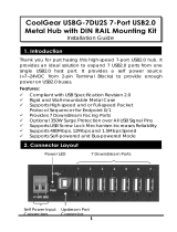
Product Configuration List
- USB module [PTI-4(USB)]…1
- First step guide …1
- CD-ROM *1 [API-USBP(WDM)]…1
- Interface connector (plugs) FK-MC0.5/9-ST-2.5 (mounted on the module)…2
- AC adapter (1.5m)…1
- AC cable (1.5m)…1
- USB cable (1.8m)…1
- Rubber feet…4
- Magnet…2
*1 The CD-ROM contains the driver software and User’s Guide (this guide)
Magnet
First step guide
AC adapter
USB cable
CD-ROM
[API-USBP(WDM)]
AC cable
Rubber feet
USB module
0
2
4
5
6
7
9
A
C
E
F
8
0
2
4
5
6
7
9
A
C
E
F
8
1
2

ii
PTI-4(USB)
Copyright
Copyright 2005 CONTEC CO., LTD. ALL RIGHTS RESERVED.
No part of this document may be copied or reproduced in any form by any means without prior written
consent of CONTEC CO., LTD.
CONTEC CO., LTD. makes no commitment to update or keep current the information contained in this
document. The information in this document is subject to change without notice.
All relevant issues have been considered in the preparation of this document. Should you notice an
omission or any questionable item in this document, please feel free to notify CONTEC CO., LTD.
Regardless of the foregoing statement, CONTEC assumes no responsibility for any errors that may appear
in this document or for results obtained by the user as a result of using this product.
Trademarks
F&eIT is a registered trademark of CONTEC CO., LTD. Other company and product names mentioned
herein are generally trademarks or registered trademarks of their respective owners.

PTI-4(USB)
iii
Table of Contents
Check Your Package................................................................................................................................i
Copyright.................................................................................................................................................ii
Trademarks..............................................................................................................................................ii
Table of Contents...................................................................................................................................iii
1. BEFORE USING THE PRODUCT 1
1.1. About the Module ............................................................................................................................1
1.1.1. Features ..................................................................................................................................2
1.1.2. Support Software ...................................................................................................................5
1.1.3. Accessories (Option) .............................................................................................................5
1.2. Customer Support ............................................................................................................................6
1.2.1. Web Site.................................................................................................................................6
1.3. Limited One-Year Warranty............................................................................................................6
1.4. How to Obtain Service.....................................................................................................................6
1.5. Liability............................................................................................................................................6
1.6. Safety Precautions............................................................................................................................7
1.6.1. Safety Information.................................................................................................................7
1.6.2. Handling Precautions.............................................................................................................7
1.6.3. Environment...........................................................................................................................9
1.6.4. Inspection...............................................................................................................................9
1.6.5. Storage....................................................................................................................................9
2. MODULE NOMENCLATURE 11
3. SETUP 13
3.1. Connection-Overall Diagram ........................................................................................................13
3.2. Setting a Module ID.......................................................................................................................13
3.3. Setup Flow .....................................................................................................................................14
3.4. Software Installation......................................................................................................................14
3.4.1. Illustration of Menu Screen................................................................................................14
3.4.2. Installation of API-USBP(WDM) Development Environment .........................................15
3.5. Connecting to a PC ........................................................................................................................16
3.6. Setting Properties Using Device Manager....................................................................................18
3.7. Connecting to an External Device.................................................................................................20
3.7.1. Signal Layout.......................................................................................................................20
3.7.2. Connection Method .............................................................................................................21
3.8. Connecting an External Power Supply .........................................................................................23

iv
PTI-4(USB)
3.9. Installing
the Module .....................................................................................................................25
3.9.1. Installation Orientation ........................................................................................................25
3.9.2. Mounting with magnets .......................................................................................................26
3.9.3. Mounting on a DIN Rail ......................................................................................................27
3.10. Using Several Modules with the same Model.............................................................................29
3.10.1. Setting a Module ID...........................................................................................................29
4. APPLICATION DEVELOPMENT 31
4.1. Reference to Online Help...............................................................................................................31
4.2. Printing Function Reference ..........................................................................................................31
4.3. Sample Program .............................................................................................................................32
4.4. Distributing Developed Application..............................................................................................32
5. TROUBLESHOOTING 33
5.1. Troubleshooting..............................................................................................................................33
5.2. Q&A................................................................................................................................................34
5.3. Diagnostic Program........................................................................................................................35
5.4. Version Upgrade.............................................................................................................................36
5.4.1. How to Upgrade the Firmware ............................................................................................36
5.4.2. Driver Upgrade.....................................................................................................................37
5.5. Returning to Initial State................................................................................................................37
6. CONNECTING WITH EXPANSION ACCESSORIES 41
6.1. Setting a Device ID ........................................................................................................................42
6.2. Connection between Modules........................................................................................................43
6.2.1. Stack Connection Locking Devices.....................................................................................43
6.2.2. How the Stack Connection Locking Device Works ...........................................................43
6.2.3. Connecting the Module........................................................................................................44
6.2.4. Removing the Module..........................................................................................................44
7. PRODUCT SPECIFICATION 45
7.1. Hardware Specification..................................................................................................................45
7.2. Software Specification ...................................................................................................................46
7.3. Circuit Block Diagram...................................................................................................................47
7.4. Physical Dimensions ......................................................................................................................48
8. APPENDIX 49
8.1. Glossary..........................................................................................................................................49

1. . Before Using the Product
PTI-4(USB)
1
1.
Before Using the Product
1.1. About the Module
Before, the measurement and control was realized by way of inserting PCI interface boards into expansion
slots of a desktop computer in case of configuring system using computers. However, because of the limit
on number of expansion slots, it is difficult to configure system sometimes, or it is difficult to perform the
same measure and control as PCI interface boards for a note PC. The USB module can be used to resolve
that kind of problems.
The PTI-4(USB) is a compact, ready-to-use module for collecting resistance and temperature data from a
USB-compatible platinum resistance temperature detector, Pt100 or JPt100.
This module can be used in various operating environments as it provides discontinuity detection and
digital filtering features.
It can be used by PC with USB interface and is for note PC best.
When using it on a desktop computer, you can perform simple connection without the need for opening
the host cover.
Being connected with USB port, the USB module can be setup simply. In addition, it can be
used immediately owing to the supplied Windows development environment and Utility.
The communication in Full Speed (12Mbps) is added to this USB module, and which is
compatible with High Speed (480Mbps). High Speed is namely High-Speed data
communication which is additional definition in the specification of USB2.0. The host
controller performs communication in 480Mbps when corresponding to High Speed of
USB2.0. Comparing with communication in Full Speed, the response for module access as
communication in High Speed improves.
Corresponding to USB
Desktop Computer Note PC
Easy to setup
Simple on utilization

1. . Before Using the Product
2
PTI-4(USB)
1.1.1. Features
¾
Supporting a variety of temperature measurement applications
Providing the averaging and alarm output functions as well as resistance/temperature data acquisition for
temperature measurement, thereby supporting various application.
Serviceable with either a three-wire or four-wire platinum resistance temperature detector.
- Resistance/temperature data acquisition
Capable of acquiring resistance data from a platinum resistance temperature detector connected.
While the output from the platinum resistance temperature detector is nonlinear with respect to
temperature changes, the module internally linearizes the input to obtain data as temperature values.
- Averaging by count
Capable of averaging data input after input data by sampling count.
- Averaging by time
Capable of averaging input data by
- Alarm output
Capable of sensing an alarm output upon detection of
a temperature outside the set temperature range. The
module can be programmed to take action only when
the alarm output changes. The alarm output can be
set for each channel.
The alarm output range can be set with four levels:
higher high limit, high lower limit, lower high limit,
and lower low limit.
¾
Digital Filter
Incorporating a digital filter for eliminating noise from the commercial power supply (50/60 Hz).
Note that the digital filter can be used only at a conversion speed of 150 ms.
¾
Discontinuity detection
Capable of detecting the discontinuity in a resistance temperature detector or conductor per channel.
¾
Isolated from external device
Using an opto-coupler to isolate the CPU in the module from the external device, preventing the
external device from electrically affecting the host computer directly via the USB port.

1. . Before Using the Product
PTI-4(USB)
3
¾
Easy to wire
The system incorporates a scrawls connector plug
that allows you to easily attach and detach wires
without using any special tools.
Press this section to
insert the wire
¾
Easy-to-install design
The system, in the module itself, incorporates a
35mm DIN rail mounting mechanism as a standard
item, so it can be attached and detached easily.
0
2
4
5
6
7
9
A
C
D
E
F
8
0
2
4
5
6
7
9
A
C
D
E
F
8
1
2
¾
Easy to extend input channel
By adding expansion modules Option, the number of
input channels can be increased.
It adopts the unique configuration of stack
connecting which permits a simple, compact system
configuration.
PTI-4(USB) + PTI-4(FIT)GY x 5
(Up to 24 input channels can be extended)
¾
Easy-to-develop-application Sample Program
Visual Basic, Visual C++, Delphi and C++ Builder
sample programs have been prepared.
Functions convenient for developing generic
applications, such as the functions that acquire the
list of the current available USB modules, are
prepared.

1. . Before Using the Product
4
PTI-4(USB)
¾
Convenient utility for debugging
- Diagnostic Program
When the problem occurred, it will be helpful to
solving the problem.

1. . Before Using the Product
PTI-4(USB)
5
1.1.2. Support Software
It is suggested that support software produced by our company should be used according to the goal and
development environment.
API Functions Library API-USBP(WDM) (Bundled)
It is the library software, and which supplies command of hardware produced by our company in the form
of standard Win32 API function(DLL). Using programming languages supporting Win32API functions,
such as Visual Basic and Visual C/C++ etc., you can develop high-speed application software with feature
of hardware produced by our company.
In addition, you can verify the operation of hardware using Diagnostic programs.
It also supplies the up-to-date driver and download service for missing files.
Further details may be found in the help within supplied CD-ROM or the homepage of our company.
< Operating Environment >
Primary corresponding OS Windows Vista, XP, Server 2003, 2000, Me, 98
Primary corresponding language Visual Basic, Visual C++, Visual C#, Delphi, C++ Builder
1.1.3. Accessories (Option)
Input Module for Pt100 Thermo-sensor : PTI-4(FIT)GY
(Expansion module for PTI-4(USB))
AC adapter (input: 90 - 264VAC, output: 5VDC 2.0A) : POA200-20
AC-DC power supply unit (input: 85 - 132VAC, output: 5VDC 3.0A) : POW-AD13GY
AC-DC power supply unit (input: 85 - 264VAC, output: 5VDC 2.0A) : POW-AD22GY
AC-DC power supply unit (input: 10 to 30VDC, output: 5VDC 3.0A) : POW-DD10GY
DC-DC power supply unit (input: 30 to 50VDC, output: 5VDC 3.0A) : POW-DD43GY
* Further details of the accessories may be verified in the Web site of our company.

1. . Before Using the Product
6
PTI-4(USB)
1.2. Customer Support
CONTEC provides the following support services for you to use CONTEC products more efficiently and
comfortably.
1.2.1. Web Site
Japanese http://www.contec.co.jp/
English http://www.contec.com/
Chinese http://www.contec.com.cn/
Latest product information
CONTEC provides up-to-date information on products.
CONTEC also provides product manuals and various technical documents in the PDF.
Free download
You can download updated driver software and differential files as well as sample programs available in
several languages.
Note! For product information
Contact your retailer if you have any technical question about a CONTEC product or need its price,
delivery time, or estimate information.
1.3. Limited One-Year Warranty
CONTEC F&eIT products are warranted by CONTEC CO., LTD. to be free from defects in material and
workmanship for up to one year from the date of purchase by the original purchaser.
Repair will be free of charge only when this device is returned freight prepaid with a copy of the original
invoice and a Return Merchandise Authorization to the distributor or the CONTEC group office, from
which it was purchased.
This warranty is not applicable for scratches or normal wear, but only for the electronic circuitry and
original products. The warranty is not applicable if the device has been tampered with or damaged
through abuse, mistreatment, neglect, or unreasonable use, or if the original invoice is not included, in
which case repairs will be considered beyond the warranty policy.
1.4. How to Obtain Service
For replacement or repair, return the device freight prepaid, with a copy of the original invoice. Please
obtain a Return Merchandise Authorization number (RMA) from the CONTEC group office where you
purchased before returning any product.
* No product will be accepted by CONTEC group without the RMA number.
1.5. Liability
The obligation of the warrantor is solely to repair or replace the product. In no event will the warrantor be
liable for any incidental or consequential damages due to such defect or consequences that arise from
inexperienced usage, misuse, or malfunction of this device.

1. . Before Using the Product
PTI-4(USB)
7
1.6. Safety Precautions
Understand the following definitions and precautions to use the product safely.
1.6.1. Safety Information
This document provides safety information using the following symbols to prevent accidents resulting in
injury or death and the destruction of equipment and resources. Understand the meanings of these labels
to operate the equipment safely.
DANGER
DANGER indicates an imminently hazardous situation which, if not avoided, will
result in death or serious injury.
WARNING
WARNING indicates a potentially hazardous situation which, if not avoided, could
result in death or serious injury.
CAUTION
CAUTION indicates a potentially hazardous situation which, if not avoided, may result
in minor or moderate injury or in property damage.
1.6.2. Handling Precautions
DANGER
Please do not use the product in environments subject to flammable and corrosive gas. Otherwise, it
can bring on exploding, fire, electric shock and trouble.
CAUTION
- There are switches on the module that need to be set in advance.
Be sure to check its switch settings before using the module.
- Please do not change the module switch settings in an unauthorized manner.
Otherwise, it can bring about malfunction, heating and trouble.
- Please do not subject the module to impact or bend it.
Otherwise, it can bring about malfunction, heating, trouble and damage.
- Please do not touch the metallic pins on the external module connector.
Otherwise, it can bring about malfunction, heating and trouble.
- When you use the module in a noisy environment or are nervous about noise, attach ferrite cores to
the connection cable.
- Please do not connect expansion module when the power for the module is turned on.
Otherwise, it can bring about malfunction, heating and trouble.
Be sure to turn off the power for the USB module.
- If you notice any strange odor or overheating, please unplug the power cord and USB cable
immediately.
Otherwise, it can bring about malfunction, heating and trouble.
In the event of an abnormal condition or malfunction, please consult the dealer from whom the
product was purchased.

1. . Before Using the Product
8
PTI-4(USB)
- In order to add functions to the product and perform quality improvement, the product specification is
subject to change without notice.
Even if you use the product again, please be sure to read the manual to confirm the content.
- Please do not modify the product.
CONTEC will bear no responsibility for any problems, etc., resulting from modifying the product.
- Please do not open the product casing.
CONTEC will disclaim any responsibility for products whose casing has been opened.
- Regardless of the foregoing statement, CONTEC assumes no responsibility for any errors that may
appear in this document nor for results obtained by the user as a result of using this product.
- It may cause a trouble in recognizing and operating the device according to the kind of USB hub. If
you use the USB hub, we encourage you to take advantage of the CONTEC’s product loan service to
confirm operation before purchasing.
- Regarding “EMC Instruction Class A Notice and VCCI Class A”
This product has acquired the above-mentioned standard.
However, a sufficient margin may not be secured for the standard. In such cases, use a ferrite core
(SEIWA E04SR301334 or a compatible product) for the USB cable (this product’s side).
When attaching the ferrite core, coil it around once near the connector while leaving it open, and then
close it.
As a rider to the EMC Directive for a Class A product, USB connector and DIN rail must be earthed.
FCC PART 15Class A Notice
This equipment has been tested and found to comply with the limits for a Class A digital
device, pursuant to part 15 of the FCC Rules. These limits are designed to provide reasonable
protection against harmful interference when the equipment is operated in commercial
environment.
This equipment generates, uses, and can radiate radio frequency energy and, if not installed
and used in accordance with the instruction manual, may cause harmful interference to radio
communications. Operation of this equipment in a residential area is likely to cause harmful
interference at his own expense.
NOTE
Change or modifications not expressly approved the manufacturer can void the user's
authority to operate this equipment.
WARNING TO USER

1. . Before Using the Product
PTI-4(USB)
9
1.6.3. Environment
Use this product in the following environment. If used in an unauthorized environment, the module may
overheat, malfunction, or cause a failure.
Operating temperature
0 - 50
°C
Operating humidity
10 - 90%
RH (No condensation)
Corrosive gases
None
Floating dust particles
Not to be excessive
1.6.4. Inspection
Inspect the product periodically as follows to use it safely.
0
2
3
4
5
6
7
9
A
C
D
E
F
8
0
2
3
4
5
6
7
9
A
C
D
E
F
8
1
2
*Make sure that the connectors on the module side are correctly
connected with the cables
*The ventilation slits are not covered,
and neither dust nor alien substance is attached to the ventilation slits
1.6.5. Storage
When storing this product, keep it in its original packing form.
(1) Put the module in the storage bag.
(2) Wrap it in the packing material, then put it in the box.
(3) Store the package at room temperature at a place free from direct sunlight, moisture, shock, vibration,
magnetism, and static electricity.

1. . Before Using the Product
10
PTI-4(USB)

2. . Module Nomenclature
PTI-4(USB)
11
2.
Module Nomenclature
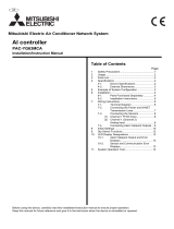
Figures 2.1 shows the names of module components.
In the figures, the indicated switch settings represent factory settings.
LINK status LED
Interface Connector
Sensor setting SW
Module ID
USB port
Status LED
Figure 2.1. Nomenclature of Module Components
*1 When you use the module in a noisy environment or are nervous about noise, ground the module (using a M3 screw).
Table 2.1. List of Status LED Functions
Name
Function Indicator
color
LED indicator
ON: Communication established
LINK status
USB
communication
status
GREEN
OFF: Communication unestablished
RUN status
Run status
GREEN
ON:
Upon completion of startup after the power is turned on
ERR status
Error status
RED
OFF:
Upon discontinuity detection or alarm output
Table 2.2. Settings of Sensor Setting Switches
SW setting Wiring method Platinum resistance temperature detector
ON
12
PT
3W
JPT
4W
Pt100 *1
ON
12
PT
3W
JPT
4W
Three-wire type
JPt100
ON
12
PT
3W
JPT
4W
Pt100
ON
12
PT
3W
JPT
4W
Four-wire type
JPt100
*1 Factory setting
*1

2. . Module Nomenclature
12
PTI-4(USB)

3. . Setup
PTI-4(USB)
13
3.
Setup
3.1. Connection-Overall Diagram
This is connection-overall diagram. Please reference to this page for actual connection.
Figure 3.1. Connection-Overall Diagram
3.2. Setting a Module ID
The host computer distinguishes and keeps track of the modules of same model by assigning Module IDs
to them. Factory settings “00” can be used when only one module per model is connected to one computer.
Each module should be assigned a unique Module ID in the range of 00 to 7Fh when several modules with
the same model are being connected. When the module is connected along with the CPU-CA10(USB)GY,
assign different module IDs to them.
There are two rotary switches, moreover, “x16” and “x1” represent high bits and low bits of Module
ID respectively.
Module ID 00h
[Factory Settings]
Module ID 12h
Module
ID(x16)
Module
ID (x1)
[0]
[0]
Module
ID(x16)
Module
ID (x1)
[1]
[2]
Figure 3.2. Setting a Module ID
Software Installation
(Page 14)
Connecting to a PC
(Page 16)
Connecting to an
External Device
(Page 20)
Connecting with
Expansion
A
ccessories
(Page 41)
Mounting on a DIN Rail
(Page 27)
0
2
3
4
5
6
9
A
C
D
E
F
8
0
2
3
4
5
6
9
A
C
D
E
F
8
1
2
1
2
0
4
0
4
6
2
5
1
3
7
PTI-4
Device
4W
JPT
3W
PT
ID
RUN ERR
b1
NC
CH1 a1
B1
A1
a0
CH0
A0
B0
b0
NC
b3
a2CH2
CH3
a3
B3
A3
A2
B2
b2

3. . Setup
14
PTI-4(USB)
3.3. Setup Flow
The following shows the basic flow for installing USB module.
3.4. Software Installation
Install software.
3.4.1. Illustration of Menu Screen
Point
- Please set up the supplied CD-ROM if it has not been set up. The menu starts automatically.
- If the menu do not start, launch X:AUTORUN.EXE(X:CD-ROM drive) from [Run…] in Start menu.
- The screen design may be different.
Setting Properties Using
Device Manager
- Setting device name
Page 14 Page 16
Page 18
Connecting to a PC
- Installing USB driver
Software Installation
- API-USBP(WDM)
Development Environment
Install the Development Environment
such as sample programs and online
help, etc.
Refer to the description about CD-ROM.
Install the utility.
Install the C-LOGGER.
*Cannot be used for this product.
Refer to the user’s manual.

3. . Setup
PTI-4(USB)
15
3.4.2. Installation of API-USBP(WDM) Development
Environment
Installation of development environment is namely installing supplied online help and sample program in
all language in order to use API function.
Step1 Clicking on “Install Development or Execution Environment”
[API-USBP(WDM) Installer]
dialog box displays.
Step2 Selecting “Advanced Temperature Sensor”
Step3 Clicking on “Install” Button
Please perform installation following the directions on the screen. And thus the installation is completed.
*The screen design may be different.
/