Page is loading ...

System Installation
Manual
www.ptisecurity.com 800.523.9504
114A3866.D Revised July 2017

ii 114A3866.C.05 Revised 7-2017
Thank you for purchasing the Falcon XT™ and StorLogix™ Access Control System. For your
complete satisfaction with this product, we recommend that you take the time to thoroughly
review this manual.
It is designed to be followed from start to finish for proper installation of the Falcon XT™
Access Control System. If you have any difficulties, we strongly recommend that you review this
manual prior to contacting Technical Support.
NOTE: This equipment has been tested and found to comply with the limits for a Class B digital device, pursuant to
Part 15 of the FCC Rules. These limits are designed to provide reasonable protection against harmful interference in
a residential installation. This equipment generates, uses, and can radiate radio frequency energy and, if not installed
and used in accordance with the instructions, may cause harmful interference to radio communications. However,
there is no guarantee that interference will not occur in a particular installation. If this equipment does cause harmful
interference to radio or television reception, which can be determined by turning the equipment off and on, the user
is encouraged to try to correct the interference by one or more of the following measures:
z Reorient or relocate the receiving antenna.
z Increase the separation between the equipment and receiver.
z Connect the equipment into an outlet on a circuit different from that to which the receiver is connected.
z Consult the dealer or an experienced radio TV technician for help.
This Class B digital apparatus complies with Canadian ICES-003.
Cet appareil numérique de la classe B est conforme à la norme NMB-003 du Canada.
© 2017 PTI Security Systems
All rights reserved.
No part of this publication may be reproduced, transmitted, transcribed, or translated into any
language in any form, by any means, without written permission of PTI Security Systems.
Falcon XT™, StorLogix™, “Security Without Limits”™, “Security, Access : Control”™,
LogixServer™, LogixScript™, VideoViewer™, EventViewer™, Site Graphics™,
“Easy to Implement, Simple to Use”™, are trademarks of PTI Security Systems. All rights
reserved.
Microsoft
®
Windows
®
, Adobe Reader
®
, Pentium
®
, McAfee Virus Scan
®
, Norton Antivirus
®
and all
other trademarks referenced are the property of their respective owners.

iii114A3866.D Revised 7-2017
This equipment generates, uses, and can radiate radio frequency energy and if not
installed and used in accordance with the instruction manual, may cause interference
to radio communications. It has been tested and found to comply with the limits for
a Class A computing device pursuant to Subpart J of Part 15 of FCC rules, which are
designed to provide reasonable protection against such interference when operated
in a commercial environment. Operation of this equipment in a residential area is likely
to cause interference in which case the user, at his/her own expense, will be required
to take whatever measures may be required to correct the interference.
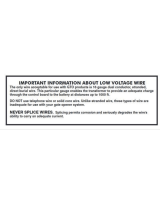
With the RS485 communication scheme, a keypad can be located as far as 4000 feet
from the controller, therefore shielded twisted pair cable with ground wire is required for
optimal operation. Additionally, larger gauge wire must be used the farther the device
is from the controller,
The system will not operate properly if the voltage is below 12VDC. Extreme
care should be taken when choosing a power supply voltage and current rating. Long
distance runs may require a remote power supply to be installed in line with an RB5
relay to ensure proper operation.
Do NOT run low voltage system wires in the same conduit as high voltage
wiring
Incorrect installation of electrical components can result in damage to
electronics as well as personal injury.
Cross-wiring the AC power with the DC power will damage the electronics.
Cross-Wiring the Power wires with the Data wires will damage the electronics
Cross-wiring the positive and negative on the DC part of the system will
damage the electronics.
Warning: The User should follow all installation, operation, and maintenance
instructions. The User is strongly advised to conduct product and systems tests at
least once each week. Changes in environmental conditions, electric or electronic
disruptions and tampering may cause the product to not perform as expected.
PTI Security Systems warrants its Product to the User. The User is responsible
for exercising all due prudence and taking necessary precautions for the safety and
protection of lives and property wherever PTI Security Systems products are installed.
PTI Security Systems does not authorize the use of its products in applications
affecting life safety.

iv 114A3866.C.05 Revised 7-2017
Contents
Overview ........................................................................................................................... 1
Specifications .................................................................................................................... 2
Computer System Requirements ....................................................................................... 3
Wire and Cable Specifications .......................................................................................... 6
AI Device Power & Data Wire Recommendation
(from Controller to AI Devices) ........................................................................................................... 6
Door Alarm Wire Recommendation
(from Multiplexer to Door Switch) ...................................................................................................... 7
Intercom Wire Recommendation
(from LEF or NEM Base Station to intercoms) .................................................................................... 7
Cameras/Video Wire Recommendations
(From DVR to Camera) ....................................................................................................................... 8
International Wire Cross-Reference ................................................................................................... 8
Surge Protection ................................................................................................................................ 9
Battery Operation ............................................................................................................ 10
Power Considerations...................................................................................................... 11
Amperage Calculation ..................................................................................................................... 11
Cable Voltage Loss .......................................................................................................................... 12
Calculate Voltage Drop .................................................................................................................... 13
Pre-Installation Recommendations .................................................................................. 14
Unpacking the Falcon XT ................................................................................................ 17
Typical Wiring Scheme .................................................................................................... 18
Installing the Falcon XT™ ............................................................................................... 21
Location ........................................................................................................................................... 21
Controller to Computer Connection ................................................................................................ 22
Controller to AI Devices Connection ............................................................................................... 25
Output Relay Connections ............................................................................................................... 27
Door Input Connections ................................................................................................................... 29
Wiegand Input Connections ............................................................................................................ 31
Power Connections (North America) ................................................................................................ 33
Power Connections (International) ................................................................................................... 35
Troubleshooting the Falcon XT ....................................................................................... 37
Reset the System .............................................................................................................................. 38
Standard One-Year Equipment Warranty ........................................................................ 40
Voltage Drop Calculations ............................................................................................... 41

1114A3866.D Revised 7-2017
Overview
The Falcon XT™ offers the access control industry the most comprehensive hardware and
software package to the access control industry. It's revolutionary design integrates surveillance,
access control, intrusion, lighting, custom scripting, and elevator controls all in one package.
• 8 inputs on the main board for door alarms, motion sensors, beams, or almost any other
type of alarm switch
• 4 output relays on the main board to open gates or doors, activate lights, control elevators,
shunt alarms, act as secure interior relays, or perform custom function switching
• 2 Wiegand Protocol Device inputs on the main board to connect proximity card devices,
key fob devices, biometric fingerprint devices, and many other types of Wiegand protocol
devices
• A built-in 12VDC 2A power supply with 5Ah battery backup
• Integrates with a computer using RS232, USB, or Ethernet TCP/IP
• Supports up to 127 Access Interface (AI) devices.

2 114A3866.C.05 Revised 7-2017
Specifications
Input Power:
Input Voltage: 24 VAC – 40 VA
24 VDC – 2.5 A
Output Power:
Output Voltage: 13.8VCD nominal
2A max load
Relay Specifications:
Maximum Switching Voltage*: 30VAC / 30VDC
Maximum Switching Current*: AC: 10A (NO) / 3A (NC)
DC: 5A (NO) / 3A (NC)
* Resistive load
Inputs:
Dry contact supervised inputs.
Environmental:
Ambient Temperature: -40°C to +85°C (-40°F to 185°F)
Ambient Humidity: 0% to 85% , non condensing
Note: The Falcon XT is not intended for outdoor installation.
See "Computer System Requirements" on page 3 for computers, components, and
peripherals used with the controller.

3114A3866.D Revised 7-2017
Computer System Requirements
PTI recommends that installation and setup of any PTI Security Systems equipment is done by
a certified, licensed, qualified technician. PTI can recommend local dealers and installers, but
it is the customers’ responsibility to verify qualifications and negotiate any pricing or contracts
(unless PTI Security Systems has been specifically contracted in writing to do so on behalf of the
customer).
Computers running any PTI Security Systems hardware, software, or utilities must meet these
computer requirements. These requirements are intended as a minimum guideline for operating
our access control system and are subject to change without notice.
With any computer setup or configuration, some troubleshooting and adjustment of the
configuration may be required. This will differ with every computer setup depending on operating
system, software installed on it, quality of components, internet connection, modem connection,
or any other variable introduced into the setup.
Troubleshooting and configuration may include the purchase of additional equipment. Under
no circumstances is PTI Security Systems be responsible for any damages either incidental
or consequential based on these recommendations If a customer intends to add third party
peripherals to the system, they are responsible for ensuring that the products are compatible
with the access control system they have installed.
NOTE: If you are using any other software as well as StorLogix™, ensure that your computer
specifications exceed the combined total requirements for all of the software loaded on the
computer.
StorLogix™ Computer Requirements
These computer requirements are the minimum for running the software by itself.
• 1.8GHz or higher processor
• 4+ GB RAM for StorLogix™
• 10+ GB available hard drive space
• DVD-ROM (with high capacity storage, such as a DVD-RW, available for backups)
• 800 x 600 minimum resolution monitor
• Sound card and speakers recommended
• One or more available working ports [Ethernet TCP/IP port(s), USB port(s), or RS232
port(s)]
• Broadband/high-speed business internet connection (cable, T1, or DSL), always-on
connection

4 114A3866.C.05 Revised 7-2017
• Keyboard and Mouse
• A high quality printer (for printing Reports)
• Remote access software for technical assistance (PTI uses FastSupport.com).
• Anti-virus software
• Firewall protection is strongly recommended (ensure settings do not interfere with other
applications running on the system). This should be setup by a knowledgeable computer
tech as some configuration may be required.
• UPS (Uninterruptible Power Supply) power backup and surge protection recommended.
Operating System
• 32-bit (x86) or 64-bit (x64)* Windows 7, SP1, 8, 8.1, 10.
• 32-bit (x86) or 64-bit (x64)* Windows Server 2008 SP2, 2008 R2 SP1, 2012, 2012 R2, or
higher.
• All necessary update and service packs for Windows should be loaded onto the computer
before starting installation.
• Windows XP is no longer supported. StorLogix™ 5.0 and higher will not run on this OS.
• StorLogix™ will NOT run on Mac or Linux
• DO NOT run StorLogix on a virtual machine or server.
* Not all operating systems support all software and some third party products (such as card
scanners, cameras,or other peripherals) may not function with some operating systems and/
or computers (i.e.,64-bit operating systems may not support peripherals built for use on 32-
bit or earlier platforms). Refer to the product manufacturer’s documentation for compatibility
information with the operating system in use. PTI Security Systems is not liable for the functioning
or reliability of any third party products. Any products recommended by PTI is done so based
on evidence of compatability with our product. PTI Security Systems does not guarantee any
third party product compatibility or continued functionality, future releases, updates, upgrades,
or other modifications to these products may affect their compatibility with PTI Security Systems
products or with other programs on your computer. We recommend that your computer and
network be regularly updated and maintained by a qualified information technology technician.
To receive technical support from PTI,
you MUST have remote access software installed on your PC.

5114A3866.D Revised 7-2017
Falcon XT Computer Interface Requirements
The following items are required for the operation of the access system controller.
• StorLogix™ software, version 4.1 or newer
• Ethernet, USB, or RS232 connection
- Ethernet Cable Connection — maximum length 328 feet (100m)
- USB Connection — If connecting using USB, the supplied USB isolator MUST be used
as it includes circuit protection. Failure to use this isolator will void your warranty. —
maximum length 16 feet (4.5m)
- RS232 Cable Connection — maximum length 50 feet (15m)
• Electrical outlet providing 120VAC (United States) or 240VAC (Europe or Australia)
Proximity Cards / Photo ID Badges / Swipe Cards
The following items are recommended for the operation of peripheral devices.
• Compatible Wiegand interface cards for proximity devices
• Any 4-line magnetic stripe card for use with swipe reader devices
Site Graphics™ Additional Requirements (optional)
If you have purchased the Site Graphics™ software the computer running the software must
include these computer requirements as well as those previously listed.
• PTI Graphics Serial Adapter (Part # PGRASIA)
• 16 MB Video Card or higher
• 1024 x 768 resolution minimum (Large screen monitor recommended)

6 114A3866.C.05 Revised 7-2017
Wire and Cable Specifications
The following wire specifications are recommended for installing PTI Security Systems' products.
Planning and installing the wiring of a site is a process that requires a high degree of technical
knowledge; we recommend that this be done by a trained professional.
PTI recommends that you purchase your wire from PTI Security Systems as our recommendations
are based on extensive experience with the Falcon XT. PTI verifies that, if installed correctly, the
wire will work with the security system.
AI Device Power & Data Wire Recommendation
(from Controller to AI Devices)
PTI Part #
Belden
Wire Code
Description
wwir1804s*
9418
18 AWG, 4-conductor stranded copper wire with overall
shield and common ground (PVC Insulation)
wwir1804spl 89418
18 AWG, 4-conductor stranded copper wire with overall
shield and common ground (Plenum Insulation)
wwir1804sdb 9552
18 AWG, 4-conductor stranded copper wire with overall
shield and common ground (Direct Burial)
* Denotes standard recommended wire.
• Never use wire smaller than 18 AWG for installing power to AI devices.
• Never use any unshielded wire for installing power and data to AI devices.
• Data wire length should never exceed 4000 feet in a single linear distance.
• Maximum length for power will vary significantly because of voltage drop due to current
draw, number of devices, splices, and other factors.
Using the wrong wire for an application can cause problems with voltage drop,
RF interference, and ground faults.
Always refer to local code prior to ordering the wire for your site,
as these requirements may be more stringent.

7114A3866.D Revised 7-2017
Door Alarm Wire Recommendation
(from Multiplexer to Door Switch)
PTI Part #
Belden
Wire Code
Description
wwir2450 * 9585 24 AWG, 50-conductor solid copper wire (PVC Insulation)
wwir2450pl N/A 24 AWG, 50-conductor solid copper wire (Plenum Insulation)
wwir2450db 165185110 24 AWG, 50-conductor solid copper wire (Direct Burial)
* Denotes standard recommended wire.
• Never use wire smaller than 24 AWG for installing door switches.
• Never use stranded wire for installing door switches.
• Applications that require shielded trunk line, use direct burial cable.
Intercom Wire Recommendation
(from LEF or NEM Base Station to intercoms)
PTI Part #
Belden
Wire Code
Description
wwir1810s * 5345FE
18 AWG, 10-conductor stranded copper wire with overall
shield and common ground (PVC Insulation)
wwir1804s * 9418
18 AWG, 4-conductor stranded copper wire with overall
shield and common ground (PVC Insulation)
wwir1802s 8760
18 AWG, 2-conductor stranded copper wire with overall
shield and common ground (PVC Insulation)
wwir2210s 9946
22 AWG, 10-conductor stranded copper wire with overall
shield and common ground (PVC Insulation)
* Denotes standard recommended wire.
• Never use wire smaller than 22 AWG for installing LEF or NEM intercoms. We recommend
that 18 AWG be used in most installations for best results. Do not exceed 1600 feet in
linear distance when using 18 AWG or 600 feet in linear distance using 22 AWG.

8 114A3866.C.05 Revised 7-2017
International Wire Cross-Reference
The chart below shows the nearest approximate wire equivalents for several international wire
gauge standards for use with PTI Security Systems products. It is usually better to use a slightly
thicker wire than a thinner one (especially over longer distances). Always refer to local electrical
codes and regulations as these requirements may be more stringent. Refer to the wire type
requirements on the previous pages for cross reference.
AWG
American Wire
Gauge
SWG/Imperial
British Standard
Gauge
Metric
Metric Wire Gauge
CSA
Cross-Sectional Area
16 18 or 17 14 2.50 mm
2
18 19 or 18 12 2.00 mm
2
20 21 9 or 8 1.50 mm
2
22 22 7 1.25 mm
2
24 24 6 1.00 mm
2
Surge Protection
All access control systems and electronics experience power fluctuations and surges, so the
controller has built-in surge protection. However if you are in an area that is prone to brownouts,
blackouts, electrical storms, or other major power interruptions or fluctuations, PTI recommends
that the system is equipped with the following safeguards against these problems.
• If using the USB to connect the Falcon XT™, you MUST use the USB isolator supplied as it
will provide the required surge protection. Failure to use the isolator for USB connectivity
will void your warranty.
• Use UL rated power supplies, rated to provide at least 12 volts to maximum 18 volts
(AC or DC) at each AI device. Power must provide sufficient amperage throughout the
system.
• Install an uninterruptable power supply (UPS) system. This provides power conditioning
and surge suppression to protect electronics. The controller and system power supplies
must be connected to separate UPSs from the computer. Each component plugged into
a UPS reduces the actual battery backup time.
• Ditek or Opto-Isolator surge protection for the RS232 and RS485 at the controller, and
Ditek or Opto-Isolator surge protection for the RS485 at each AI device..
• Gates, door strikes, and elevators should have battery backup or other safety measures
that meet local and national electrical codes. Consult with these specialist installers for
recommendations.

9114A3866.D Revised 7-2017
• Office computers, copiers, fax machines, telephones, and other electronics should be
plugged into surge protectors or a separate UPS.
• Obtain adequate lightning insurance coverage from an insurance agent for all electronic
equipment if you are in an area that is prone to regular lightning strikes or electrical
storms. Lightning is powerful enough to arc across the sky, there is not much that you
can do to protect any electrical equipment against a direct strike other than to have
appropriate lightning insurance.
• For ongoing power issues, contact your local electrical company for their recommendations.
Often, they can install power conditioners and/or surge suppressors on the incoming
power lines to help protect your site.
These recommendations should provide protection against most common power surges, power
fluctuations, indirect lightning strikes, and general electrical storm activity. Unfortunately, due to
the naturally destructive nature of lightning and electrical storms, there is only so much protection
that can be provided to any hard-wired electronic system. Any local or direct strike may damage
one or more pieces of electronic equipment in the vicinity and may damage or destroy the surge
protectors or even, in some cases, the entire system.
Battery Operation
When the Power Supply input power is interrupted, the Power Supply will automatically switch
to using the battery as the power source. Several factors will influence the amount of time that
the battery will keep the system operational including load, temperature, age of the battery,
minimum voltage requirement and charge state. The following chart can be used to estimate
backup time based on average current load.
Backup time
(hours)
Average Current Load
4AH
Battery
7AH
Battery
11 0.25A 0.35A
5 0.45A 0.63A
3 0.85A 1.2A
2 1.25A 1.75A
The battery life also depends on the same variables listed above but when used as a backup
function in PTI equipment, a battery may last 3-5 years.
For a security system battery backup function to be effective, any gate or door strike must also
have a separately powered battery backup. See more battery information in "Battery Maintenance
and Replacement Instructions:" on page 31

10 114A3866.C.05 Revised 7-2017
Power Considerations
The Falcon XT has a built-in battery backed power supply capable of outputting 2A DC for
powering AI devices and RS485 isolators connected to the Falcon XT’s RS485 network. The
output is available on P13, pins 1 and 2 labeled 12VDC and GND.
This output is controlled by the Falcon XT firmware and has the following characteristics:
• It is powered on after the XT initializes. This can be several seconds after a reset of the
Falcon XT before the power output is switched on.
• It is short circuit protected. When a short condition is detected power will be switched
off. The XT will retry enabling power periodically and switch it back on when the short
condition is removed.
• When operating on battery power, the Falcon XT will switch off the power output when
the battery voltage drops to 11 volts.
All the above conditions are recorded in the Falcon XT event log and can be viewed in StorLogix.
If additional power is required, external remote power supplies can be added to the system. For
guidance calculating the power requirements of the system, see the "Remote Power Supply"
manual. Here you will find detailed calculations for planning power distribution for your system.
Precautions:
Door strikes, magnetic locks and sirens must be powered from their own power
supplies. Do not power them from the same supply used to power the AI device.
The manuals for the products list their maximum current consumption. Always use
maximums when calculating voltage drop in your connecting cable.
PTI recommends planning for no more than 75% of the supplies load. For the
Falcon XT’s 2A supply we recommend connecting no more than a 1.5A load.

11114A3866.D Revised 7-2017
Pre-Installation Recommendations
Correct installation is essential to create a security system that operates properly. Reducing
installation costs may save you money in the short run, but your long term maintenance, costs
and experience with the system will be greatly improved if you spend the time and money to
install it correctly from the start. A poor installation can lead to increased costs due to loss of
revenue plus many technician hours to fix issues from the original setup.
Choice of Installer
PTI recommends that installation and setup of any PTI Security Systems equipment be done by
a certified, licensed, qualified technician. PTI can recommend local dealers and installers, but
it is the customers’ responsibility to verify qualifications and negotiate any pricing or contracts
(unless PTI Security Systems has been specifically contracted in writing to do so on behalf of the
customer).
With any setup or installation, some troubleshooting and adjustment of the configuration may
be required. This will differ with every installation due to site-specific variables. Troubleshooting
and configuration may include the purchase of additional equipment. PTI Security Systems is not
responsible for any damages either incidental or consequential based on these recommendations.
Code and Legal Considerations
Installation of equipment manufactured by PTI Security Systems must be performed per our
recommendations and guidelines except where local, municipal, state, and provincial codes; the
National Electrical Code; and Construction codes take precedence.
When code and our guidelines do not cover a given situation, it is the customer/installer’s
responsibility to contact PTI Security Systems for instruction and/or follow established custom
and best practices applicable to the particular trade. Installers must know and abide by all existing
laws pertaining to their work.
Meeting code is always the customer/installer’s responsibility and PTI Security Systems shall not
be held liable if the equipment is not installed to code.
Power
Reliable equipment operation depends on a noise-free uninterrupted source of power. The
battery back-up feature’s primary function is to preserve the integrity of the memory database
and operation of the controller.
• Verify that there are enough 120V outlets in the area where the equipment will be located
to support equipment needs. Each power supply, controller, computer, video monitor,
etc. requires at least one outlet

12 114A3866.C.05 Revised 7-2017
• PTI recommends a minimum of two, 4-outlet stations for the equipment. However your
site may require more.
• Remember to consider other office equipment and electronics that requires power (e.g.
copiers, fax machines, computers, telephones, lights, water coolers, etc.
The PTI battery back-up does not guarantee emergency operation of the gate motor, or door
actuators in the event of a power loss or equipment failure.
The purchaser is the solely responsible for providing manual, non-electrical emergency means of
exit in the event of a power failure. Contact your local dealer/installer for solutions.
Auxiliary Security Devices
Power for door strikes, gate operators, sirens, cameras and any other equipment must be
provided by separate power supplies from controller and AI devices.
Wire
• Refer to "Wire and Cable Specifications" on page 6 for the correct wire to use with
the controller.
• Plan for enough wire plus an additional 10% – 15% for safety.
• Plan for the linear distance, the distance in rise for multiple floors, or the distance in depth
for burial when ordering wire.
• Pull an extra 10 feet of wire at each end of a wire pull during installation. This allows for
enough wire to meet the needs of the site without making wire splices.
• When installing AI devices, trim the excess wire, leaving a one-foot service loop.
• Pull an extra 18 AWG 4-conductor wire throughout the site and set aside extra sets of 24
AWG 50-conductor wires for future add-ons, maintenance, or repair of wiring. This is less
expensive and easier to do during install than to try and pull wire later.
• PTI Security Systems can supply the necessary wire for your needs. Our recommendations
are based on experience and we verify that, if installed correctly, the wire will work with
our system.
Never power a door strike or siren from the same power supply to which an AI device is
connected. Take this into consideration when planning power needs for a site.

13114A3866.D Revised 7-2017
Conduit
• Consider purchasing the next size larger conduit than you need to allow for future
expansion and maintenance.
• Consider pulling extra wire-pull strings. This is important if future construction phases or
expansion are planned.
• Ensure there are pull boxes at all conduit terminations.
• Use only electrical conduit with sweep 90 degree bends.
• Never use sprinkler PVC, plumbing pipe, or direct 90 degree elbow bends.
• All splices should be in junction boxes above ground.
Advance Review
• Review the manuals and documentation before installation. These are available on our
web site at www.ptisecurity.com/resources.
• Order equipment with enough advance notice to have it on-site prior to installation.
• When a shipment is received, promptly check the equipment received against the packing
list to verify that all parts have been delivered. Also, verify that there isn’t any shipping
damage.
• If there is any shipping damage, retain all packing materials and contact PTI Security
Systems immediately (within 5 days of receipt).
• We recommend you plug the equipment in and verify that you understand the set up
prior to the full site installation. Contact PTI Security Systems immediately if there are any
issues.

14 114A3866.C.05 Revised 7-2017
Unpacking the Falcon XT
The following items should be contained in the Falcon XT box. Unpack the box and verify that all
items are present and ready for installation*.
Falcon XT – The system controller
USB Cable – used to connect the Falcon XT to the StorLogix computer.
It is used for shorter distances (under 16 feet) between the controller
and the computer.
Ethernet Cable – Used for network connectivity between the Falcon
XT and the StorLogix computer. The cable connects the Falcon XT to
the network router or switch.
Power Cable – 15 feet, 18 AWG, 2-conductor cable used to connect
the Falcon XT to the transformer for power. This cable can be cut to
the required length
USB Isolator plus 12 inch USB cable — Provides an isolation barrier
between a computer and a connected USB device. The isolation
protects equipment from electrical surges and transient voltage
spikes
Spade Connectors – These connectors must be crimped onto one
end of the power cable to connect it to the transformer
Transformer – Connect to the power cable using the enclosed spade
connectors. The power cable is connected to the Falcon XT controller
then plugged into power at the wall outlet, UPS, or power strip.
Battery – Connected to the battery cables inside the Falcon XT and
used to power the Falcon XT during short power outages
Keys – Used to lock the Falcon XT box after installation and setup are
complete to prevent tampering
* Images are for reference only and may not exactly represent what is supplied with the Falcon XT controller due to
changes in supply or manufacturing.

15114A3866.D Revised 7-2017
Drawing 1: Typical Computer setup
USB, RS232, or
Ethernet line
Workstation 1 with
StorLogix Client
Server with StorLogix
Server (Includes
LogixServer)
TCP/IP LAN
Falcon XT
Controller
Entry
Keypad
• Enter Access Code
• Press the # Key
- Press
Intercom Call
Welcome
• Press the Key
*
l
e
t
n
I
m
o
c
r
l
a
C
*
7
4
8
0
5
1 2
9
#
6
3
Exit
Keypad
• Enter Access Code
• Press the # Key
- Press
Intercom Call
Welcome
• Press the Key
*
l
e
t
n
I
m
o
c
r
l
a
C
*
7
4
8
0
5
1 2
9
#
6
3
Multiplexer
To Other Access
Interface Device(s)
Workstation 2 with
StorLogix Client
Workstation 3 with
StorLogix Client
To Other
Workstation(s) with
StorLogix Client
RS485 Line
Graphics
Computer
Typical Wiring Scheme
The following pages show a typical site wiring scheme. These are shown in order to give the
installer an idea of equipment layout and wire planning. Each site will be different and must be
planned accordingly.

16 114A3866.C.05 Revised 7-2017
TO OTHER
AI DEVICES
REFER TO GATE OPERATOR MANUFACTURER
INSTALLATION INSTRUCTIONS FOR PROPER
WIRING TO KEYPAD RELAY.
ENTRANCE APEX KEYPAD
GATE OPERATOR
EXIT VP KEYPAD
CONNECT TO
EARTH GROUND
CONNECT TO
EARTH GROUND
(DC POWER
CONNECTION
SHOWN)
CONTROLLER
REFER TO SIREN MANUFACTURER
INSTALLATION INSTRUCTIONS
FOR PROPER SIREN WIRING.
12VDC
POWER
SUPPLY
DEDICATED POWER
SUPPLY FOR SINGLE
SIREN ONLY
EARTH GND
BATTERY
TO
SOFTWARE
COMPUTER
-OR- -OR-
CIRCUIT BOARD
RS232C
ETHERNETUSB
ACCESS INTERFACE
(AI DEVICES)
RELAY 4
(SHOWN AS
EXAMPLE)
POWER &
BATTERY
GRN/YLW
RED
RED
BLK
GRN
SHLD
WHT
BLK
COM
NO
NC
NO
COM
COM
NO
41 62 5341 62 53
41 62 5341 62 53
AC/DC+
AC
DC-
DATA+
COM
DATA-
NO
COM
NC
P1 P2
DATA+
COM
DATA-
NO
COM
NC
P1
41 62 53
41 62 53
AC IN
AC IN
EGND
BATT+
BATT -
12VCD
GND
DATA+
SHIELD
DATA -
RED
BLACK
WHITE
SHIELD
GREEN
AC/DC-
AC/DC+
DATA+
COM
DATA-
P4
RED
BLACK
WHITE
SHIELD
GREEN
Drawing 2: Installation with circuit
board
/