28131

RadonAway 28131, SDB110P User manual

  • I have reviewed the installation instructions for the Spruce Duct Boost Kit SDB110P. This document provides details on how to install the pressure sensing kit to enhance airflow in duct systems, particularly in instances where duct runs are longer than specified guidelines. I'm now ready to address any questions you may have regarding the installation, maintenance, or troubleshooting of this device.
  • What does the Duct Boost Pressure Sensing Kit include?
    How far from the primary device should the auxiliary fan be mounted?
    What is the purpose of the pressure switch in the installation?
    What should I do if the auxiliary fan fails to start when the device begins?
    How often is maintenance required for this system?
IN019 RevG0122 3 Saber Way Ward Hill, MA 01835
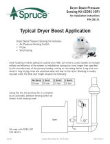
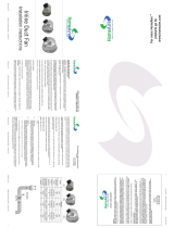
Typical Duct Boost Application
Duct Boost Pressure
Sensing Kit (SDB110P)
for Installation Instructions
P/N 28131
Duct Boost Pressure Sensing Kit includes:
Air Pressure-Sensing Switch
Probe
Vinyl tubing
Duct boosting involves adding an auxiliary fan (RB110) inline to a duct system to increase
airow and efciency of the system in installations having duct runs longer than specied
by the manufacturers of the primary heating, cooling or circulating device. Long duct runs
result in long drying times and excessive wear and tear on the dryer. Boosting is usually
required when the total duct length exceeds the following:
Using this Kit, the auxiliary fan is controlled
by an automatic pressure sensing switch as
shown in the drawing inset.
Kit used with SDB110P
P/N 28131
No Bends 1 Bend 2 Bends 3 Bends
25 feet 20 feet 15 feet 10 feet
Dryer
IN019 Rev G0122 3 Saber Way Ward Hill, MA 01835
Duct Boost Kit (SDB110P)
Installation Instructions
1.0 Auxiliary Fan Location
The auxiliary fan should be mounted with a minimum of 15 feet of ductwork from the
outlet of the primary device to the inlet of the fan.
2.0 Auxiliary Fan Mounting
2.1) Attach the bracket to mounting structure with the 1-inch
screws (2) provided. Insert the grommets (3) supplied into the
slotted holes in the mounting bracket and attach the fan to the
mounting bracket with self-tapping screws (3), provided, avoid
over-tightening the screws.
2.2) Connect the ductwork between the outlet of the device and
the inlet of the fan. Connect the outlet of the fan to the termination ductwork. Seal the
connections with duct tape or similar means.
3.0 Automatic Pressure Switch Installation
The pressure switch must be mounted vertically on a wall
surface as near the outlet of the primary device as possible.
Mount the duct probe through the duct and connect with tub-
ing provided to the pressure switch.
4.0 Electrical Wiring
All wiring must be performed in accordance with the National Fire Protection Associ-
ation’s (NFPA)’’National Electrical Code, Standard #70”-current edition for all com-
mercial and industrial work, and state and local building codes. All wiring must be
performed by a qualied and licensed electrician. Make electrical connections to the
pressure switch and auxiliary fan as shown in the following schematic:
IN019 RevG0122 3 Saber Way Ward Hill, MA 01835
Duct Boost Kit (SDP110P)
Installation Instructions
5.0 Installation Troubleshooting
If the auxillary fan fails to start when the device begins, check the following:
Verify the AC voltage at the pressure switch. The pressure switch-point is
approximately 0.1” WC. The device must generate this positive pressure to close the
switch and start the auxillary fan. If not, check the probe and connecting tubing for
blockage. You may blow gently into the tubing to check the switch operation.
If the auxillary fan cycles on and off after the device cycle begins, check the following:
The auxillary fan may be generating sufcient negative pressure to overcome the
positive pressure generated by the device. This can be veried with a sensitive pressure
measuring device or with an AC voltmeter at the pressure switch. Relocate the
auxillary fan further from the device and recheck.
6.0 Maintenance
Periodic inspection, cleaning and/or inspection of the system lters is required to be
performed every six (6) months or sooner (depending on device) usage to ensure duct
and fan are free of debris.
DISCONNECT ELECTRICAL POWER TO THE UNIT PRIOR TO INSPECTION OR
CLEANING.
NOTE: Excessive noise or vibration from the auxillary device may be an indication of
dirt and/or lint buildup inside the fan impeller.
IN019 Rev G0122 3 Saber Way Ward Hill, MA 01835
IMPORTANT INSTRUCTIONS TO INSTALLER
Inspect the Spruce SDB110P Duct Boost Pressure Sensing Kit for shipping damage within 15 days of receipt. Notify
Spruce of any damages immediately. Spruce is not responsible for damages incurred during shipping. However, for your
benet, Spruce does insure shipments. Install the Spruce SDB110P Duct Boost Pressure Sensing Kit in accordance with
all state and local building codes and state regulations.
Warranty
Subject to any applicable consumer protection legislation, Spruce Environmental Technologies, Inc. (“Spruce”) warrants that the Duct
Boost Pressure Sensing Kit (the “Kit”) will be free from defects in materials and workmanship for a period of one (1) year from the date
of manufacture (the “Warranty Term”).
Warranty claims made during the rst thirty (30) days after installation:
Spruce will replace any Kit which fails due to defects in materials or workmanship. TThe Kit may be returned (at owner’s cost) to either
the point of purchase or the Spruce factory. The point of purchase may require proof of purchase or a bill of sale for replacement.
Warranty claims made after the rst thirty (30) days after nstallation through the end of the Warranty Term:
Spruce will (at its option) either recondition or replace any Kit which fails due to defects in materials or workmanship. The Kit must be
returned (at owner’s cost) to the Spruce factory.
This Warranty is contingent on installation of the Kit in accordance with the instructions provided. This warranty does not apply where
any repairs or alterations have been made or attempted by others, or if the unit has been abused or misused. Warranty does not include
damage in shipment unless the damage is due to the negligence of Spruce.
Spruce is not responsible for installation, removal or delivery costs associated with this Warranty.
LIMITATION OF WARRANTY
EXCEPT AS STATED ABOVE, THE KITS ARE PROVIDED WITHOUT WARRANTY OF ANY KIND, EITHER EXPRESS OR
IMPLIED, INCLUDING, WITHOUT LIMITATION, IMPLIED WARRANTIES OF MERCHANTABILITY AND FITNESS FOR A
PARTICULAR PURPOSE.
IN NO EVENT SHALL SPRUCE BE LIABLE FOR ANY DIRECT, INDIRECT, SPECIAL, INCIDENTAL, OR CONSEQUENTIAL
DAMAGES ARISING OUT OF, OR RELATING TO, THE KIT OR THE PERFORMANCE THEREOF. SPRUCE’S AGGREGATE LIABILITY
HEREUNDER SHALL NOT IN ANY EVENT EXCEED THE AMOUNT OF THE PURCHASE PRICE OF SAID PRODUCT. THE SOLE AND
EXCLUSIVE REMEDY UNDER THIS WARRANTY SHALL BE THE REPAIR OR REPLACEMENT OF THE PRODUCT, TO THE EXTENT
THE SAME DOES NOT MEET WITH SPRUCE’S WARRANTY AS PROVIDED ABOVE.
For service under this Warranty, contact Spruce for a Return Material Authorization (RMA) number and shipping information. No returns
can be accepted without an RMA. If factory return is required, the customer assumes all shipping costs, including insurance, to and from
factory.
Spruce Environmental Technologies, Inc.
3 Saber Way, Ward Hill, MA 01835 USA
TEL (978) 521-3703
FAX (978) 521-3964
Record the following information for your records:
Serial Number: Purchase Date:
/