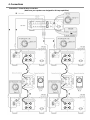
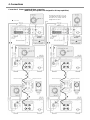
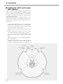
Marantz MA-9S1 is a monaural power amplifier that delivers exceptional audio performance with its advanced features and versatile connectivity options. It boasts a robust design with a die-cast aluminum chassis to minimize vibrations and enhance sound quality. The amplifier offers multiple connection options, including stereo bi-wiring, bi-amp, and complete bi-amp configurations, providing flexibility to connect various speaker systems. The MA-9S1 is equipped with balanced XLR and unbalanced RCA inputs, allowing for seamless integration with a wide range of audio sources.
Marantz MA-9S1 is a monaural power amplifier that delivers exceptional audio performance with its advanced features and versatile connectivity options. It boasts a robust design with a die-cast aluminum chassis to minimize vibrations and enhance sound quality. The amplifier offers multiple connection options, including stereo bi-wiring, bi-amp, and complete bi-amp configurations, providing flexibility to connect various speaker systems. The MA-9S1 is equipped with balanced XLR and unbalanced RCA inputs, allowing for seamless integration with a wide range of audio sources.


-
 1
1
-
 2
2
-
 3
3
-
 4
4
-
 5
5
-
 6
6
-
 7
7
-
 8
8
-
 9
9
-
 10
10
-
 11
11
-
 12
12
-
 13
13
-
 14
14
-
 15
15
-
 16
16
-
 17
17
-
 18
18
-
 19
19
-
 20
20


Marantz MA-9S1 is a monaural power amplifier that delivers exceptional audio performance with its advanced features and versatile connectivity options. It boasts a robust design with a die-cast aluminum chassis to minimize vibrations and enhance sound quality. The amplifier offers multiple connection options, including stereo bi-wiring, bi-amp, and complete bi-amp configurations, providing flexibility to connect various speaker systems. The MA-9S1 is equipped with balanced XLR and unbalanced RCA inputs, allowing for seamless integration with a wide range of audio sources.
Ask a question and I''ll find the answer in the document
Finding information in a document is now easier with AI
Related papers
Other documents
-
Pioneer A-20 User manual
-
First Act MA003 User manual
-
 Audio Pro Evidence E.5 Features
-
Esoteric Esoteric D-03 Supplementary Manual
-
Mackie M2600 User manual
-
Yamaha M-5000 Owner's manual
-
 NHT M6 Owner's Manuals
-
 NHT Evolution System User manual
-
Tektronix 7S11 User manual
-
Monster Cable THX Select SL-STAND 200 User manual


