Page is loading ...

InstallatIon GuIde
XR2500F addRessaBle
FIRe alaRM ContRol Panel

MODEL XR2500F
COMMAND PROCESSOR
INSTALLATION GUIDE
FCC NOTICE
This equipment generates and uses radio frequency energy and, if not installed and used properly in strict accordance
with the manufacturer’s instructions, may cause interference with radio and television reception. It has been type tested
and found to comply with the limits for a Class A computing device in accordance with the specication in Subpart J
of Part 15 of FCC Rules, which are designed to provide reasonable protection against such interference in a residential
installation. If this equipment does cause interference to radio or television reception, which can be determined by
turning the equipment off and on, the installer is encouraged to try to correct the interference by one or more of the
following measures:
Reorient the receiving antenna
Relocate the computer with respect to the receiver
Move the computer away from the receiver
Plug the compute into a different outlet so that computer and receiver are on different branch circuits
If necessary, the installer should consult the dealer or an experienced radio/television technician for additional suggestions.
The installer may nd the following booklet, prepared by the Federal Communications Commission, helpful:
“How to identify and Resolve Radio-TV Interference Problems.”
This booklet is available from the U.S. Government Printing Ofce, Washington D.C. 20402
Stock No. 004-000-00345-4
© 2008 Digital Monitoring Products, Inc.
Information furnished by DMP is believed to be accurate and reliable.
This information is subject to change without notice.

XR2500F Installation Guide Digital Monitoring Products
i
taBle oF Contents
Introduction
1.1 Overview ...................................................................................................... 1
1.2 System Components ...................................................................................... 1
1.3 Power Specications ...................................................................................... 1
1.4 Communication ............................................................................................. 1
1.5 Panel Zones .................................................................................................. 1
1.6 Keypad Bus ................................................................................................... 1
1.7 LX-Bus™ ....................................................................................................... 2
1.8 Outputs ........................................................................................................ 2
1.9 Relays .......................................................................................................... 2
1.10 Zone Reference ............................................................................................. 2
1.11 Compliance Instructions ................................................................................. 2
Mounting
2.1 Mounting the Enclosure .................................................................................. 3
2.2 Surface Mounting .......................................................................................... 3
2.3 Flush Mounting .............................................................................................. 3
2.4 Fire Command Center LCD Keyboard ............................................................... 3
2.5 Metal Backplate ............................................................................................. 3
2.6 Wiring Diagram ............................................................................................. 4
AC Connection
3.1 Transformers and AC Power Connection .......................................................... 5
3.2 16 VAC Transformer ...................................................................................... 5
3.3 Earth Ground (GND) ..................................................................................... 5
Secondary Power Supply
4.1 Description .................................................................................................... 6
4.2 Battery Connection to XR2500F Command Processor panel ............................... 6
Two 866 NAC Modules
5.1 Description .................................................................................................... 7
5.2 Connection .................................................................................................... 7
5.3 Bell Silence/Bell Trouble ................................................................................. 7
LX-Bus™ Operation
6.1 Description .................................................................................................... 8
6.2 XR2500F On-board LX-Bus ............................................................................ 8
6.3 LX-Bus 481 Zone Expansion Interface Card ...................................................... 8
6.4 Installing the 481 Card ................................................................................... 8
893A Dual Phone Line Module
7.1 Description .................................................................................................... 9
7.2 Connection .................................................................................................... 9
7.3 Jumper Settings ............................................................................................ 9
7.4 Digital Dialer ................................................................................................. 9
7.5 Phone Line Monitor ........................................................................................ 9
7.6 Processor Fail Buzzer ..................................................................................... 9
7.7 J10 893A Connector ....................................................................................... 9
7.8 Ground start .................................................................................................. 9
7.9 Notication ..................................................................................................10
7.10 FCC Registration ..........................................................................................10
Fire Command Center
8.1 Description ...................................................................................................11
8.2 Connection ...................................................................................................11
8.3 Remote Fire Command Center .......................................................................11
Expansion
9.1 Zone Expansion ............................................................................................12
9.2 Output Expansion .........................................................................................12

Digital Monitoring Products XR2500F Installation Guide
ii
taBle oF Contents
Accessory Devices
10.1 Wiring Diagram ............................................................................................13
10.2 Lightning Protection ......................................................................................13
10.3 Accessory Devices ........................................................................................14
10.4 Mounting Keypads and Zone Expansion Modules .............................................15
10.5 Connecting LX-Bus and Keypad Bus Devices ...................................................15
Battery Information
11.1 Battery Only Restart .....................................................................................16
11.2 Battery Replacement Period...........................................................................16
11.3 Discharge/Recharge ......................................................................................16
11.4 Battery Supervision .......................................................................................16
11.5 Battery Cutoff ...............................................................................................16
12.6 XR2500F Power Requirements .......................................................................16
11.7 XR2500F Standby Battery Calculations ...........................................................17
11.8 Standby Battery Selection .............................................................................19
Bell Output
12.1 Terminals 5 and 6 .........................................................................................20
Keypad Bus
13.1 Description ...................................................................................................20
13.2 Terminal 7 - RED ..........................................................................................20
13.3 Terminal 8 - YELLOW ....................................................................................20
13.4 Terminal 9 - GREEN ......................................................................................20
13.5 Terminal 10 - BLACK .....................................................................................20
13.6 J8 Programming Connection ..........................................................................20
13.7 OVC LED ......................................................................................................20
Smoke and Glassbreak Detector Output
14.1 Terminals 11 and 12 .....................................................................................21
14.2 Current Rating ..............................................................................................21
Powered Zones for 2-Wire Smoke Detectors
15.1 Terminals 25–26 and 27–28 ..........................................................................21
15.2 Compatible 2-Wire Smoke Detector Chart .......................................................22
Protection Zones
16.1 Terminals 13–24 ...........................................................................................23
16.2 Operational Parameters .................................................................................23
16.3 Zone Response Time .....................................................................................23
16.4 Keyswitch Arming Zone .................................................................................23
Dry Contact Relay Outputs
17.1 Description ...................................................................................................24
17.2 Contact Rating .............................................................................................24
17.3 Output Harness Wiring ..................................................................................24
J11 Annunciator Outputs
18.1 Description ...................................................................................................25
18.2 Model 300 Harness Wiring .............................................................................25
18.3 Model 860 Relay Module ...............................................................................25
J23 6-Pin Header
19.1 Description ...................................................................................................25
J22 LX-Bus Expansion Connector
20.1 Description ...................................................................................................26
20.2 LX-Bus Interface Cards ..................................................................................26
20.3 LX-Bus LEDs .................................................................................................26
20.4. OVC LED ........................................................................................................26
J21 Serial Connector
21.1 Description ...................................................................................................26
21.2 Serial Connector LEDs ...................................................................................26

XR2500F Installation Guide Digital Monitoring Products
iii
taBle oF Contents
J1 Ethernet Connector
22.1 Description ......................................................................................................27
22.2 Ethernet LEDs ..............................................................................................27
Reset and Tamper Headers
23.1 J16 Reset Header ........................................................................................27
23.2 J4 Tamper Header .......................................................................................27
Listed Compliance Specications
24.1 Introduction .................................................................................................28
Universal UL Burglary Specications
25.1 Introduction .................................................................................................28
25.2 Wiring..........................................................................................................28
25.3 Control Outside of Protected Area ..................................................................28
25.4 Police Station Phone Numbers .......................................................................28
25.5 Bypass Reports .............................................................................................28
25.6 System Maintenance .....................................................................................28
25.7 Listed Receivers............................................................................................28
25.8 Power Supply Supervision .............................................................................28
25.9 Wireless Tamper ...........................................................................................28
25.10 Wireless External Contact ..............................................................................28
25.11 Wireless Supervision Time .............................................................................28
25.12 Detect Wireless Jamming ..............................................................................28
Area Information
26.1 Ownership ...................................................................................................29
26.2 Annunciation ................................................................................................29
26.3 Trouble Display .............................................................................................29
26.4 Closing Wait .................................................................................................29
26.5 Local Bell Supervision ...................................................................................29
Household Burglar-Alarm System Units
ANSI/UL 1023
27.1 Audible Devices ............................................................................................29
27.2 Auxiliary Circuits ...........................................................................................29
27.3 Bell Cutoff ....................................................................................................29
27.4 Entry Delay ..................................................................................................29
27.5 Exit Delay ....................................................................................................29
27.6 Weekly Test ..................................................................................................29
27.7 Wireless Audible Annunciation Option ............................................................29
Central-Station and Proprietary Burglar-Alarm Units
ANSI/ UL 1610 AND ANSI/UL 1076
28.1 Opening/Closing Reports ...............................................................................29
28.2 Closing Wait .................................................................................................29
28.3 Entry Delay ..................................................................................................29
28.4 Exit Delay ....................................................................................................29
28.5 Proprietary Dialer .........................................................................................30
28.6 DACT Central Station ....................................................................................30
28.7 Bell Cutoff ....................................................................................................30
28.8 Standard or Encrypted Line Security...............................................................30
28.9 Wireless Audible Annunciation Option ............................................................30
28.10 Model 463G CELL Only, Standard or Encrypted Line Security ...........................30
28.11 Model 463G NET with CELL as Alternate Primary and Dialer Backup,
Standard or Encrypted Line Security .............................................................31
28.12 Model 463G NET with CELL as Backup and Adaptive Primary, Standard
or Encrypted Line Security ............................................................................31

Digital Monitoring Products XR2500F Installation Guide
iv
taBle oF Contents
Holdup Alarm Units
ANSI/UL 636
29.1 ANSI/UL 1610 Required ................................................................................32
29.2 1100X Wireless Receiver ...............................................................................32
29.3 Wireless Supervision Time .............................................................................32
29.4 LED Display ..................................................................................................32
29.5 Jamming Detection .......................................................................................32
29.6 Local Alarm ..................................................................................................32
29.7 Message to Transmit .....................................................................................32
29.8 Wireless Audible Annunciation Option ............................................................32
Digital Burglar Alarm Communicator System Units
ANSI/ UL 1635
30.1 System Trouble Display .................................................................................32
30.2 Digital Dialer Telephone Number ....................................................................32
30.3 Test Time .....................................................................................................32
30.4 Closing Wait .................................................................................................32
Police Station Connected and Local Burglar Alarm Units
ANSI/UL 365
31.1 System Trouble Display .................................................................................32
31.2 Entry Delay ..................................................................................................32
31.3 Exit Delay ....................................................................................................32
31.4 Bell ..............................................................................................................33
31.5 Bell Cutoff ....................................................................................................33
31.6 Automatic Bell Test .......................................................................................33
31.7 Standard or Encrypted Line Security...............................................................33
31.8 Wireless Audible Annunciation Option ............................................................33
31.9 Model 463G CELL Only, Standard or Encrypted Line Security ...........................33
31.10 Model 463G NET with CELL as Alternate Primary and Dialer Backup,
Standard or Encrypted Line Security .............................................................34
31.11 Model 463G NET with CELL as Backup and Adaptive Primary, Standard
or Encrypted Line Security ............................................................................34
Police Station Connected and Local Burglar Alarm Units
ANSI/UL 609
32.1 Mercantile ....................................................................................................35
32.2 Entry Delay ..................................................................................................35
32.3 Exit Delay ....................................................................................................35
32.4 Bell ..............................................................................................................35
32.5 Wireless Audible Annunciation Option ............................................................35
Access Control System Units
ANSI/UL 294
33.1 Panel Designation .........................................................................................35
33.2 Compatible Devices ......................................................................................35
Universal Fire Alarm Specications
34.1 Introduction .................................................................................................36
34.2 Wiring..........................................................................................................36
34.3 Transformer .................................................................................................36
34.4 End-of-Line Resistor ......................................................................................36
34.5 System Trouble Display .................................................................................36
34.6 Fire Display ..................................................................................................36
34.7 Police Station Phone Number .........................................................................36
34.8 System Maintenance .....................................................................................36
34.9 Audible Alarm ...............................................................................................36
34.10 Fire Zone Programming .................................................................................36
34.11 Style D Zones ...............................................................................................36
34.12 Listed Receivers............................................................................................36

XR2500F Installation Guide Digital Monitoring Products
v
taBle oF Contents
Control Units for Fire-Protective Signaling Systems
ANSI/UL 864, NFPA 72
35.1 Power Supply ...............................................................................................37
35.2 Zone Restoral Reports ...................................................................................37
35.3 Power Fail Delay ...........................................................................................37
35.4 Sprinkler Supervisory ....................................................................................37
35.5 DACT Systems ..............................................................................................37
35.7 Local Protective Signaling Systems .................................................................37
35.8 Remote Station Protective Signaling Systems ..................................................37
35.9 Fire Protective Signaling Systems using Internet/Intranet Networks ..................37
35.10 Combination Systems ....................................................................................37
35.11 Remote Annunciators ....................................................................................37
35.12 Notication Appliances .................................................................................38
35.13 Cross Zoning ..................................................................................................38
35.14 Ground Fault ...............................................................................................38
Household Fire Warning System Units
ANSI/UL 985, NFPA 72
36.1 Bell Output Denition ....................................................................................38
36.2 Audible Devices ............................................................................................38
36.3 Auxiliary Circuits ...........................................................................................38
36.4 Bell Cutoff ....................................................................................................38
California State Fire Marshal Specications
37.1 Bell Output Denition ....................................................................................39
New York City (MEA) Specications
38.1 Introduction .................................................................................................39
38.2 Digital Dialer and Network Communication .....................................................39
38.3 Wiring..........................................................................................................39
38.4 Communication Programming ........................................................................39
38.5 Additional Requirements ...............................................................................39
Wiring Diagrams
39.1 Prewired 866 Modules with NAC Extender ......................................................40
39.2 Prewired 866 Class B Style W Modules using Single Notication Appliance ........40
39.3 Prewired 866 Class B Style W Modules with Multiple Notication Appliances ......41
39.4 Prewired 866 Class B Style W Modules with Dual Notication Appliance Circuits 42
39.5 867 Class B Style W using Single Notication Appliance ...................................43
39.6 867 Class B Style W Multiple Notication Appliance Circuit ...............................43
39.7 867 Class B Style W Multiple Notication Appliance Circuits .............................44
39.8 Dual Style D Zone Module Installation ............................................................45
39.9 Remote Station Reversing Relay Connection ...................................................46
39.10 Second LX-Bus™ with Auxiliary Power Supply .................................................47
39.11 LX-Bus™ Module Connection .........................................................................48
39.12 Model 860 Relay Module Connection ..............................................................49
39.13 Powered Burglary Devices ...............................................................................49
Revisions to This Document
OPERATING INSTRUCTIONS MODEL XR2500F PANELS
Mounting Instructions ..............................................................................................52
Listings and Approvals

Digital Monitoring Products XR2500F Installation Guide
vi
This page intentionally left blank

XR2500F Installation Guide Digital Monitoring Products
1
IntRoduCtIon
Introduction
1.1 Overview
The DMP XR2500F Addressable Fire Alarm Control Panel (FACP) is an expandable 24 VDC Fire Alarm Control
with built-in DACT and LCD Fire Command Center keyboard with membrane keyswitch. A complete system
can provide:
• 574programmableinputsandoutputsforcommercialandindustrialrealarmservice.
• Eighton-boardgroundedzones
• Twoon-board12VDCClassB,StyeApoweredzones
Connecta12or24VDCregulated,powerlimitedpowersupplylistedforFireProtectiveSignalingSystems
todistributenoticationappliancepowerbetweenthetwoclassBstyleWNACoutputs.AdditionalNAC
outputs can be added with conventional supervision modules or addressable power supply/boosters.
AddressablesmokedetectorsandinputmodulesroundouttheXR2500Ftodeliveratrulyexibleand
expansiveredetectionandnoticationsystem.TheFireAlarmControlPanelisshippedpre-wiredinared
metalenclosurehousingthenecessarycomponentstomonitorandcontrolrealarmnoticationappliances.
Theenclosuredimensionsareasfollows:32”Hx14.5”Wx4”D.Thelidaddsabout0.5”toeachside.
1.2 System Components
TheXR2500FFACPconsistsofthefollowingpre-wiredcomponents:
• OneModelXR2500FCommandProcessorpanel •OneModel893ADualPhoneLinemodule
• TwoModel866ClassBStyleWNACmodules •OneModel630FPCBandmembraneswitch
• One16VAC,56VAtransformer •TwoModel305Plug-inRelays
• OneModel481ZoneExpansionInterfaceCard •OneMetalBackplate
1.3 Power Specications
TransformerInput: Primaryinput:120VAC,60Hz,Secondaryoutput:16VAC56VA
StandbyBattery: 12VDC,1.0AmpsMax.chargingcurrent
Auxiliary: 12 VDC output at 1.0 Amp Max*
BellOutput: 12VDCat.7AmpMax*
Note:ThecombinedAuxiliaryandBelloutputstotalcannotexceed1.9Ampswitha56VATransformer.
All circuits are inherent Power Limited except the red battery wire and AC terminal.
* For Commercial Fire installations, see the Compliance Instructions section.
1.4 Communication
Built-indialerornetworkcommunicationtoDMPModelSCS-1RReceivers
Built-inContactIDcommunicationtonon-DMPreceivers
893ADualPhoneLineModulewithphonelinesupervision
Can operate as a local panel
1.5 Panel Zones
Eight1kOhmEOLburglaryzones(zones1to8).Connectto869ClassAmoduleforburglaryapplications.
Two3.3kOhmEOLpoweredzonewithreset(zones9and10).
Note:UsethesuppliedDMPModel3111kOhmandDMPModel3013.3kOhmresistors.
1.6 Keypad Bus
Youcanconnectupto15ofthefollowingsupervisedkeypadsandexpansionmodulestothekeypadbus:
• AlphanumericFireCommandCentersorkeypads
• Four-and/orsingle-zoneexpansionmodules
• Single-zonedetectors
• Accesscontrolmodules

Digital Monitoring Products XR2500F Installation Guide
2
IntRoduCtIon
1.7 LX-Bus™
YoucanconnectthefollowingdevicestotheLX-Bus™providedbytheDMP481(supplied)orbythe462N,
481,462P,463G,and472InterfaceCardsuptothemaximumnumberofLX-Bus™addresses.SeeAccessory
Devices.
• Model521LXor521LXTSmokeDetectorswithCleanMe
• Sixteen-,eight-,four-and/orsingle-zoneexpansionmodules
• Single-zonedetectors
• Relayoutputexpansionmodules
• Graphicannunciatormodules
1.8 Outputs
TheXR2500Fprovidestwopre-installedModel305SinglePole,DoubleThrow(SPDT)relayoutputs,each
rated1Ampat30VDC(powerlimitedsourcesonly).
TheXR2500Falsoprovidesfourprogrammableopencollectoroutputsratedfor30VDC@50mAeach.The
opencollectoroutputsprovidegroundconnectionforapositivevoltagesource.AModel300OutputHarness
isrequiredtousetheseoutputsandmaybeconnectedtoaModel860RelayOutputModule.
1.9 Relays
TheXR2500FshipswithtwoModel305Relayspre-installedtoallowzonealarmcontrolforthe866NAC
Modules.Whenarealarmoccursthebelloutputisfactoryprogrammedtoturnonandprovidepowerto
thecontactsoftherelays.Speciczoneprogrammingdetermineswhetheroneorbothrelaysturnonsignal
voltagetothe866NACs.ThisallowscontroloftheNACsbyzone.
1.10 Zone Reference
TheXR2500Fhasbeenpre-wiredinthefactory.Therst866NACmoduleconnectstoZone1.Thesecond
866NACmoduleconnectstoZone2.
1.11 Compliance Instructions
ForapplicationsthatmustconformtoalocalauthoritiesinstallationstandardoraNationalRecognizedTesting
Laboratorycerticatedsystem,pleaseseetheWiringDiagramsforNoticationAppliancesandtheListed
ComplianceSpecicationssectionneartheendofthisguideforadditionalinstructions.

XR2500F Installation Guide Digital Monitoring Products
3
IntRoduCtIon
Mounting
2.1 Mounting the Enclosure
TheXR2500Fmustbemountedinasecure,
drylocationtoprotecttheunitfromdamage
duetotamperingandtheelements.The
enclosurecanbeeitherushmountedor
surfacemountedandincludesahingeddoor
with lock. The hole in the enclosure door
allows access to the Fire Command Center
withoutopeningthedoor.Figure1illustrates
themountingholelocationsforthepanel
enclosure.
Theenclosuredimensionsare32”tall,14.5”
wide,by4”deep.Thelidaddsabout0.5”to
each side.
2.2 Surface Mounting
The enclosure center hole should be attached
toawallstud.Duetotheenclosureweight,
especiallythebatteries,itisextremely
important to mount the enclosure on the
stud. Attach the two holes beside the center
holetosheetrocktosecureenclosure.When
mountingtheenclosure,besuretoleave
roomforthepaneldoortoswingopen.The
door lock should be easily accessible.
2.3 Flush Mounting
Theenclosurecanalsobeushmounted.Use
1”screwstosecuretheenclosurebetween
twostudsusingthetwosetsofholeson
thesidesoftheenclosure.Usethetopand
bottomholestosecuretohorizontalstuds,if
necessary.
2.4 Fire Command Center LCD
Keyboard
A Fire Command Center LCD Keyboard
hasbeenfactoryinstalledontheXR2500F
enclosure. A keyswitch has also been
installedandpre-wiredtotheleftofthe
keyboard. The user can turn the keyswitch to
enablethefourfunctionkeyswithoutopening
the enclosure door.
2.5 Metal Backplate
The XR2500F components are pre-wired
and installed on a metal backplate. The
backplatecanbeeasilyremovedtokeepcomponentssafeduringpre-wireactivities.
Remove AC and battery power from the XR2500F panel before removing the backplate. Disconnect all
battery,transformer,andtheFireCommandCenterLCDkeyboardwires.Fromthepanel,disconnecttheAC
wiresfromterminals1and2.Disconnectthebatterywireseitherfromthebatteriesorthepanelterminals
3and4.Finally,disconnectthekeyboardwiresfrompanelterminals7,8,9,and10.
Removethescrewssecuringthebackplatetotheenclosure.Loosenthetwotopscrewsthatthebackplate
hangson.Afterlooseningandremovingthescrews,liftthebackplateupslightlyandpullthebackplate
towardyou.Whenreinstallingthebackplate,besureallconnectionsaresecure.
Figure2illustratesthebackplateandthecomponents.Thebackplateisshowninlightgray.
3/4" X 1/2" Knockouts
Hole for Flush
Mounting
Holes for Surface Mounting
Holes for 1" screws for
Flush Mounting
Battery Shelf
Hole for Flush Mounting
Additional Holes for Surface Mounting
Figure 1: Mounting the XR2500F Enclosure

Digital Monitoring Products XR2500F Installation Guide
4
IntRoduCtIon
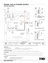
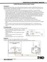
2.6 Wiring Diagram
TheXR2500Fsystembelowshowsthecomponentlayout.Thewiresshowninthisguidehavebeenfactory
installedandconnected.Thedashedlinesrepresentwiresrunningunderneathorbehindacomponent.
Detailedwiringdiagramsforeachsuppliedcomponentappearinfollowingsectionsofthisguide.
AC
12345 678 10 11 12 13 14 15 16 17 18 199202122232425262728
+B BELL GND SMK GNDRED YEL GRN BLK Z1 Z2 Z3 Z4 Z5 Z6 Z7 Z8 Z9+ Z9– Z10+ Z10–AC –B GND GND GNDGND
Output 1Output 2
J3
Phone
Line
J22
Battery
Start
Power
LED
J8
PROG
J4
Tamper
J16
Reset
Out1 Out2
Outputs 3-6
3
4
5
J1
Ethernet
R
L
X
Link LED
Power LED
OVC
XR2500F
Command
Processor™
Panel
J6 Expansion
Card Slot
TYPES OF SERVICE
Suitable for Mercantile Local
and Police Station Connect.
Suitable for Proprietary, PPU,
other technologies, local.
Suitable for Signaling and
Remote Station PPU DACT
Service.
Suitable for manual fire alarm,
automatic fire alarm, sprinkler
supervisory, or water flow
alarm.
Suitable for Standard or
Encrypted Central Station with
NET or CELL communication.
Suitable for Household Fire and
Household Burglary.
Suitable for Coded and March
Time signaling.
NFPA 72
This equipment should be
installed in accordance with
the National Fire Alarm Code,
ANSI/NFPA 72 (National Fire
Protection Association,
Batterymarch Park, Quincy, MA
02269). Printed information
describing proper installation,
operation, testing,
maintenance, evacuation
planning, and repair service is
to be provided with this
equipment.
Zones 9, 10, and all expanded
zones are suitable for Class B
(as applicable for the initiating
and signaling line circuits per
ANSI/UL 864 Table 48.2 or
48.3). Installation limits under
local Authority Having
Jurisdiction (AHJ).
Control Unit
Delay
Smoke
Model
Detector
Delay
Verification
Zones
WARNING
THIS UNIT MAY BE PROGRAMMED TO USE AN ALARM VERIFICATION FEATURE THAT RESULTS IN DELAY OF THE
SYSTEM ALARM SIGNAL FROM THE INDICATED CIRCUITS. THE TOTAL DELAY (CONTROL UNIT PLUS SMOKE
DETECTORS) SHALL NOT EXCEED 60 SECONDS. NO OTHER SMOKE DETECTOR SHALL BE CONNECTED TO THESE
CIRCUITS UNLESS APPROVED BY THE LOCAL AUTHORITY HAVING JURISDICTION (AHJ).
See LT- 0759, 893A
Dual Phone Line
Module section
for complete 893A
information.
Refer to LT-0759, Standby
Battery Selection section
for battery standby times and
numbers of batteries to use.
See LT- 0759, Two 866
NAC Modules section for
complete 866 information.
866
Module
866
Module
+-+
-
12 VDC battery
Two 12 VDC batteries
connected in parallel with a
Model 318 Dual Battery
Harness. See Secondary
Power Supply section.
XR2500F Secondary Power Supply
1 Amp maximum charge current.
Use only 12 VDC rechargeable batteries.
Replace every 3 to 5 years.
12 VDC battery
Black
Red
To Fire Command Center on enclosure door
From XR2500F
panel to 12 VDC.
56 VA
Transformer
GROUND
GREEN
GREEN/
YELLOW
WHITE
BLACK
WHITE
BLACK
To Telco
S
To Notification
Appliances
S
S
S
S
S
S
S
S
Battery Compartment
10K EOL
10K EOL
16 VAC
Expansion Zones
Connected to
Enclosure Door
Use Marking
Commercial and Residential
Fire, Burglar, Holdup, and
Access Protected Premise Unit
Figure 2: XR2500F System

XR2500F Installation Guide Digital Monitoring Products
5
IntRoduCtIon
AC Connection
3.1 Transformers and AC Power Connection
The AC connection should be completed by a licensed electrician.
Never share the Fire Alarm Control Panel circuit with any other equipment.
TheXR2500Fcomessuppliedwitha16VAC56VAtransformer.The16VACtransformerwhiteleadsandblack
leadsmustbeconnectedtoanunswitched120VAC60Hzpowersourcewithatleast.87Aavailable.Observe
wirecolorsandconnectthetransformerwires:
TheBlacktransformerwirestotheBlack120VACwire
TheWhitetransformerwirestotheWhite120VACwire
TheGreen/Yellowgroundwiretotheelectricalground
S
56 VA
Transformer
To XR2500F Panel
Violet
Terminal 1
Gray
Terminal 2
16 VAC
56 VA
Transformer
L-Bracket
Bracket
Nut
Bracket
Nut
GROUND
GREEN
GREEN/
YELLOW
WHITE
BLACK
WHITE
BLACK
S
S
Connected to
Enclosure Door
Figure 3: Transformers and AC Power Connection
Always ground the panel before applying power to any devices! Use18AWGorlargerforallpower
connections.TheXR2500Fmustbeproperlygroundedbeforeconnectinganydevicesorapplyingpower
tothepanel.PropergroundingprotectsagainstElectrostaticDischarge(ESD)thatcandamagesystem
components.
3.2 16 VAC Transformer
The16VAC56VAtransformersuppliespowertotheXR2500Fpanelandisfactorypre-wired.SeeFigure3:
TransformersandACPowerConnection.AlsorefertoFigure11:XR2500FPanelWiringDiagram.
3.3 Earth Ground (GND)
TheXR2500Fterminal4mustbeconnectedtoearthgroundusing14AWGorlargerwiretoprovideproper
transientsuppression.DMPrecommendsconnectingtoacoldwaterpipe,buildingground,orgroundrod
only.Donotconnecttoanelectricalgroundorconduit,sprinklerorgaspipes,ortoatelephonecompany
ground.

Digital Monitoring Products XR2500F Installation Guide
6
IntRoduCtIon
Secondary Power Supply
4.1 Description
TheXR2500Fsystemincludespre-wiredcablesforconnecting12VDCbatterytotheXR2500Fpanel.Observe
polaritywhenconnectingallbatteries.
Use sealed lead-acid batteries only.UsetheDMPModel367,368,369,365,366,12VDCsealedlead-acid
rechargeablebatteries.BatteriessuppliedbyDMPhavebeentestedtoensureproperchargingwithDMP
products.
GelcellbatteriescannotbeusedwiththeXR2500Fpanel.
4.2 Battery Connection to XR2500F Command Processor panel
For12VDCbatteryoperationtotheXR2500F,connecttheblackbatteryleadtothebatterynegative
terminal. The black battery wire connects to XR2500F panel terminal 4.
Connect the red battery lead to the battery positive terminal. The red battery wire connects to XR2500F
panelterminal3.SeeFigure11andFigure2.
AddasecondbatteryinparallelusingtheDMPModel318DualBatteryHarness.Whenwiringtwobatteries
withtheModel318DualBatteryHarness,plugtheDualBatteryHarnessredmaleendintothepanelred
femalebatterylead.PlugtheDualBatteryHarnessblackmaleendintothepanelblackfemalebattery
lead.AttachbothDualWiringHarnessfemaleleadstothetwobatteriesasdescribedabove.SeeTable3:
BatteryCalculations.

XR2500F Installation Guide Digital Monitoring Products
7
IntRoduCtIon
Two 866 NAC Modules
5.1 Description
Each866providesonestyleWindicatingcircuitforsupervisinglistedpolarizednoticationappliances,
suchasbells,strobes,andhorns.SeeTable1:NoticationAppliancesforalistofapprovednotication
appliances.
5.2 Connection
Each866moduleispre-installedontheremovablebackplateusingthestandardthree-holeconguration.
Themodulesarefactorypre-wiredtoeachotherandtheXR2500Fpanel.Refertothegurebelowandto
Figure2:XR2500FSystemforwiringconnections.
Connecta12or24VDCregulated,powerlimitedpowersupplylistedforFireProtectiveSignalingSystemsto
terminals2and4ofeachmoduletoprovideNoticationappliancepower.Connectnoticationappliances
toterminals5and6ofeachmodule.Eachmoduleprovidesazoneofnoticationandcanbeactivated
separately.
1 AUX PWR
2 GND
3 Alarm In
4 Bell PWR In
5 Bell Out +
6 Bell Out -
7 Bell Trouble
8 Bell Trouble
866
Module #1
Normal/Silence Switch
1 AUX PWR
2 GND
3 Alarm In
4 Bell PWR In
5 Bell Out +
6 Bell Out -
7 Bell Trouble
8 Bell Trouble
866
Module #2
Normal/Silence Switch
To XR2500F Output #1 (J2 pin #2)
To XR2500F terminal 13 (Zone 1)
To XR2500F terminal 7
To 24 VDC Power Supply DC -
To XR2500F Output #2 (J2 pin #5)
To 24 VDC Power Supply DC +
To XR2500F terminal 15 (Zone 2)
To 24 VDC Power Supply
Listed, Polarized
Notification Appliances
See the Notification
Appliance section
Listed, Polarized
Notification Appliances
See the Notification
Appliance section
Pre-installed 1K EOL
Pre-installed 1K EOL
Figure 5: 866 Modules Wiring
5.3 Bell Silence/Bell Trouble
Abellsilenceswitchonthe866moduleisprovidedtopreventindicatingdevicesfromsoundingduring
systemtesting.WhentheSilencepositionisselected,a15-seconddelayoccursbeforethe866belltrouble
contacts(terminals7and8)open.SelecttheNormalpositionaftertestingtoreturnthe866moduleto
normal operation.

Digital Monitoring Products XR2500F Installation Guide
8
IntRoduCtIon
LX-Bus™ Operation
6.1 Description
TheXR2500FCommandProcessor™panelsupportsLX-Busoperationdirectlyfromthepanel.EachLX-Bus
circuitprovides100additionalzones.UseJ22LX-BusHeaderfortherst100zones.Usetheinstalled481
ZoneExpansionInterfaceCardforthenext100zones.Thisprovidesatotalof200expansionzones.To
installuptofouradditionalInterfaceCardsuseaModel461InterfaceAdaptorCard.
6.2 XR2500F On-board LX-Bus
ToenableJ22tooperateasanLX-Bus,placeajumperonthetwopinsnexttotheletter“L”ontheJ23
6-Pinheader.WhenusingJ22asanLX-Bus,connectaDMPModel3004-wireHarnesstotheJ224-pin
headerlabeledLX-BUS.Thisprovidestherst100LX-Buszonesnumbered500-599.Respectwirecolors
whenconnectingdevicesanduseallfourwires.ResetthepanelusingtheJ16jumpertoactivateLX-Bus
operation.SeeConnectingLX-BusandKeypadDevicessectionformaximumwiringdistances.
Note:DoNOTuseshieldedwirewhenusingtheLX-Bus.DoNOTconnectthewiresfromthe4-wireharness
to the panel terminals.
6.3 LX-Bus 481 Zone Expansion Interface Card
The481ZoneExpansionInterfaceCardprovidesanadditional100zonestotheXR2500F.Whenusedin
conjunctionwiththeon-boardJ22LX-Busthe481LX-Buszonesarenumbered600to699.
6.4 Installing the 481 Card
Remove AC and battery power from the XR2500F panel and ground yourself before handling and
installing the 481 Card.
1.Alignthe481Card50pinconnectorwiththeXR2500FpanelJ6connector.
2.Pressthe481ontotheJ6connectorwhileapplyingevenpressuretobothsides.
B
J6 Interface Card
Connector
18
19
20
21
22 23
24
25
26 27
28
Z5
Z6
Z7
Z8 Z9+
Z9-
Z10+
Z10-
GND
GND
481 Zone
Expansion
Interface
Card
Red—Auxiliary Power
Yellow—Data In
Green—Data Out
Black—Ground
Zone Expansion
Harness Connectors
To LX-Bus Modules
Command Processor
Panel
Figure 6: 481 Wiring

XR2500F Installation Guide Digital Monitoring Products
9
IntRoduCtIon
893A Dual Phone Line Module
7.1 Description
The893Aisadualtelephonelinesupervisionmodulethatallowsthepaneltoindicateaphonelinefailure
tothepremisesandthecentralmonitoringstation.Afterthe893Asensesafailureonthemainline,it
switchestothebackup,orsecondary,phoneline.The893Ainstallsontheremovablebackplateabovethe
XR2500F circuit board.
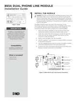
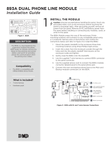
7.2 Connection
Thepre-wired893AconnectsthepaneltothepublictelephonenetworkthroughaninstalledDMP356RJ
CablebetweentheXR2500FpanelJ3connectorandthe893AModuleJ3connectorlabeledPANEL.
J2
DD
MPX
J1
DD
MPX
J3
PANEL
J4
MAIN
J5
BACKUP
P10
Factory pre-wired
to XR2500F panel
Phone Jack
Connector, J3
To Primary
telephone line
To Secondary telephone line
Communication Jumpers:
Both Set both Jumpers
Processor
Stopped Buzzer
Factory pre-wired
to XR2500F panel
J10 Connector
893A Dual Telephone Line Module
Figure 8: 893A Dual Phone Line Module Wiring
7.3 Jumper Settings
The893Amodulehastwosetsofjumpers.BothcommunicationjumpersmustbesetforDD(digitaldialer)
operation.Donotsetthe893AjumpersnexttoMPX.The893AModulesupportsmultiplexoperation,but
the XR2500F panel does not.
7.4 Digital Dialer
Youcancongurethe893Atoprovidetwolinesofdigitaldialer.Maximumlineimpedanceis100Ohms.The
XR2500FispresetatthefactoryforDigitalDialer.TheMainmodularjack(J4)isusedfortheprimarydigital
dialerline.TheBackupmodularjack(J5)isusedforthesecondarydigitaldialerline.
7.5 Phone Line Monitor
The893Ausesaphonelinemonitorforthemainandbackupphonelines.Whensendingareport,the893A
veriesthemainphonelineisworkingbeforesendingdata.Ifthelineisbad,themoduleteststhebackup
phoneline.The893Asendsthereportontherstworkingphoneline.
The phone line monitor has a two-minute trouble delay and a one-minute restore delay. Phone line trouble
isdisplayedintheFireCommandCenterLCDStatusListasaSystemTrouble.TheFireCommandCenter
LCDisfactoryprogrammedtodisplaysystemtroublesintheStatusList.
7.6 Processor Fail Buzzer
The893AmodulealsomonitorsthepanelCPUandsoundsatroublebuzzerwhenevereitherthepanel
processorisresetusingJ16ortheprocessorstopsfunctioning.
7.7 J10 893A Connector
The893ADualPhoneLineModuleconnectstotheXR2500FJ10.Refertothe893AInstallationSheet
(LT-0135)forcompleteinformation.
7.8 Ground start
Ground start phone service cannot be used on commercial or residential re applications.

Digital Monitoring Products XR2500F Installation Guide
10
IntRoduCtIon
7.9 Notication
Theusermustnotrepairregisteredterminalequipment.Incaseoftrouble,immediatelyunplugthedevice
fromthetelephonejack.Thefactorywarrantyprovidesforrepairs.Registeredterminalequipmentmay
notbeusedonpartylinesorinconnectionwithcointelephones.Notifythetelephonecompanywiththe
followinginformation:
a. The particular line(s) where the service is connected
b.TheFCCregistrationnumber
c.Theringerequivalence
d.Thedevicemake,model,andserialnumber(seetheserial#stickeronthepanel)
7.10 FCC Registration
TheModelXR2500FcomplieswithPart68oftheFCCrulesandtherequirementsadoptedbytheACTA.On
theoutsideoftheenclosureofthisequipmentisalabelthatcontains,amongotherinformation,aproduct
identierintheformatUS:CCKAL00BXR500.Ifrequestedthisnumbermustbeprovidedtothetelephone
company.
Aplugandjackusedtoconnectthisequipmenttothepremiseswiringandtelephonenetworkmustcomply
withtheapplicableFCCPart68rulesandrequirementsadoptedbytheACTA.Seeinstallationinstructions
fordetails.
TheRingerEquivalenceNumber(REN)isusedtodeterminethenumberofdevicesthatmaybeconnected
toatelephoneline.ExcessiveRENsonatelephonelinemayresultinthedevicesnotringinginresponseto
anincomingcall.Inmostbutnotallareas,thesumofRENsshouldnotexceedve(5.0).Tobecertainof
thenumberofdevicesthatmaybeconnectedtoaline,asdeterminedbythetotalRENs,contactthelocal
telephone company.
IftheXR2500Fcausesharmtothetelephonenetwork,thetelephonecompanywillnotifyyouinadvance
thattemporarydiscontinuanceofservicemayberequired.Butifadvancenoticeisn’tpractical,the
telephonecompanywillnotifythecustomerassoonaspossible.Also,youwillbeadvisedofyourrightto
leacomplaintwiththeFCCifyoubelieveitisnecessary.
Thetelephonecompanymaymakechangesinitsfacilities,equipment,operationsorproceduresthatcould
affecttheoperationoftheequipment.Ifthishappensthetelephonecompanywillprovideadvancenotice
inorderforyoutomakenecessarymodicationstomaintainuninterruptedservice.
IftroubleisexperiencedwiththeModelXR2500F,forrepairorwarrantyinformation,pleasecontactDMPat
theaddressandtelephonenumberlistedonthebackofthisdocument.Iftheequipmentiscausingharmto
thetelephonenetwork,thetelephonecompanymayrequestthatyoudisconnecttheequipmentuntilthe
problem is resolved.
Ifyourpremiseshasspeciallywiredalarmequipmentconnectedtothetelephoneline,ensurethe
installationoftheXR2500Fdoesnotdisableyouralarmequipment.Ifyouhavequestionsaboutwhatwill
disablealarmequipment,consultyourtelephonecompanyoraqualiedinstaller.
Caution:Toensureproperoperation,thisequipmentmustbeinstalledaccordingtotheinstallation
instructionsinthismanual.Toverifythattheequipmentisoperatingproperlyandcansuccessfullyreportan
alarm,thisequipmentmustbetestedimmediatelyafterinstallation,andperiodicallythereafter,according
tothetestinstructionsinthisdocumentandtheXR500SeriesProgrammingGuide(LT-0679).Additionally,
vericationofLineSeizecapabilityshouldbemadeimmediatelyafterinstallation,andperiodically
thereafter,inordertoensurethatthisequipmentcaninitiateacallevenwhenotherequipment(telephone,
answeringsystem,computermodem,etc.)connectedtothesamelineisinuse.

XR2500F Installation Guide Digital Monitoring Products
11
IntRoduCtIon
Fire Command Center
8.1 Description
TheXR2500FprovidesanLCDdisplayand20-keykeyboardforprogrammingandsystemuseroperation.The
Fire Command Center is installed on the XR2500F enclosure door. A keyswitch is installed and pre-wired
totheleftofthekeyboard.Theusermustturnthekeyswitchtoenablethefourfunctionkeys.Seethe
illustration below.
POWER
TROUBLE
ALARM
COMMAND
1234
5678
90
ABC DEF GHI JKL
MNOPQR STU VWX
YX
ENABLE
SILENCE
RESET
TEST
DRILL
Fire Command Center
Figure 10: Fire Command Center LCD and Keyboard
8.2 Connection
Thedisplayandkeyboardarefactorypre-wiredtotheXR2500Fpanelterminals7,8,9,and10.Forstandby
batterycalculations,thedisplaydraws92mAofcurrentinnormalstandbyoralarmcondition.SeePanel
StandbyBatteryCalculations.Thekeyswitchispre-wiredtothemembranekeyboard.
8.3 Remote Fire Command Center
UptofteenModel630FRemoteFireCommandCentersmayberemotelyattachedtotheXR2500Fsystem.
Seethe630FInstallationGuide(LT-0741)foradditionalinformation.

Digital Monitoring Products XR2500F Installation Guide
12
IntRoduCtIon
Expansion
9.1 Zone Expansion
Upto574reandburglaryzonesareavailableontheXR2500FusingDMPSecurityCommandkeypadremote
zonecapabilityandzoneexpansionmodules.Thepanelkeypaddatabussupportsuptosixteensupervised
deviceaddresseswitheachaddresssupportinguptofourprogrammableexpansionzones.
Upto500zonesareavailableusingtheon-boardLX-Busalongwithadditionalexpansionmodules.Usethe
461InterfaceAdaptor,462N,462P,463G,or481interfacecards,andanycombinationofsixteen,eight,four,
andsinglepointzoneexpandermodulesandsinglepointLX-Busdetectors.
Combinedcurrentrequirementsofadditionalmodulesmayrequireanadditionalpowersupply.Seethe
710/710FBusSplitter/RepeaterInstallationGuide(LT-0310).RefertotheStandbyBatteryCalculations
sectionwhencalculatingpowerrequirements.
Note:DonotuseshieldedwireforLX-BusorKeypadBuscircuits.
9.2 Output Expansion
Note:DonotuseshieldedwireforLX-BusorKeypadBuscircuits.
InadditiontothetwoSPDTrelaysandfourprogrammableopencollectoroutputsontheXR2500F,youcan
alsoconnectupto25programmableModel716OutputExpansionModulestoeachLX-Bus.Thesemodules
canprovideanadditional500programmableSPDTrelays.
TheXR2500Fprovides100OutputSchedulesyoucanuseforprogrammingthe716toperformavarietyof
annunciationandcontrolfunctions.Youcanalsoassignthe716outputstoanypanelOutputOptionssuchas
FireAlarm,CommunicationFail,orPhoneTroubleOutputs.Refertothe716InstallationGuide(LT-0183).
TheLX-Bus™alsosupportstheModel717GraphicAnnunciatorModule.Each717modulesupplies20
switchedgroundoutputsthatfollowthestateoftheirassignedzones.
Note:The717supportsthersteightkeypadbuszones.TofollowKeypadBuszonesninethrough16,install
multiple716modules.Refertothe717InstallationGuide(LT-0235)and716InstallationGuide(LT-0183).
/