Page is loading ...

USER'S GUIDE
Vaisala DRYCAP® Hand-Held
Dewpoint Mete
r
DM70
M010091EN-F

PUBLISHED BY
Vaisala Oyj Phone (int.): +358 9 8949 1
P.O. Box 26 Fax: +358 9 8949 2227
FIN-00421 Helsinki
Finland
Visit our Internet pages at http://www.vaisala.com/
© Vaisala 2007
No part of this manual may be reproduced in any form or by any means, electronic or
mechanical (including photocopying), nor may its contents be communicated to a third
party without prior written permission of the copyright holder.
The contents are subject to change without prior notice.
Please observe that this manual does not create any legally binding obligations for
Vaisala towards the customer or end user. All legally binding commitments and
agreements are included exclusively in the applicable supply contract or Conditions of
Sale.

________________________________________________________________________________
Table of Contents
CHAPTER 1
GENERAL INFORMATION............................................................................6
Safety.........................................................................................6
General Safety Considerations.............................................6
Feedback...................................................................................6
Recycling ..................................................................................7
Trademarks...............................................................................7
Warranty....................................................................................8
CHAPTER 2
PRODUCT OVERVIEW..................................................................................9
Introduction to Vaisala DRYCAP
®
Hand-Held Dewpoint
Meter DM70 ...............................................................................9
Basic Features and Options................................................10
Parts Description.................................................................11
CHAPTER 3
PREPARATIONS BEFORE USE.................................................................13
Installing and Removing the Battery Pack ..........................13
Charging the Battery Pack ....................................................14
Buttons and Navigation.........................................................15
Turning on the Device............................................................15
CHAPTER 4
DEWPOINT MEASUREMENT.....................................................................17
Measuring ...............................................................................17
CHAPTER 5
USER INTERFACE ......................................................................................19
Basic Display..........................................................................19
Menus......................................................................................20
Display Menu..........................................................................21
Quantities and Units............................................................21
Rounding.............................................................................22
Hold/Save............................................................................23
Graphic History ...................................................................23
Functions Menu......................................................................24
Alarm...................................................................................24
Analog Output .....................................................................26
Selecting and Scaling the Analog Output ......................26
VAISALA________________________________________________________________________ 1

USER'S GUIDE____________________________________________________________________
Auto-Calibration...................................................................27
Automatic Auto-Calibration.............................................27
Turning off Automatic Auto-Calibration..........................28
Manual Auto-Calibration.................................................28
Sensor Purge.......................................................................29
Turning on/off Automatic Sensor Purge.........................30
Changing Automatic Sensor Purge Interval...................30
Manual Sensor Purge.....................................................31
Calibrate Transmitters (used only with DMP248)................32
Recording/Viewing Menu.......................................................32
Recording Data....................................................................32
Stopping Recording........................................................34
View Recorded Data ...........................................................34
Memory Status ....................................................................34
Clear Data Memory .............................................................35
Transferring Recorded Data to PC......................................35
Environment Menu .................................................................36
Pressure Settings................................................................36
Settings Menu.........................................................................37
User Interface......................................................................37
Language .......................................................................37
Automatic Power Off ......................................................38
Program Shortcut Keys..................................................38
Button Tones and Backlight ...........................................39
Date and Time.....................................................................39
Measurement Settings ........................................................40
Automatic Auto-Calibration.............................................40
Automatic Purge.............................................................40
Molecular Weight............................................................40
Purge Interval.................................................................41
Device Information...............................................................41
Factory Settings...................................................................42
CHAPTER 6
FIELD CALIBRATION CHECK OF FIXED TRANSMITTERS.....................43
Field Calibration Check of DMT340/DMT242/DMT142 ........43
Field Calibration Check of DMP248......................................44
CHAPTER 7
SAMPLING FROM PROCESSES................................................................47
Sampling Cells........................................................................48
DSC74.................................................................................48
DSC74B...............................................................................49
DSC74C ..............................................................................49
DMT242SC..........................................................................52
DMT242SC2........................................................................52
Connection to Pressurized Processes Using the DSC74
Sampling Cell..........................................................................52
DSS70A Sampling System.....................................................54
DSS70A Sampling Procedure.............................................55
DSS70A Maintenance.........................................................56
Recharging the Battery...................................................56
2 ___________________________________________________________________ M010091EN-F

________________________________________________________________________________
Changing the Battery .....................................................57
Changing the Filter.........................................................59
Changing the Fuses.......................................................60
CHAPTER 8
MEASURING MOISTURE IN SF
6
GAS-INSULATED EQUIPMENT...........61
Overview .................................................................................61
Operating Environment.......................................................62
Measuring............................................................................62
CHAPTER 9
CALIBRATION, ADJUSTMENT, AND MAINTENANCE.............................65
Calibration...............................................................................65
User Calibration and Adjustment........................................65
Adjusting DM70..............................................................66
Adjusting DMT340 Series Transmitters Using DM70 as
Reference or Terminal...................................................66
Adjusting Dewpoint................................................................67
Two-Point Relative Humidity Adjustment............................67
Two-Point Relative Humidity Adjustment of DMT340
Series Transmitters Using DM70...................................68
Adjusting Dewpoint T
d/f
........................................................70
T
d/f
Adjustment of DM70.................................................70
T
d/f
Adjustment of DMT340 Series Transmitters using
DM70..............................................................................71
To Same as T
d/f I/II
......................................................72
1-Point Adjustment....................................................73
Adjusting Temperature..........................................................74
Temperature Adjustment of DM70......................................74
One-Point Adjustment....................................................74
Two-Point Adjustment....................................................75
Temperature Adjustment of DMT340 Series Using DM70 .75
To Same as T
I/II
..............................................................76
1-Point Adjustment.........................................................76
2-Point Adjustment.........................................................77
Vaisala Service Centers.........................................................78
CHAPTER 10
DE-COMMISSIONING, DISMANTLING, AND DISPOSAL.........................79
CHAPTER 11
TECHNICAL SPECIFICATIONS..................................................................81
Measured Variables................................................................81
Dewpoint Temperature........................................................81
Temperature...................................................................83
PPM (ppm
v
or ppm
w
)......................................................83
Absolute Humidity (DMP74A Probe Recommended)....84
Mixing Ratio (DMP74A Probe Recommended).............84
Relative Humidity (DMP74A).........................................84
Measurement Environment............................................84
Probe General................................................................85
VAISALA________________________________________________________________________ 3

USER'S GUIDE____________________________________________________________________
MI70 Indicator......................................................................85
Indicator General............................................................85
Battery Pack...................................................................86
DMP74 Probe + MI70 Indicator = Vaisala DRYCAP
®
DM70
Hand-Held Dewpoint Meter.................................................86
General...........................................................................86
Electromagnetic Compatibility........................................87
Sampling Cells ...............................................................87
DMT242SC Sampling Cell........................................87
DMT242SC2 Sampling Cell with Swagelok
Connectors................................................................87
DSC74 Sampling Cell for Pressurized Gases...........87
DSC74B Two-Pressure Sampling Cell .....................87
DSC74C....................................................................88
DMCOIL ....................................................................88
DSS70A Sampling System.............................................88
Accessories.........................................................................89
Dimensions..........................................................................90
List of Figures
Figure 1 Hand-Held Dewpoint Meter DM70............................................11
Figure 2 Installing the Battery Pack........................................................13
Figure 3 Buttons......................................................................................15
Figure 4 Basic Display............................................................................19
Figure 5 Menus.......................................................................................21
Figure 6 Quantities and Units Menu.......................................................22
Figure 7 Alarm ........................................................................................24
Figure 8 Analog Output...........................................................................26
Figure 9 Auto-Calibration Displays.........................................................29
Figure 10 Sensor Purge Displays.............................................................31
Figure 11 Calibrate Transmitters Display .................................................32
Figure 12 Recording .................................................................................32
Figure 13 Environment Menu ...................................................................36
Figure 14 User Interface...........................................................................37
Figure 15 Hold/Save Replaced by Auto Cal.............................................39
Figure 16 Measurement Settings Menu....................................................40
Figure 17 Device Information....................................................................41
Figure 18 Indicator and Probe Information...............................................42
Figure 19 Calibrate Transmitters Message...............................................45
Figure 20 DSC74 Sampling Cell with the Adapters..................................48
Figure 21 DSC74B....................................................................................49
Figure 22 Default Assembly of DSC74C ..................................................50
Figure 23 Alternative Assembly of DSC74C for Tight Spaces .................51
Figure 24 DMT242SC and DMT242SC2 Sampling Cells.........................52
Figure 25 DM70 with the Case .................................................................55
Figure 26 Lifting the System.....................................................................57
Figure 27 Sampling System Upside Down...............................................58
Figure 28 Changing the Filter ...................................................................59
Figure 29 Gas Collection Option...............................................................62
Figure 30 Removing the Leak Screw........................................................63
Figure 31 DMP74A Accuracy ...................................................................82
Figure 32 DMP74B Accuracy ...................................................................82
Figure 33 DMP74C Accuracy ...................................................................82
Figure 34 Dimensions in Millimeters (Inches)...........................................90
4 ___________________________________________________________________ M010091EN-F

________________________________________________________________________________
List of Tables
Table 1 Measurement Intervals and Maximum Recording Times.........33
Table 2 List of Accessories ...................................................................89
VAISALA________________________________________________________________________ 5

USER'S GUIDE____________________________________________________________________
CHAPTER 1
GENERAL INFORMATION
Safety
General Safety Considerations
Throughout the manual, important safety considerations are
highlighted as follows:
WARNING
Warning alerts you to a serious hazard. If you do not read and follow
instructions very carefully at this point, there is a risk of injury or
even death.
CAUTION
Caution warns you of a potential hazard. If you do not read and
follow instructions carefully at this point, the product could be
damaged or important data could be lost.
NOTE
Note highlights important information on using the product.
Feedback
Vaisala Customer Documentation Team welcomes your comments
and suggestions on the quality and usefulness of this publication. If
you find errors or have other suggestions for improvement, please
indicate the chapter, section, and page number. You can send
comments to us by e-mail: [email protected]
6 ___________________________________________________________________ M010091EN-F

Chapter 1 ________________________________________________________ General Information
Recycling
Recycle all applicable material.
Dispose of batteries and the unit according to statutory regulations.
Do not dispose of with regular household refuse.
Trademarks
DRYCAP
®
is a registered trademark of Vaisala. Microsoft
®
,
Windows
®
, and Windows NT
®
are registered trademarks of Microsoft
Corporation in the United States and/or other countries.
VAISALA________________________________________________________________________ 7

USER'S GUIDE____________________________________________________________________
Warranty
Vaisala hereby represents and warrants all Products
manufactured by Vaisala and sold hereunder to be
free from defects in workmanship or material
during a period of twelve (12) months from the date
of delivery save for products for which a special
warranty is given. If any Product proves however to
be defective in workmanship or material within the
period herein provided Vaisala undertakes to the
exclusion of any other remedy to repair or at its
own option replace the defective Product or part
thereof free of charge and otherwise on the same
conditions as for the original Product or part
without extension to original warranty time.
Defective parts replaced in accordance with this
clause shall be placed at the disposal of Vaisala.
Vaisala also warrants the quality of all repair and
servi
ce works performed by its employees to
products sold by it. In case the repair or service
works should appear inadequate or faulty and
should this cause malfunction or nonfunction of the
product to which the service was performed Vaisala
shall at its free option either repair or have repaired
or replace the product in question. The working
hours used by employees of Vaisala for such repair
or replacement shall be free of charge to the client.
This service warranty shall be valid for a period of
six (6) months from the date the service measures
were completed.
This warranty is however subject to following
co
nditions:
a) A substantiated written claim as to any alleged
defect
s shall have been received by Vaisala
within thirty (30) days after the defect or fault
became known or occurred, and
b) The allegedly defective Product or part shall,
shoul
d Vaisala so require, be sent to the works
of Vaisala or to such other place as Vaisala may
indicate in writing, freight and insurance
prepaid and properly packed and labelled,
unless Vaisala agrees to inspect and repair the
Product or replace it on site.
This warranty does not however apply when the
defect
has been caused through
a) normal wear and tear or accident;
b) misuse or other unsuitable or unauthorized use
of
the Product or negligence or error in storing,
maintaining or in handling the Product or any
equipment thereof;
c) wrong installation or assembly or failure to
service the
Product or otherwise follow
Vaisala's service instructions including any
repairs or installation or assembly or service
made by unauthorized personnel not approved
by Vaisala or replacements with parts not
manufactured or supplied by Vaisala;
d) modifications or changes of the Product as well
as an
y adding to it without Vaisala's prior
authorization;
e) other factors depending on the Customer or a
th
ird party.
Notwithstanding the aforesaid Vaisala's liability
u
nder this clause shall not apply to any defects
arising out of materials, designs or instructions
provided by the Customer.
This warranty is expressly in lieu of and excludes
all o
ther conditions, warranties and liabilities,
express or implied, whether under law, statute or
otherwise, including without limitation any implied
warranties of merchantability or fitness for a
particular purpose and all other obligations and
liabilities of Vaisala or its representatives with
respect to any defect or deficiency applicable to or
resulting directly or indirectly from the Products
supplied hereunder, which obligations and
liabilities are hereby expressly cancelled and
waived. Vaisala's liability shall under no
circumstances exceed the invoice price of any
Product for which a warranty claim is made, nor
shall Vaisala in any circumstances be liable for lost
profits or other consequential loss whether direct or
indirect or for special damages.
8 ___________________________________________________________________ M010091EN-F

Chapter 2 __________________________________________________________ Product Overview
CHAPTER 2
PRODUCT OVERVIEW
Introduction to Vaisala DRYCAP
®
Hand-Held
Dewpoint Meter DM70
DM70 measures dewpoint temperature accurately in a measurement
range from -60 °C up to +60 °C depending on the probe version.
DM70 incorporates the advanced DRYCAP
®
technology, which
enables reliable and high-performance dewpoint measurement. DM70
measures the following quantities:
- dewpoint/frost point
1)
temperature T
d/f
(°C/°F)
- dewpoint temperature
2)
T
d
(°C/°F)
- temperature T (°C/°F)
- dewpoint/frost point in the atmospheric pressure T
d/f
(°C atm/°F atm)
- dewpoint in the atmospheric pressure T
d
(°C atm/°F atm)
- relative humidity RH (%)
- humid air /dry air H
2
O ppm
v
/ppm
w
- absolute humidity a (g/m
3
)
- mixing ratio x (g/kg)
1)
T
d/f
shows the dewpoint temperature above the freezing point (0
°C/32 °F) and frost point temperature T
f
(dewpoint over ice) below the
freezing point. This is considered as the industry standard.
2)
T
d
shows the dewpoint over water throughout the entire
measurement range.
VAISALA________________________________________________________________________ 9

USER'S GUIDE____________________________________________________________________
DM70 consists of two main units: the MI70 indicator and DMP74
probe, versions A, B, or C. DM70 can be used with the optional
sampling cell to measure process dewpoint. With DSS70A, DM70
forms a part of a complete portable sampling system for measuring
process dewpoint.
Basic Features and Options
DM70 has the following basic features and options:
- Numerical and graphical multilingual displays.
- Data recording possibility.
- A tool for checking the reading of the fixed transmitters DMT340,
DMP248, DMT242 and DMT142
- A possibility for an analog output (voltage signal
0 ... 1 V)
- An optional, ready-to-use Microsoft Windows
®
software, which
allows an easy way to handle measurement data using a serial line
or a USB instrument cable
- The optional sampling system DSS70A (see section DSS70A
Sampling System on page 54)
10 __________________________________________________________________ M010091EN-F

Chapter 2 __________________________________________________________ Product Overview
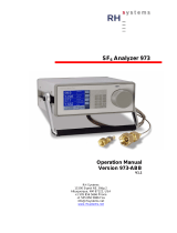
Parts Description
0403-031
Figure 1 Hand-Held Dewpoint Meter DM70
The following numbers refer to Figure 1 above.
1 = MI70 indicator
2 = DMP74 probe
3 = Sampling cell DSC74 (optional)
4 = Calibration button
5 = Recharger connector
6 = Connector ports for probes and cables
VAISALA_______________________________________________________________________ 11

USER'S GUIDE____________________________________________________________________
This page intentionally left blank.
12 __________________________________________________________________ M010091EN-F

Chapter 3 ____________________________________________________ Preparations Before Use
CHAPTER 3
PREPARATIONS BEFORE USE
Installing and Removing the Battery Pack
NOTE
If you have previously used a battery pack, put the metal contact at
the lower end of the batteries before installing the alkaline batteries.
If DM70 is ordered with a battery pack, it is already installed at the
factory.
1. Unscrew the back plate of the indicator.
2. Remove the old batteries. Detach the black connector by pulling
it up carefully from the wires.
0403-032
Figure 2 Installing the Battery Pack
3. Connect the black connector of the new battery pack. Make sure
the red and black wires are on the upper edge of the connector.
VAISALA_______________________________________________________________________ 13

USER'S GUIDE____________________________________________________________________
Do not push the connector with any conducting material. See
Figure 2 on page 13.
NOTE
If you have previously used alkaline batteries, remove the metal
contact before installing the battery pack.
4. Replace the battery pack, close the back plate, and tighten the
screw.
5. Charge the battery before use.
NOTE
Old batteries must be disposed of according to the local laws and
regulations.
Charging the Battery Pack
NOTE
Do not use DM70 during the first charging.
1. Plug the recharger connector to the base of the indicator.
2. Connect the recharger to a wall socket. A battery symbol in the
corner of the display will start rolling.
3. When the battery symbol stops rolling, the battery pack is fully
charged.
4. Disconnect the recharger.
The duration of recharging is typically 4 hours. However, the
recommended first charging time is 6 hours.
14 __________________________________________________________________ M010091EN-F

Chapter 3 ____________________________________________________ Preparations Before Use
Buttons and Navigation
To turn on the device, press the Power On/Off button. To open
menus, press an arrow button and then press the shortcut buttons. To
activate a function shown above the shortcut button, press the shortcut
button. To navigate in the menus, press arrow buttons.
0403-033
Figure 3 Buttons
The following numbers refer to Figure 3 above.
1 = Shortcut buttons
2 = Arrow buttons
3 = Power on/off button
Turning on the Device
1. Connect the probe to either one of the base connectors in the
indicator.
2. Press the Power On/Off button.
3. Press any of the arrow buttons and open a menu by pressing
Open.
4. Select Settings using the buttons and press .
5. Select User interface and press .
6. Select Language and press Set.
7. Select the language using the buttons. Confirm the
selection by pressing Select.
VAISALA_______________________________________________________________________ 15

USER'S GUIDE____________________________________________________________________
8. If you want to set the date at this point, return to the Settings
menu by pressing .
NOTE
The language can be selected also later. See section Language on
page 37.
9. To change the date, select Date and press Set. Then change
the date using the buttons. To confirm the selection, press
Select. As a default, the date format is year-month-day You
can select from two other alternative formats.
10. To change the time, select Time and press Set. Then change
the time by using the arrow buttons. Confirm the selection by
pressing OK. As a default, the time format is based on the
24-hour clock. If you want to use the 12-hour clock, select 12-
hour clock and then press On.
11. To return to the basic display, press Exit.
16 __________________________________________________________________ M010091EN-F

Chapter 4 _____________________________________________________ Dewpoint Measurement
CHAPTER 4
DEWPOINT MEASUREMENT
The following recommendations should be taken into account when
measuring in very dry environments.
- A clean environment is always best for humidity measurements.
- The number of connections should be minimized to avoid leaks.
- The flow rate must be adequate.
- Dead ends must be avoided as they cannot be flushed easily.
- The tube temperature must never lie under the dewpoint of the
sample gas. This may lead to condensation and false results.
- The sample tubing should be of as short length as possible. The
surface area should be minimized using the narrowest tubing that
the flow conditions allow.
- The surface finish of the pipework is important. Polished or
electro-polished steel is recommended for best results.
- Hygroscopic materials should be avoided in the sampling lines. Use
stainless steel membranes instead of rubber membranes.
- Impermeable materials should be selected to avoid inward diffusion
of moisture through the sampling tubes and enclosures. Such
impermeable materials are, for example, high-quality stainless steel
and metals. Avoid PVC or nylon tubes.
Measuring
If you start DM70 for the first time, see section Preparations Before
Use on page 13. Otherwise, follow the instructions below.
1. Connect the probe to the MI70 indicator.
2. Press the Power On/Off button.
VAISALA_______________________________________________________________________ 17

USER'S GUIDE____________________________________________________________________
3. Install the probe to the measuring position. If you are measuring
in pressurized processes, see section Connection to Pressurized
Processes Using the DSC74 Sampling Cell on page 52. When
using other sampling cells than DSC74, make sure that the
threads are compatible with the probe threads (G ½" ISO228/1).
Be careful not to damage the sintered filter when installing the
probe.
4. Before measuring, make sure that the air pressure settings of
DM70 are correct and that auto-calibration has taken place (see
section Automatic Auto-Calibration on page 27)
5. The basic display opens. Let the reading stabilize.
CAUTION
If you need to disconnect the probe from the indicator, first press the
Power On/Off button to turn the indicator off. This ensures that all
the settings and data are saved properly.
NOTE
When measuring low dewpoints, the stabilization times can be long,
for example, one to two hours. Therefore, turn off the automatic
power-off function (see section Automatic Power Off on page 38),
turn on the automatic auto-calibration (see section Automatic Auto-
Calibration on page 27), and turn on the automatic sensor purge (see
section Turning on/off Automatic Sensor Purge on page 30).
Thus, the stabilization can be monitored, the auto-calibration ensures
an accurate measurement, and the purge ensures the shortest possible
response times.
18 __________________________________________________________________ M010091EN-F
/