
M211289EN-B
User Guide
Vaisala HUMICAP
â
Dew Point Transmitter
DMT132

PUBLISHED BY
Vaisala Oyj
Vanha Nurmijärventie 21, FI-01670 Vantaa, Finland
P.O. Box 26, FI-00421 Helsinki, Finland
+358 9 8949 1
Visit our Internet pages at www.vaisala.com.
© Vaisala Oyj 2018
No part of this manual may be reproduced,
published or publicly displayed in any form or by
any means, electronic or mechanical (including
photocopying), nor may its contents be modified,
translated, adapted, sold or disclosed to a third
party without prior written permission of the
copyright holder. Translated manuals and
translated portions of multilingual documents are
based on the original English versions. In
ambiguous cases, the English versions are
applicable, not the translations.
The contents of this manual are subject to change
without prior notice.
Local rules and regulations may vary and they
shall take precedence over the information
contained in this manual. Vaisala makes no
representations on this manual’s compliance with
the local rules and regulations applicable at any
given time, and hereby disclaims any and all
responsibilities related thereto.
This manual does not create any legally binding
obligations for Vaisala towards customers or end
users. All legally binding obligations and
agreements are included exclusively in the
applicable supply contract or the General
Conditions of Sale and General Conditions of
Service of Vaisala.
This product contains software developed by
Vaisala or third parties. Use of the software is
governed by license terms and conditions
included in the applicable supply contract or, in
the absence of separate license terms and
conditions, by the General License Conditions of
Vaisala Group.

Table of Contents
1. About This Document..................................................................................... 5
1.1 Version Information.............................................................................................5
1.2 Related Manuals...................................................................................................5
1.3 Documentation Conventions............................................................................. 5
1.4 Trademarks...........................................................................................................6
2. Product Overview..............................................................................................7
2.1 Introduction to DMT132.......................................................................................7
2.2 Basic Features and Options............................................................................... 8
2.3 Transmitter Structure.......................................................................................... 8
2.4 LED Indicator Plug (Optional)............................................................................9
2.5 Special Cover Set for HMK15 (Optional)......................................................... 10
2.6 NPT Adapter (Optional)..................................................................................... 11
2.7 Loop-Powered Display (Optional).................................................................... 11
2.8 Connection Cables............................................................................................. 12
2.9 Sampling Accessories........................................................................................13
2.10 Safety...................................................................................................................13
2.10.1 ESD Protection.............................................................................................14
2.11 Regulatory Compliances...................................................................................14
3. Installation.......................................................................................................... 15
3.1 Selecting Location............................................................................................. 15
3.2 Installing Transmitter.........................................................................................16
3.3 Wiring..................................................................................................................19
3.3.1 Power Supply Requirements.................................................................... 20
3.4 Sampling from a Process...................................................................................21
3.5 Sampling Accessories for DMT132................................................................... 21
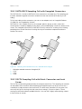
3.5.1 DMT242SC Sampling Cell........................................................................... 21
3.5.2 DMT242SC2 Sampling Cell with Swagelokâ Connectors..................... 22
3.5.3 DSC74 Sampling Cell with Quick Connector and Leak Screw...............22
3.5.4 DSC74B Two-Pressure Sampling Cell.......................................................23
4. Operation........................................................................................................... 29
4.1 Getting Started..................................................................................................29
4.2 Serial Communication...................................................................................... 29
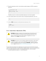
4.2.1 Connecting to Serial Interface.................................................................. 29
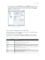
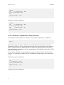
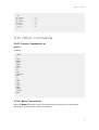
4.2.2 Terminal Application Settings...................................................................30
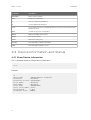
4.3 List of Serial Commands....................................................................................31
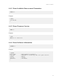
4.4 Device Information and Status........................................................................32
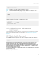
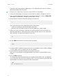
4.4.1 Show Device Information...........................................................................32
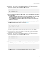
4.4.2 Show Available Measurement Parameters..............................................33
4.4.3 Show Firmware Version............................................................................. 33
4.4.4 Show Software Information...................................................................... 33
4.5
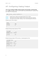
Configuring Analog Output.............................................................................34
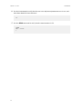
4.5.1 Set Analog Output Measurement Parameter and Scaling.................... 34
4.5.2 Set Analog Output Error Notification...................................................... 35
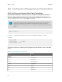
4.6 Configuring Measurement Parameters.......................................................... 36
4.6.1 Set Pressure Value for Dew Point Calculation.........................................36
Table of Contents
1

4.7 Serial Line Output Commands.........................................................................37
4.7.1 Output a Reading Once............................................................................. 37
4.8 Troubleshooting and Maintenance Commands.............................................37
4.8.1 Display Currently Active Errors.................................................................37
4.8.2 Test Analog Output.................................................................................... 38
4.8.3 Set LED Indicator Level..............................................................................38
4.9 Calibration and Adjustment Commands........................................................39
4.9.1 Calibrate Humidity Measurement.............................................................39
4.9.2 Calibrate Temperature Measurement...................................................... 40
4.9.3 Adjust Capacitance Measurement.............................................................41
4.9.4 View User Adjustment Parameters.......................................................... 42
4.9.5 Set User Adjustment Parameters............................................................. 42
4.10 Other Commands..............................................................................................43
4.10.1 Display Command List...............................................................................43
4.10.2 Reset Transmitter....................................................................................... 43
4.10.3 Restore Factory Settings...........................................................................44
5. Maintenance......................................................................................................45
5.1 Cleaning Transmitter........................................................................................ 45
5.2 Changing Filter..................................................................................................45
5.3 Changing Sensor...............................................................................................46
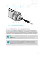
5.4 Calibration and Adjustment.............................................................................47
5.4.1 Field Check Using DM70............................................................................48
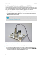
5.4.2 Humidity Calibration and Adjustment (RHCAL).................................... 50
5.4.3 Temperature Calibration and Adjustment (CT)...................................... 53
5.4.4 Capacitance Adjustment (CRH)................................................................55
6. Troubleshooting.............................................................................................. 59
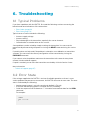
6.1 Typical Problems...............................................................................................59
6.2 Error State..........................................................................................................59
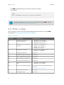
6.3 Error Codes........................................................................................................60
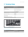
7. Technical Data..................................................................................................63
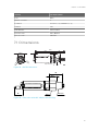
7.1 Dimensions........................................................................................................ 65
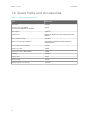
7.2 Spare Parts and Accessories........................................................................... 66
Warranty
........................................................................................................................ 67
Technical Support......................................................................................................67
Recycling....................................................................................................................... 67
DMT132 User Guide M211289EN-B
2

List of Figures
Figure 1 Vaisala HUMICAPâ Dew Point Transmitter DMT132................................. 8
Figure 2 DMT132 Transmitter Structure.........................................................................9
Figure 3 DMT132 with LED Indicator Plug...................................................................10
Figure 4 Special Cover Set for HMK15.......................................................................... 10
Figure 5 DMT132 with NPT Adapter............................................................................... 11
Figure 6 Nokeval 301 Loop-Powered Display.............................................................12
Figure 7 Cable with Threaded Connector....................................................................13
Figure 8 USB Service Cable............................................................................................. 13
Figure 9 Removing the Transport Protection Cap.................................................... 16
Figure 10 Installing the Transmitter.................................................................................17
Figure 11 Tightening by Hand...........................................................................................17
Figure 12 Tightening with Plastic Wrench.....................................................................18
Figure 13 Connecting the Cable and LED Indicator Plug.......................................... 19
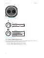
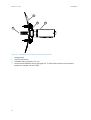
Figure 14 Connectors I and II........................................................................................... 20
Figure 15 Connector Pinout..............................................................................................20
Figure 16 Sampling Cells DMT242SC2 (Left) and DMT242SC (Right)..................22
Figure 17 DSC74 Sampling Cell with Accessories.......................................................23
Figure 18 DSC74B................................................................................................................24
Figure 19 Removing the Leak Screw..............................................................................25
Figure 20 Default Assembly of DSC74C........................................................................ 26
Figure 21 Alternative Assembly of DSC74C (for Tight Spaces)..............................27
Figure 22 DM240FA Duct Installation Flange with DMT132.....................................28
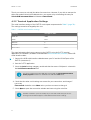
Figure 23 PuTTY Terminal Application........................................................................... 31
Figure 24 Opening the Filter............................................................................................ 45
Figure 25 Filter Structure.................................................................................................. 46
Figure 26 Removing the HUMICAPâ 180R Sensor.....................................................47
Figure 27 Calibrating DMT132 Using HMK15 and USB Cable................................... 50
Figure 28 Accuracy Over Temperature Range.............................................................63
Figure 29 DMT132 Dimensions......................................................................................... 65
Figure 30 Dimensions with NPT Adapter and LED Plug........................................... 65
List of Figures
3

List of Tables
Table 1 Document Versions................................................................................................5
Table 2 Related Manuals..................................................................................................... 5
Table 3 DMT132 Measurement Parameters.................................................................... 7
Table 4 Connector Pinouts................................................................................................19
Table 5 DMT132 Serial Interface Settings.....................................................................30
Table 6 DMT132 Serial Commands..................................................................................31
Table 7 Pressure Conversion Coecients....................................................................36
Table 8 Error Codes........................................................................................................... 60
Table 9 Measurement Performance...............................................................................63
Table 10 Operating Environment..................................................................................... 63
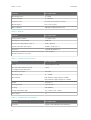
Table 11 Outputs.................................................................................................................. 64
Table 12 Mechanical Specifications.................................................................................64
Table 13 Output Cable Specifications.............................................................................64
Table 14 Spare Parts and Accessories............................................................................ 66
DMT132 User Guide M211289EN-B
4

1. About This Document
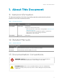
1.1 Version Information
This document provides instructions for installing, operating, and maintaining Vaisala
HUMICAPâ Dew Point Transmitter DMT132.
Table 1 Document Versions
Document Code Date Description
M211289EN-B August 2018 This manual.
Changes since the previous version:
• Note about pressure compensation setting added in Calibration and
Adjustment (page 47)
• Technical specifications updated with regard to measurement
range, response time, and operating temperature
• Patent Notice section removed
M211289EN-A March 2011 First version.
1.2 Related Manuals
Table 2 Related Manuals
Document Code Name
M211288EN Vaisala HUMICAP
â
Dewpoint Transmitter DMT132 Quick Guide
M210185EN Vaisala Humidity Calibrator HMK15 User’s Guide
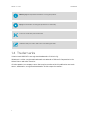
1.3 Documentation Conventions
Warning alerts you to a serious hazard. If you do not read and follow
instructions carefully at this point, there is a risk of injury or even death.
WARNING!
Caution warns you of a potential hazard. If you do not read and follow
instructions carefully at this point, the product could be damaged or important data
could be lost.
CAUTION!
Chapter 1 – About This Document
5

Note highlights important information on using the product.
Tip gives information for using the product more eciently.
Lists tools needed to perform the task.
Indicates that you need to take some notes during the task.
1.4 Trademarks
Vaisalaâ and HUMICAPâ are registered trademarks of Vaisala Oyj.
Windowsâ is either a registered trademark or trademark of Microsoft Corporation in the
United States and other countries.
All other product or company names that may be mentioned in this publication are trade
names, trademarks, or registered trademarks of their respective owners.
DMT132 User Guide M211289EN-B
6

2. Product Overview
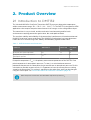
2.1 Introduction to DMT132
The Vaisala HUMICAPâ Dew Point Transmitter DMT132 measures dew point temperature
within measurement range -30 ... +50 °C (-22 ... +122 °F) T
d
. The DMT132 is designed for OEM
applications that require dew point measurement in this range, such as refrigeration dryers.
The transmitter is easy to install, and the mechanics have been designed for harsh
environments requiring protection against dust, dirt, and splashed water.
The excellent stability and reliability of the transmitter’s performance is based on advanced
HUMICAPâ polymer sensor technology. The HUMICAPâ technology has low maintenance
needs due to its excellent long-term stability and durability against condensation.
Table 3 DMT132 Measurement Parameters
Parameter Abbreviation Metric Unit Non Metric
Unit
Dew point/frost point temperature T
d/f
°C °F
Dew point/frost point temperature in
atmospheric pressure
T
d/f
atm °C °F
Dew point temperature (T
d/f
) is the primary measurement parameter of the DMT132. Dew
point temperature in atmospheric pressure (T
d/f
atm) is a calculated measurement
parameter that presents the dew point the gas would have at atmospheric pressure. For this
calculation to provide accurate results, it is important to have the correct pressure setting
stored in the transmitter. This setting is
specified on the order form, and it can be changed
using the service port. See Set Pressure Value for Dew Point Calculation (page 36).
When dew point is below 0 °C, the transmitter outputs frost point for T
d
.
Chapter 2 – Product Overview
7

Figure 1 Vaisala HUMICAPâ Dew Point Transmitter DMT132
2.2 Basic Features and Options
• Dew point measurement range -30 ... +50 °C (-22 ... +122 °F) T
d
• Output in T
d/f
or T
d/f
atm (calculated measurement parameter)
• HUMICAPâ polymer sensor
• Small size to fit in tight installations
• One scalable 2-wire current loop output, 4 ... 20 mA
•
Configurable analog output level for error notification
• Field check suitability with MI70 hand-held indicator
• Optional accessories:
• USB service cable for
configuration and calibration
• LED indicator plug that enables a visual indication of transmitter status: LED lit when
dew point is above set limit, blinking for malfunction alarm
• Special cover set for HMK15 Humidity Calibrator
• Adapter for mounting on NPT 1/2" threaded mounting points
• Loop-powered display
• Various sampling cells with
dierent installation options
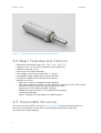
2.3
Transmitter Structure
The structure of the DMT132 is shown in Figure 2 (page 9). The transmitter body does not
have user serviceable parts inside, and is not designed to be opened. Opening the
transmitter will void the warranty.
DMT132 User Guide M211289EN-B
8

1
2
4
3
6
5
7
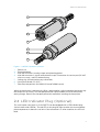
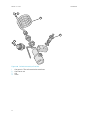
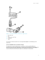
Figure 2 DMT132 Transmitter Structure
1 30-mm nut
2 Transmitter body
3 4-pin M8 connector I: analog output and operating power
4 4-pin M8 connector II (shown with protective cap): Connection for service port (RS-485,
service use only ) and LED indicator plug
5 Sealing ring (included with every transmitter)
6 Connection thread (ISO G1/2")
7 Tube filter that protects the HUMICAPâ and Pt1000 sensors
When the transmitter is delivered, the filter is protected by a yellow transport protection cap
that keeps the sensor dry. The transport protection cap should be left on the transmitter
during storage. Remove the transport protection cap before installing the transmitter.
2.4
LED Indicator Plug (Optional)
The service port (connector II) of the DMT132 can be equipped with a LED indicator plug
(Vaisala order code 230388). The red LED on the plug will light up when the measured dew
point temperature is above the set limit. If the transmitter is in error condition, the LED will
blink.
Chapter 2 – Product Overview
9

Figure 3 DMT132 with LED Indicator Plug
The dew point limit for the LED indication can be changed using the service port; see
Serial Communication (page 29).
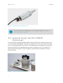
2.5 Special Cover Set for HMK15
(Optional)
To use the Vaisala Humidity Calibrator HMK15 with the DMT132 you need the special cover
set (Vaisala order code 230914). The cover set includes one salt jar cover where one of the
holes is specially designed for the DMT132, and rubber plugs for covering the unused holes.
The hole for DMT132 is raised higher than the others, and has an ISO G 1/2" thread. The
DMT132 can be mounted on the salt jar tightly using the thread, and without having to
remove the
filter.
Figure 4 Special Cover Set for HMK15
DMT132 User Guide M211289EN-B
10

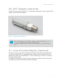
2.6 NPT Adapter (Optional)
The DMT132 can be connected to NPT 1/2" threaded mounting points using the optional NPT
adapter (Vaisala order code 210662).
Figure 5 DMT132 with NPT Adapter
When the NPT adapter is used, the
filter is partially covered by the adapter; see Figure 5
(page 11). This doubles the response time of the transmitter.
The adapter is suitable for use in compressed air lines and other systems with sucient
flow.
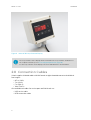
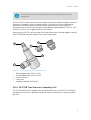
2.7 Loop-Powered Display (Optional)
The DMT132 can be connected to a loop-powered external LED display (type Nokeval 301,
Vaisala order code 226476). The display provides a reading of the output measurement
parameter. The display is powered by the 4 ... 20 mA current signal, so there is no need for
an external power supply.
The display is delivered at its default settings.
Configure the display functions and scaling
according to the documentation delivered with the display.
Chapter 2 – Product Overview
11

Figure 6 Nokeval 301 Loop-Powered Display
The loop resistance of the display must be included in the loop resistance calculation for
the complete current loop. See Power Supply Requirements (page 20).
For the loop resistance of the display, refer to the manufacturer’s documentation.
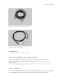
2.8 Connection Cables
Vaisala supplies shielded cables with M8 female straight threaded connector. Available in
four lengths:
• 0.3 m (1.0 ft)
• 3 m (9.8 ft)
• 5 m (16.4 ft)
• 10 m (32.8 ft)
Also available are cables for service port and
field check use:
• USB service cable
• MI70 connection cable
DMT132 User Guide M211289EN-B
12

Figure 7 Cable with Threaded Connector
Figure 8 USB Service Cable
More Information
‣
Spare Parts and Accessories (page 66)
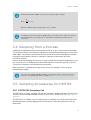
2.9
Sampling Accessories
DMT132 is compatible with various sampling accessories. For more information on
performing sampling, and a description of the accessories, see Sampling Accessories for
DMT132 (page 21).
For order codes of sampling accessories, see Spare Parts and Accessories (page 66).
2.10
Safety
The Vaisala HUMICAPâ Dew Point Transmitter DMT132 delivered to you has been tested for
safety and approved as shipped from the factory. Note the following precautions:
Chapter 2 – Product Overview
13

Ground the product and verify installation grounding periodically to
minimize shock hazard.
WARNING!
Do not modify the unit or use it in ways not described in the documentation.
Improper
modification may lead to safety hazards, equipment damage, failure to
perform according to specification, or decreased equipment lifetime.
CAUTION!
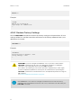
2.10.1 ESD Protection
Electrostatic Discharge (ESD) can cause immediate or latent damage to electronic circuits.
Vaisala products are adequately protected against ESD for their intended use. However, it is
possible to damage the product by delivering an electrostatic discharge when touching,
removing or inserting any objects inside the equipment housing.
Avoid touching component contacts or connectors when working with the device.
2.11 Regulatory Compliances
The Vaisala HUMICAPâ Dew Point Transmitter DMT132 is in conformity with the provisions
of the following EU directive:
• EMC-Directive (2004/108/EC)
Conformity is shown by compliance with the following standards:
• EN 61326-1: Electrical equipment for measurement, control, and laboratory use – EMC
requirements – for use in industrial locations.
• EN 550022: Information technology equipment – Radio disturbance characteristics –
Limits and methods of measurement
DMT132 User Guide M211289EN-B
14

3. Installation
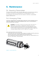
3.1 Selecting Location
It is important that the conditions at the point of installation represent well the gas to be
measured. Temperature changes do not
aect the dew point measurement, but pressure
changes will have an
eect on dew point. All leaks in the system must be eliminated to avoid
ambient humidity
aecting the measurement.
Direct installation to the measured gas is the recommended installation method if the
temperature of the gas is suitable for DMT132 and no additional filtering is needed due to
very dusty or oily gas. Oil as such is not harmful for the HUMICAPâ sensor, but response
time may be slower if there are oil particles in the system, or if oil is collected to the
filter
over a longer period of time. The maximum measurement pressure is 20 bar
a
/ 290 psi
a
(absolute pressure) for direct measurement.
If the gas temperature is higher than the specified maximum operating temperature of the
transmitter, gas sampling and cooling it to ambient temperature (for example, 20 °C / 68 °F)
is recommended. Note that the dew point temperature must be clearly lower than the
ambient temperature to avoid condensation in the sampling line. Sampling from the process
is easy by using Vaisala sampling cell options.
The DMT132 is light in weight, which means that it can be installed in a sample pipeline in the
sampling cells without the need for any additional mechanical support.
More Information
‣
Sampling Accessories for DMT132 (page 21)
Chapter 3 – Installation
15

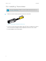
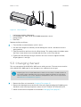
3.2 Installing Transmitter
Before proceeding with the installation, select first a suitable measurement location. See
Selecting Location (page 15).
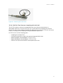
1. Remove the yellow transport protection cap from the transmitter.
Figure 9 Removing the Transport Protection Cap
2. If you are using the optional NPT adapter, apply PTFE tape or suitable paste sealant to
the outer thread of the adapter. Follow the application instructions of the sealant.
3. Install the adapter to the mounting point.
DMT132 User Guide M211289EN-B
16

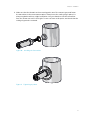
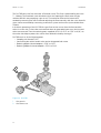
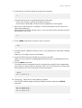
4. Make sure that the threads on the mounting point are of the correct type, and fasten
the transmitter to the measurement point. Always leave the sealing ring in place, it is
always needed to achieve a tight installation. Use your hands to turn the transmitter
from the 30 mm nut until it feels tight. Do not use force at this point, and check that the
sealing ring remains centered.
Figure 10 Installing the Transmitter
Figure 11 Tightening by Hand
Chapter 3 – Installation
17

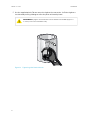
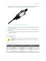
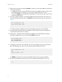
5. Use the supplied plastic 30 mm wrench to tighten the connection. Sucient tightness
is achieved by turning 20 degrees after the point achieved by hand.
Only tighten the transmitter from the 30 mm nut. Do NOT apply force
to other points in the transmitter body.
CAUTION!
20
º
Figure 12 Tightening with Plastic Wrench
DMT132 User Guide M211289EN-B
18
Page is loading ...
Page is loading ...
Page is loading ...
Page is loading ...
Page is loading ...
Page is loading ...
Page is loading ...
Page is loading ...
Page is loading ...
Page is loading ...
Page is loading ...
Page is loading ...
Page is loading ...
Page is loading ...
Page is loading ...
Page is loading ...
Page is loading ...
Page is loading ...
Page is loading ...
Page is loading ...
Page is loading ...
Page is loading ...
Page is loading ...
Page is loading ...
Page is loading ...
Page is loading ...
Page is loading ...
Page is loading ...
Page is loading ...
Page is loading ...
Page is loading ...
Page is loading ...
Page is loading ...
Page is loading ...
Page is loading ...
Page is loading ...
Page is loading ...
Page is loading ...
Page is loading ...
Page is loading ...
Page is loading ...
Page is loading ...
Page is loading ...
Page is loading ...
Page is loading ...
Page is loading ...
Page is loading ...
Page is loading ...
Page is loading ...
Page is loading ...
Page is loading ...
Page is loading ...
-
 1
1
-
 2
2
-
 3
3
-
 4
4
-
 5
5
-
 6
6
-
 7
7
-
 8
8
-
 9
9
-
 10
10
-
 11
11
-
 12
12
-
 13
13
-
 14
14
-
 15
15
-
 16
16
-
 17
17
-
 18
18
-
 19
19
-
 20
20
-
 21
21
-
 22
22
-
 23
23
-
 24
24
-
 25
25
-
 26
26
-
 27
27
-
 28
28
-
 29
29
-
 30
30
-
 31
31
-
 32
32
-
 33
33
-
 34
34
-
 35
35
-
 36
36
-
 37
37
-
 38
38
-
 39
39
-
 40
40
-
 41
41
-
 42
42
-
 43
43
-
 44
44
-
 45
45
-
 46
46
-
 47
47
-
 48
48
-
 49
49
-
 50
50
-
 51
51
-
 52
52
-
 53
53
-
 54
54
-
 55
55
-
 56
56
-
 57
57
-
 58
58
-
 59
59
-
 60
60
-
 61
61
-
 62
62
-
 63
63
-
 64
64
-
 65
65
-
 66
66
-
 67
67
-
 68
68
-
 69
69
-
 70
70
-
 71
71
-
 72
72


Ask a question and I''ll find the answer in the document
Finding information in a document is now easier with AI
Related papers
Other documents
-
HQ W9-AD-12-12B Datasheet
-
-
 RH Systems 973 Owner's manual
-
Follett 18690 Installation, Operation And Service Manual
-
-
 RH Systems 373 Owner's manual
-
Swagelok MS-CRD-PTI-AI User manual
-
Trotec TC-001 User manual
-
 Nokeval DCS770 User manual
-
 Alpha Moisture Systems dewSMART DS1000 User manual


