Page is loading ...

USER'S GUIDE
Vaisala DRYCAP® Dewpoint Transmitte
r
DMT142
M210397EN-D

PUBLISHED BY
Vaisala Oyj Phone (int.): +358 9 8949 1
P.O. Box 26 Fax: +358 9 8949 2227
FIN-00421 Helsinki
Finland
Visit our Internet pages at http://www.vaisala.com/
© Vaisala 2006
No part of this manual may be reproduced in any form or by any means, electronic or
mechanical (including photocopying), nor may its contents be communicated to a third
party without prior written permission of the copyright holder.
The contents are subject to change without prior notice.
Please observe that this manual does not create any legally binding obligations for
Vaisala towards the customer or end user. All legally binding commitments and
agreements are included exclusively in the applicable supply contract or Conditions of
Sale.

_________________________________________________________________________________
VAISALA_________________________________________________________________________ 1
Table of Contents
CHAPTER 1
GENERAL INFORMATION............................................................................5
About This Manual...................................................................5
Contents of This Manual.......................................................5
Version Information...............................................................6
Related Manuals ...................................................................6
General Safety Considerations.............................................7
Feedback...............................................................................7
Product Related Safety Precautions ......................................7
Recycling ..................................................................................8
Regulatory Compliances.........................................................8
Electromagnetic Compatibility...............................................8
Trademarks...............................................................................8
Warranty....................................................................................9
CHAPTER 2
PRODUCT OVERVIEW..................................................................................3
Introduction to Dewpoint Transmitter DMT142.....................3
The Basic Features and Options............................................3
CHAPTER 3
FUNCTIONAL DESCRIPTION.......................................................................5
Advanced DRYCAP
®
Technology...........................................5
Auto-Calibration ....................................................................5
Sensor Purge ........................................................................6
Sensor Warming in High Humidities .....................................6
CHAPTER 4
INSTALLATION..............................................................................................7
Selecting Location ...................................................................7
Wiring ........................................................................................9
Optional Connection Cable.................................................10
Power Supply Requirements...............................................11
Mounting .................................................................................13
Direct Measurement in Process Pipeline............................13
Sampling from Pressurized Processes...............................14
DMT242SC Sampling Cell.............................................14
DMT242SC2 Sampling Cell with Swagelok
Connectors.....................................................................15
DSC74 Sampling Cell with Quick Connector and Leak
Screw .............................................................................15
DSC74B Two-Pressure Sampling Cell ..........................17
DSC74C Two-Pressure Sampling Cell with Coil ...........18
DM240FA Duct Installation Flange................................20

User's Guide_______________________________________________________________________
2 ____________________________________________________________________ M210397EN-D
CHAPTER 5
SERIAL COMMANDS ..................................................................................21
Connecting Serial Interface...................................................21
Commands for Basic Settings ..............................................22
Select Nonmetric Unit..........................................................22
Select Metric Unit ................................................................22
Scale Dewpoint Analog Output ...........................................22
Select Analog Output Quantity............................................22
Set Analog Output Mode.....................................................23
DMT142 Firmware Version Output......................................23
Pressure Compensation......................................................24
Test Analog Output Current ................................................25
Test Analog Voltage Output ................................................25
Restart Program ..................................................................25
Serial Line Output Commands..............................................26
Start Measurement Output..................................................26
Stop Measurement Output ..................................................26
Set Output Interval...............................................................26
Polling Mode for DMT142 Transmitter..................................27
Set Transmitter Address......................................................27
Set Serial Interface Mode....................................................27
OPEN Opening the Transmitter in POLL-State...................28
SEND Outputting a Reading Once......................................28
CHAPTER 6
MAINTENANCE............................................................................................29
Calibration and Adjustment...................................................29
Filter Change...........................................................................29
Vaisala Service Centers.........................................................30
CHAPTER 7
TROUBLESHOOTING..................................................................................31
Error States .............................................................................31
Technical Support ..................................................................31
CHAPTER 8
TECHNICAL DATA ......................................................................................33
Specifications .........................................................................33
Spare Parts and Accessories................................................36
Dimensions in mm (inches)...................................................37
Wiring Quick Reference.........................................................37

_________________________________________________________________________________
VAISALA_________________________________________________________________________ 3
List of Figures
Figure 1 Dewpoint Transmitter DMT142 Components.............................4
Figure 2 Mounting Dewpoint Transmitter DMT142 ..................................8
Figure 3 Wiring of Voltage Output Version...............................................9
Figure 4 Wiring of Current Output Version...............................................9
Figure 5 Pin Order of DMT142 Connector (Transmitter Side) ...............10
Figure 6 Snap-On Type Cable................................................................11
Figure 7 Screw Fitting Type Cable.........................................................11
Figure 8 Example Of Sensor Purge Current (at Room Temperature with
24 VDC)....................................................................................12
Figure 9 Example of Auto-Calibration Current (at Room Temperature
with 24 VDC) ............................................................................12
Figure 10 DMT142 Installed Directly to Pipeline ......................................13
Figure 11 DMT242SC Sampling Cell .......................................................14
Figure 12 DMT242SC2 Sampling Cell with Swagelok Connectors..........15
Figure 13 DSC74 Sampling Cell with Accessories...................................16
Figure 14 DSC74B....................................................................................17
Figure 15 Removing the Leak Screw.......................................................17
Figure 16 Default Assembly of DSC74C..................................................18
Figure 17 Alternative Assembly of DSC74C (for Tight Spaces)...............19
Figure 18 DM240FA with DMT142...........................................................20
Figure 19 DMT142 Dewpoint Measurement Accuracy Graph .................34
Figure 20 DMT142 Dimensions................................................................37
List of Tables
Table 1 Manual Revisions.......................................................................6
Table 2 Related Manuals ........................................................................6
Table 3 Wiring Table...............................................................................9
Table 4 Description of DMT142 Connection Cable...............................10
Table 5 DMT142 Serial Interface Setting..............................................21
Table 6 Pressure Conversion Coefficients............................................24
Table 7 Measured Variable...................................................................33
Table 8 Operating Environment Specifications.....................................34
Table 9 Output Specifications ...............................................................34
Table 10 General Specifications .............................................................35

User's Guide_______________________________________________________________________
4 ____________________________________________________________________ M210397EN-D
This page intentionally left blank.

Chapter 1 _________________________________________________________ General Information
VAISALA_________________________________________________________________________ 5
CHAPTER 1
GENERAL INFORMATION
This chapter provides general notes for the manual and the product.
About This Manual
This manual provides information for installing, operating, and
maintaining Dewpoint Transmitter DMT142.
Contents of This Manual
This manual consists of the following chapters:
- Chapter 1, General Information, provides general notes for the
manual and the product.
- Chapter 2, Product Overview, introduces the features and
advantages of Dewpoint Transmitter DMT142.
- Chapter 3, Functional Description, describes the advanced
functionality of Dewpoint Transmitter DMT142, including the
auto-calibration, sensor purge and sensor warming functions.
- Chapter 4, Installation, provides you with information that is
intended to help you install Dewpoint Transmitter DMT142.

User's Guide_______________________________________________________________________
6 ____________________________________________________________________ M210397EN-D
- Chapter 5, Serial Commands, contains the operating instructions
for the serial interface of Dewpoint Transmitter DMT142.
- Chapter 6, Maintenance, provides information that is needed in
basic maintenance of Dewpoint Transmitter DMT142, and contact
information for Vaisala Service Centers.
- Chapter 7, Troubleshooting, describes the error states and provides
contact information for technical support.
- Chapter 8, Technical Data, provides the technical data of Dewpoint
Transmitter DMT142.
Version Information
Table 1 Manual Revisions
Manual Code Description
M210397EN-A Vaisala DRYCAP
®
Dewpoint
Transmitter DMT142 Advanced User
Manual, April 2003
M210397EN-B Vaisala DRYCAP
®
Dewpoint
Transmitter DMT142 User's Guide,
October 2005
Td measurement and operating
pressure range specification revised
New sampling cell, installation flange
and connection cable options added
M210397EN-C Vaisala DRYCAP
®
Dewpoint
Transmitter DMT142 User's Guide,
March 2006; this manual
Corrected wiring diagrams
Related Manuals
Table 2 Related Manuals
Manual Code Manual Name
M210396EN-A Vaisala DRYCAP
®
Dewpoint
Transmitter DMT142 Quick
Reference Guide

Chapter 1 _________________________________________________________ General Information
VAISALA_________________________________________________________________________ 7
General Safety Considerations
Throughout the manual, important safety considerations are
highlighted as follows:
WARNING
Warning alerts you to a serious hazard. If you do not read and follow
instructions very carefully at this point, there is a risk of injury or
even death.
CAUTION
Caution warns you of a potential hazard. If you do not read and
follow instructions carefully at this point, the product could be
damaged or important data could be lost.
NOTE
Note highlights important information on using the product.
Feedback
Vaisala Customer Documentation Team welcomes your comments
and suggestions on the quality and usefulness of this publication. If
you find errors or have other suggestions for improvement, please
indicate the chapter, section, and page number. You can send
comments to us by e-mail: [email protected]
Product Related Safety Precautions
The Dewpoint Transmitter DMT142 delivered to you has been tested
for safety and approved as shipped from the factory. Note the
following precautions:
CAUTION
Do not modify the unit. Improper modification can damage the
product or lead to malfunction.

User's Guide_______________________________________________________________________
8 ____________________________________________________________________ M210397EN-D
Recycling
Recycle all applicable material.
Dispose of batteries and the unit according to statutory regulations.
Do not dispose of with regular household refuse.
Regulatory Compliances
Vaisala DRYCAP® Dewpoint Transmitter DMT142 complies with
the following performance and environmental test standards:
Electromagnetic Compatibility
EN 61326-1:1997 + Am1:1998, Electrical equipment for
measurement, control and laboratory use - EMC requirements -
Industrial environment.
[CISPR16/22 Class B, EN/IEC 61000-4-2, EN/IEC 61000-4-3,
EN/IEC 61000-4-4, EN/IEC 61000-4-5, EN/IEC 61000-4-6]
Trademarks
DRYCAP
®
is a registered trademark of Vaisala.

Chapter 1 _________________________________________________________ General Information
VAISALA_________________________________________________________________________ 9
Warranty
Vaisala hereby represents and warrants all Products
manufactured by Vaisala and sold hereunder to be
free from defects in workmanship or material
during a period of twelve (12) months from the date
of delivery save for products for which a special
warranty is given. If any Product proves however to
be defective in workmanship or material within the
period herein provided Vaisala undertakes to the
exclusion of any other remedy to repair or at its
own option replace the defective Product or part
thereof free of charge and otherwise on the same
conditions as for the original Product or part
without extension to original warranty time.
Defective parts replaced in accordance with this
clause shall be placed at the disposal of Vaisala.
Vaisala also warrants the quality of all repair and
service works performed by its employees to
products sold by it. In case the repair or service
works should appear inadequate or faulty and
should this cause malfunction or nonfunction of the
product to which the service was performed Vaisala
shall at its free option either repair or have repaired
or replace the product in question. The working
hours used by employees of Vaisala for such repair
or replacement shall be free of charge to the client.
This service warranty shall be valid for a period of
six (6) months from the date the service measures
were completed.
This warranty is however subject to following
conditions:
a) A substantiated written claim as to any alleged
defects shall have been received by Vaisala
within thirty (30) days after the defect or fault
became known or occurred, and
b) The allegedly defective Product or part shall,
should Vaisala so require, be sent to the works
of Vaisala or to such other place as Vaisala may
indicate in writing, freight and insurance
prepaid and properly packed and labelled,
unless Vaisala agrees to inspect and repair the
Product or replace it on site.
This warranty does not however apply when the
defect has been caused through
a) normal wear and tear or accident;
b) misuse or other unsuitable or unauthorized use
of the Product or negligence or error in storing,
maintaining or in handling the Product or any
equipment thereof;
c) wrong installation or assembly or failure to
service the Product or otherwise follow
Vaisala's service instructions including any
repairs or installation or assembly or service
made by unauthorized personnel not approved
by Vaisala or replacements with parts not
manufactured or supplied by Vaisala;
d) modifications or changes of the Product as well
as any adding to it without Vaisala's prior
authorization;
e) other factors depending on the Customer or a
third party.
Notwithstanding the aforesaid Vaisala's liability
under this clause shall not apply to any defects
arising out of materials, designs or instructions
provided by the Customer.
This warranty is expressly in lieu of and excludes
all other conditions, warranties and liabilities,
express or implied, whether under law, statute or
otherwise, including without limitation any implied
warranties of merchantability or fitness for a
particular purpose and all other obligations and
liabilities of Vaisala or its representatives with
respect to any defect or deficiency applicable to or
resulting directly or indirectly from the Products
supplied hereunder, which obligations and
liabilities are hereby expressly cancelled and
waived. Vaisala's liability shall under no
circumstances exceed the invoice price of any
Product for which a warranty claim is made, nor
shall Vaisala in any circumstances be liable for lost
profits or other consequential loss whether direct or
indirect or for special damages.

User's Guide_______________________________________________________________________
2 ____________________________________________________________________ M210397EN-D
This page intentionally left blank.

Chapter 2 ___________________________________________________________Product Overview
VAISALA_________________________________________________________________________ 3
CHAPTER 2
PRODUCT OVERVIEW
This chapter introduces the features and advantages of Dewpoint
Transmitter DMT142.
Introduction to Dewpoint Transmitter DMT142
Vaisala DRYCAP
®
dewpoint transmitter DMT142 is designed for a
wide range of OEM applications. The excellent stability and reliability
of its performance is based on advanced DRYCAP
®
polymer sensor
technology. The DRYCAP
®
technology has low maintenance needs
due to its excellent long term stability and durability against
condensation. The DMT142 transmitter is easy to install and the
mechanics have been designed for harsh environments requiring
protection against dust, dirt and splashed water.
The Basic Features and Options
- Small size to fit in tight installations.
- Analog outputs: 4 ... 20 mA or 0 - 1 V/0 - 5 V versions.
- Low maintenance requirements due to excellent long term stability.
- DRYCAP
®
polymer sensor with automatic auto-calibration and
sensor purge ensures long term stability.
- Sensor warming keeps the sensor dry in abnormally high humidity
situations.
- Field check suitability with DM70 hand-held meter.

User's Guide_______________________________________________________________________
4 ____________________________________________________________________ M210397EN-D
- RS232 serial line connection for service use with DMT142RS
cable.
- Optional sampling cells with different installation options available
as DMT142 installation accessories.
1
2
3
4
5
678
0507-093
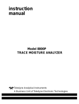
Figure 1 Dewpoint Transmitter DMT142 Components
The following numbers refer to Figure 1 above:
1 = Serial line connector (for service use)
2 = DRYCAP
®
sensor protected with sintered filter
3 = Sealing washer
4 = Protective cap for probe
5 = G1/2" ISO 228/1
6 = Protection plug for serial line connector
7 = Cable connector
8 = Connection cable (optional)

Chapter 3 _______________________________________________________ Functional Description
VAISALA_________________________________________________________________________ 5
CHAPTER 3
FUNCTIONAL DESCRIPTION
This chapter describes the advanced functionality of Dewpoint
Transmitter DMT142, including the auto-calibration, sensor purge and
sensor warming functions.
Advanced DRYCAP
®
Technology
Dewpoint Transmitter DMT142 utilizes an advanced, patented
measurement technology to ensure accurate measurement with
excellent long term stability. This results in very low maintenance
requirements for the transmitter. The lasting performance is achieved
with microprocessor technology and software that automatically
performs self-diagnostic functions in addition to the normal dewpoint
measurement. The self-diagnostic procedures that are conducted are
called auto-calibration, sensor purge and sensor warming.
Auto-Calibration
The auto-calibration feature of the DMT142 transmitter is an
automatic procedure which greatly reduces the possible drift in the dry
end of the dewpoint measurement. It is performed at one hour
intervals, and when the power is switched on. During auto-calibration
the sensor is warmed for a short period (< 1 min) and the sensor
capacitance values are evaluated at the elevated temperature. The
possible dry end drift is then corrected to correspond to the calibrated
values. During the auto-calibration the transmitter outputs the T
d
value
prior to the procedure.

User's Guide_______________________________________________________________________
6 ____________________________________________________________________ M210397EN-D
Auto-calibration is carried out only if several criteria for the
measurement environment are fulfilled. This ensures the reliability of
the adjustments, and maintains the excellent long term stability that
the patented technology offers. These criteria include for example a
stable enough moisture level in the measured atmosphere. If the
conditions are not fulfilled, the auto-calibration function is postponed
until satisfactory conditions are reached.
Sensor Purge
Sensor purge is also an automatic procedure that minimizes the drift at
the wet end readings of the dewpoint measurement. Sensor purge is
performed once a day or when the power is switched on. The sensor is
heated for several minutes which will then evaporate all excess
molecules out of the sensor polymer. This, together with the auto-
calibration results in a very small drift of the sensor due to the very
linear behaviour of the polymer technology.
Sensor Warming in High Humidities
Additionally the DMT142 transmitter has a warming feature which
prevents the sensor and filter from becoming wet in high humidities.
High humidity may be present when the dewpoint temperature rises
close to the gas temperature.
Sensor warming is switched on automatically when the humidity in
the measured gas increases to a level where dew can start to form. The
advantage of sensor warming is the rapid response of dewpoint
measurement. A wet sensor and filter would otherwise result in a
dewpoint equal to ambient temperature (that is RH = 100 %).
If in spite of sensor warming the sensor gets soaked, it will recover
fully back to normal operation after it dries out.

Chapter 4 ________________________________________________________________ Installation
VAISALA_________________________________________________________________________ 7
CHAPTER 4
INSTALLATION
This chapter provides you with information that is intended to help
you install Dewpoint Transmitter DMT142.
Selecting Location
In the mounting of Dewpoint Transmitter DMT142 it is important that
the point of installation represents well the gas to be measured.
Temperature changes do not affect the dewpoint measurement, but
pressure changes will have an effect on the measurement. All leaks in
the system must be eliminated to avoid ambient humidity affecting the
measurement.

User's Guide_______________________________________________________________________
8 ____________________________________________________________________ M210397EN-D
0507-094
Figure 2 Mounting Dewpoint Transmitter DMT142
The numbers in the following list refer to Figure 2 above:
1. Select a proper location to mount the DMT142 and remove the
yellow sensor protective cap.
2. Fit the sealing washer onto the probe.
3. Mount the transmitter to the measurement point. The transmitter
has parallel thread G1/2" ISO 228/1.
4. Connect the wires of the connection cable. When using the cable
provided with DMT142 refer to the following wiring section.
See the power supply requirements on page 11.
5. Plug in the cable to the transmitter and turn on the power supply.
6. Self diagnostics performed at start-up freeze the output during
the first minutes of operation. Typical warm-up time is about 5
minutes before normal operation.

Chapter 4 ________________________________________________________________ Installation
VAISALA_________________________________________________________________________ 9
Wiring
Table 3 Wiring Table
Pin Number Wire Colour
(in supplied cables
EN50044)
Name
1 Brown + VDC supply voltage
2 White - analog output signal
sense
(voltage output versions
only)
3 Blue - VDC supply voltage
4 Black + analog output signal
+
-
1
4
2
3
+
-
12-28VV
0507-095
Figure 3 Wiring of Voltage Output Version
The numbers below refer to Figure 3 above:
1 = Brown
2 = White
3 = Blue
4 = Black
2
3
4
1
+
-
-
+
mA
18-28V
0507-096
Figure 4 Wiring of Current Output Version
Note the three wire connection. The numbers below refer to Figure 4
above:
1 = Brown
2 = White
3 = Blue
4 = Black

User's Guide_______________________________________________________________________
10 ___________________________________________________________________ M210397EN-D
1
24
3
0507-097
Figure 5 Pin Order of DMT142 Connector (Transmitter
Side)
Optional Connection Cable
DMT142 is delivered optionally with two types of connection cables,
snap-on type or with screw fitting/locking.
Table 4 Description of DMT142 Connection Cable
Property Description / Value
M8 Female, straight connector, molded sensor cable, IEC 60947-5-2
Color Black
Number of contacts 4
Conductors 0.25 mm² (× 4) /
0.00039 inch² (× 4)
Insulation PVC
Cable diameter 5.0 mm / 0.2 inch
Protection class IP67 / NEMA 4
Wire color code EN50044
Snap-on type
Cable length 2 m / 6.6 ft
Screw fitting type
Shielded cable
0.3 m / 1 ft
3 m / 9.8 ft
5 m / 16.4 ft
10 m / 32.8 ft
/