Hamworthy 500001305-B QAA73.210 Programmable Room Unit Owner's manual
- Type
- Owner's manual

QAA73.210
Programmable Room Unit
For Single Boiler Installations
INSTALLATION, COMMISSIONING AND
SERVICING INSTRUCTIONS
IMPORTANT NOTE
THESE INSTRUCTIONS MUST BE READ
AND UNDERSTOOD BEFORE INSTALLING,
COMMISSIONING, OPERATING OR
SERVICING EQUIPMENT


HAMWORTHY HEATING LTD
QAA73.210
Programmable Room Unit
500001305/B
QAA73.210
PROGRAMMABLE ROOM UNIT
For Single Boiler Applications
Installation, Commissioning
and Operating Instructions
i
NOTE: THESE INSTRUCTIONS SHOULD BE READ AND UNDERSTOOD BEFORE
ATTEMPTING TO INSTALL, COMMISSION OR OPERATE THIS UNIT
PUBLICATION NO. 500001305
ISSUE ‘B’
June 2022

HAMWORTHY HEATING LTD
QAA73.210
Programmable Room Unit
500001305/B
ii
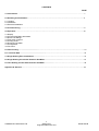
CONTENTS
PAGE
1.0 Introduction……...…………………………………………………………………………………………….……..1
2.0 Handling and Installation………………………………………………………………………………………………………………… 2
2.1 Location
2.2 Installation
2.3 Electrical installation
3.0 Commissioning………………………………………………………………………………………………………………………………...5
4.0 Operation………………………………………………………………………………………………………………………………..……....10
4.1 Display
4.2 Programming BMU parameters
4.3 Room unit settings
4.4Time switch program
4.5 Cooling circuit
4.6 Domestic Hot Water
4.7 Configuration
4.8 Functions
5.0 Fault Finding……………………………...…………………………………………………………………………………………......12
6.0 Technical Data………………………………………..………………………………………………………………………….….12
7.0 Single Heating Zone Installations……………….…………………………………………………………………….……….....13
8.0 Single Heating Circuit with Domestic Hot Water………………………….………….……………...……………..…..27
9.0 Twin Heating Circuits with Domestic Hot Water……………..…………………………………………….……….….…..30
Appendix A: Sensors…………………………………………………………………………………………………………………….…….…34

HAMWORTHY HEATING LTD
QAA73.210
Programmable Room Unit
500001305/B
iii

HAMWORTHY HEATING LTD
QAA73.210
Programmable Room Unit
500001305/B
iv

HAMWORTHY HEATING LTD
QAA73.210
Programmable Room Unit
500001305/B
1
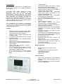
1.0 Introduction
The Hamworthy QAA73.210 is a digital multi-
functional room unit for one or 2 heating circuits and
d.h.w. control.
The boiler control LMU64 delivers the outside
temperature and other information to the
QAA73.210 room unit via the OpenTherm
communication interface. Based on the outside
temperature, the room temperature and a number of
other parameters, the interface calculates the
required flow temperature setpoints for one or 2
heating circuits and transmits them to the boiler
control. In addition, the d.h.w. temperature setpoint
is transmitted to the boiler control.
The optimization and weather compensation
functions offer energy savings without sacrificing
comfort. The room sensor required for that purpose
is integrated within the unit.
Features
• Operating sections (operating levels) based
on ergonomic and functional considerations
• Clear assignment of basic functions:
• Operating mode, setpoint adjustment and
occupancy button
• A number of actual values can be accessed
via the Info button
• Additional functions can be programmed after
opening the cover
• Special service level with protected access
• Every setting or change is displayed and thus
acknowledged
• Yearly clock with automatic summer- /
wintertime changeover
• One heating program per heating circuit with
up to 4 heating periods per day can be
selected on an individual basis
• D.h.w. program with up to 4 heating periods
per day can be selected on an individual
basis
• Holiday program
• The heating programs and the d.h.w. program
can be reset to their default settings
• Programming lock (e.g. for child-proofing)
• Special mode for setting the parameters of
Siemens boiler control systems
• Weather-compensated flow temperature
control while giving consideration to the
building’s thermal dynamics
• Weather-compensated flow temperature
control with room compensation
• Pure room temperature control
• Effect of room temperature deviation can be
adjusted
• Optimum start / stop control
• ECO functions (24-hour limit switch,
automatic summer / winter changeover)
• Room temperature switching differential for
limiting the room temperature
• Adjustable maximum limit of flow temperature
(especially in connection with floor heating
systems)
• Limitation of the rate of increase of the flow
temperature setpoint
• Frost protection for the building, frost warning
• D.h.w. control with release and pre-selection
of setpoint for the boiler controller
• Anit-legionella function
• Integrated yearly clock with a reserve of at
least 12 hours
• Elegant housing made of recyclable plastic
• Communication with the boiler control via
OpenTherm interface
• Power supply via OpenTherm interface
Range of Products
• Boiler Management Unit Premix TOP
LMU64
• Third party boiler control with OpenTherm
interface Room unit with
OpenTherm interface
QAA73.210
Product Liability
• When using the products, all requirements
specified under ‘Technical Data’ must be
observed
• The local regulations for electrical installation
must be complied with.

HAMWORTHY HEATING LTD
QAA73.210
Programmable Room Unit
500001305/B
2
2.0 Handling and installation
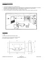
2.1 Location
• In the main occupancy room or reference room
• The place of installation should be chosen so that the sensor can capture the room temperature as accurately
as possible, without being affected by direct solar radiation or other heating or cooling sources
• Mounting height should be approximately 1.5 meters above the floor
• The unit can be fitted to most commercially available recessed conduit boxes or directly on the wall
2.2 Installation
• Wall
• Boiler control panel (with the help of clips)
The controller may not be exposed to dripping water
Permissible ambient temperature: 0...50 °C

HAMWORTHY HEATING LTD
QAA73.210
Programmable Room Unit
500001305/B
3
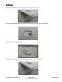
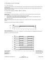
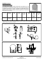
Open the unit at the bottom and remove the base from the housing front.
Pull the interface cable through the opening of the base and connect it to the screw terminals.
Fit the base to the walls with screws
Engage the housing front at the top of the base and close the unit to the bottom.
.
Wall Mounting

HAMWORTHY HEATING LTD
QAA73.210
Programmable Room Unit
500001305/B
4
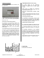
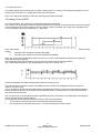
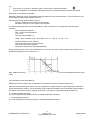
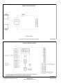
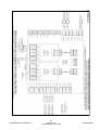
2.3 Electrical Installation
The local regulations for electrical installations must
be complied with.
1 COA Open Therm terminal A (interchangeable)
2 COB Open Therm terminal B (interchangeable)
Note: 23mA max.
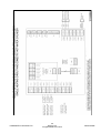
OpenTherm Communication Interface
For protection of the OpenTherm interface from
electromagnetic disturbance, cables used for the
OPENTHERM INTERFACE connections should be
completed using shielded two core cable.
Preference should be given to wire mesh shielded
twisted cables.
In the installation the two ends of the cable must be
connected to a reference potential (building ground).
To further protect the OPENTHERM INTERFACE
from electromagnetic disturbance these should be
separated from mains cables, preferably run in
separate conduits or ducts. Where mains cables
and OPENTHERM INTERFACE cables must be run
in the same duct a central divider should be used to
separate the OPENTHERM INTERFACE cables
from the mains cables.
S = Signal Lines
N = Mains Cables
M = Metal Duct with Metal Wall
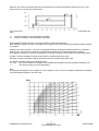
OPENTHERM INTERFACE Power Supply
The power supply for the OpenTherm
communication interface and the QAA73 room
controller is supplied from the boiler LMU64
controller.
Cables used for installing the OpenTherm
communication interface power supply must have
cross-sectional area of 1.5mm².
OpenTherm Communication Interface Cable
Lengths
Using non interchangeable copper cable 1.5mm² the
maximum permitted Interface cable length, including
all branches, is 50 metres.
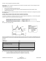
Connecting the Interface cable
The OpenTherm communication interface cable
must be connected to terminals GND(-) and LINE(+)
of the LMU64 and terminals 1 & 2 of the QAA73
room controller. The room controller terminals are
volt free therefore polarity is not critical.
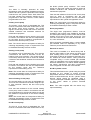
Communication with boiler control
For communication between the QAA73.210 and
boiler control, the OpenTherm Plus protocol is used.
The parameters displayed only in OpenTherm Plus
mode are appropriately identified in the parameter
lists.
The following descriptions of the individual
parameters refer to the use of OpenTherm Plus and
are based on the assumption that the relevant
functions are supported by boiler control. Only then
is the full functionality of the QAA73.210 ensured so
that the most common applications can be fully
covered
If a parameter is not supported by boiler control, the
display shows 3 strokes – – – in place of a value
1
2

HAMWORTHY HEATING LTD
QAA73.210
Programmable Room Unit
500001305/B
5
3.0 Commissioning
Prior to commissioning the controller, make the following checks:
• Correct mounting
• Correct connection to OpenTherm interface
• End user parameters are set as required
• Heating engineer parameters are set in compliance with plant requirements
• OEM parameters are set in compliance with technical requirements
The heating plant is started up via boiler control. To make the functional check, the individual functions of the
room unit are checked in the plant.
Parameter Settings for the End user.
The following settings can be made to meet the individual needs of the end user.
For specific applications and details regarding which parameters to change please refer to the relevant section of
this manual.
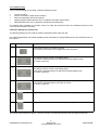
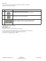
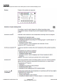
Buttons Explanation
1 Press the Info button for at least 3 seconds.
This will take you directly to the programming level "End user".
2 The display shows a number of operating pages.
Press the line selection buttons to select the required operating page.
To confirm, press OK.
3 .
The display shows a number of operating pages.
Press the line selection buttons to select the required operating line.
To confirm, press OK.
4 The display shows the value flashing.
Press the line selection buttons until value is correct.
To confirm, press OK
5 By pressing the ESC button, you come back to operating page selection.
6 By pressing the ESC button, you leave the programming level.
If no buttons are pressed for approx. 1 minute, the room unit will automatically leave the programming level.

HAMWORTHY HEATING LTD
QAA73.210
Programmable Room Unit
500001305/B
6
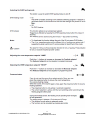
Buttons Explanation
1 Press the Info button for at least 3 seconds.
This will take you directly to the programming level "End user".
2 Press the Info button for at least 3 seconds.
This will take you to the user level selection.
3 You are now given a choice of user levels.
Press the line selection buttons to select the required user level.
To confirm, press OK. You are now on the required user level.
User levels:
The user levels only allow authorized user groups to make settings. To reach the
required user level, proceed as follows:
The following user levels are available
USR = End user
INST = Heating engineer
OEM = OEM
To reach the OEM level, the relevant code must be entered.
The table opposite shows all available settings up to the heating engineer level. However,
certain operating lines may be hidden, depending on the type of unit.
E = End user, F = Heating engineer, O = OEM

HAMWORTHY HEATING LTD
QAA73.210
Programmable Room Unit
500001305/B
7
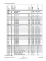
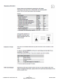
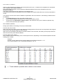
Overview of user Parameters:
Continued on next page...

HAMWORTHY HEATING LTD
QAA73.210
Programmable Room Unit
500001305/B
8
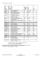
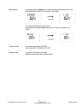
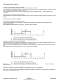
Continued from previous page...
The above table shows all available settings up to the heating engineer level. However,
certain operating lines may be hidden, depending on the type of unit.
E = End user, F = Heating engineer, O = OEM

HAMWORTHY HEATING LTD
QAA73.210
Programmable Room Unit
500001305/B
9
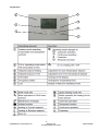
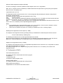
4.0 Operation
7
2
4
1
5
3
6

HAMWORTHY HEATING LTD
QAA73.210
Programmable Room Unit
500001305/B
10
4.1 Display:
Please see the previous table for the descriptions of the individual display icons.

HAMWORTHY HEATING LTD
QAA73.210
Programmable Room Unit
500001305/B
11

HAMWORTHY HEATING LTD
QAA73.210
Programmable Room Unit
500001305/B
12

HAMWORTHY HEATING LTD
QAA73.210
Programmable Room Unit
500001305/B
13

HAMWORTHY HEATING LTD
QAA73.210
Programmable Room Unit
500001305/B
4.2 Programming BMU Parameters
14
Page is loading ...
Page is loading ...
Page is loading ...
Page is loading ...
Page is loading ...
Page is loading ...
Page is loading ...
Page is loading ...
Page is loading ...
Page is loading ...
Page is loading ...
Page is loading ...
Page is loading ...
Page is loading ...
Page is loading ...
Page is loading ...
Page is loading ...
Page is loading ...
Page is loading ...
Page is loading ...
Page is loading ...
Page is loading ...
Page is loading ...
Page is loading ...
-
 1
1
-
 2
2
-
 3
3
-
 4
4
-
 5
5
-
 6
6
-
 7
7
-
 8
8
-
 9
9
-
 10
10
-
 11
11
-
 12
12
-
 13
13
-
 14
14
-
 15
15
-
 16
16
-
 17
17
-
 18
18
-
 19
19
-
 20
20
-
 21
21
-
 22
22
-
 23
23
-
 24
24
-
 25
25
-
 26
26
-
 27
27
-
 28
28
-
 29
29
-
 30
30
-
 31
31
-
 32
32
-
 33
33
-
 34
34
-
 35
35
-
 36
36
-
 37
37
-
 38
38
-
 39
39
-
 40
40
-
 41
41
-
 42
42
-
 43
43
-
 44
44


Hamworthy 500001305-B QAA73.210 Programmable Room Unit Owner's manual
- Type
- Owner's manual
Ask a question and I''ll find the answer in the document
Finding information in a document is now easier with AI
Related papers
-
Hamworthy QAA73.110 Programmable room unit for single boiler applications User manual
-
-
-
-
-
-
-
-
-
Other documents
-
Fujitsu UTW-C75XA Operating instructions
-
Baxi QAA73.110 Basic Documentation
-
Honeywell T4M Installation guide
-
elco RVA63 Zone Controller Operating instructions
-
elco ADINOx HT Installation guide
-
Salus WQ610RF Installation guide
-
Schneider Electric CCTFR6001 User guide
-
Bosch CR 50 User manual
-
Honeywell ST9520C Installation Instructions Manual
-
Schneider Electric Wiser Boiler Relay User guide