SULLAIR ShopTek ST18 Operation & Maintenance Manual
- Category
- Air compressors
- Type
- Operation & Maintenance Manual
This manual is also suitable for

ST18 & ST22
U.S.A. & Mexico
PART NUMBER:
88291013-137 R05
The information in this manual is current as of its
publication date and applies to compressors with
serial number:
37215080087
and all subsequent serial numbers.
OPERATION & MAINTENANCE MANUAL
Publication date: 11/25/2015
Copyright © 2014 – 2015 Sullair, LLC. All rights reserved.
Subject to EAR, ECCN EAR99 and related export control restrictions.
WARRANTY NOTICE
Failure to follow the instructions
and procedures in this manual,
or misuse of this equipment, will
void its warranty.
SAFETY WARNING
Users are required to read the
entire Operation & Maintenance
Manual before handling or using
the product.

Air Care Seminar Training
Sullair Air Care Seminars are courses that provide hands-on instruction for the proper operation, maintenance, and
servicing of Sullair products. Individual seminars on Stationary compressors and compressor electrical systems are
offered at regular intervals throughout the year at Sullair’s training facility located at Michigan City, Indiana.
Instruction includes training on the function and installation of Sullair service parts, troubleshooting common
faults and malfunctions, and actual equipment operation. These seminars are recommended for maintenance,
contractor maintenance, and service personnel.
For detailed course outlines, schedule, and cost information contact:
Sullair Training Department
1-888-SULLAIR or
219-879-5451 (ext. 5623)
www.sullair.com
- Or Write -
Sullair, LLC
3700 E. Michigan Blvd.
Michigan City, IN 46360
Attn: Service Training Department.
Subject to EAR, ECCN EAR99 and related export control restrictions.

Table of Contents
ST18 & ST22 (U.S.A. & Mexico) Operation & Maintenance Manual Table of Contents
88291013-137 R05
Subject to EAR, ECCN EAR99 and related export control restrictions. i
Section 1: Safety.......................................................................................................1
1.1 General....................................................................................................... 1
1.2 Personal protective equipment ................................................................... 1
1.3 Pressure release ........................................................................................ 1
1.4 Fire and explosion ...................................................................................... 2
1.5 Moving parts............................................................................................... 2
1.6 Hot surfaces, sharp edges and sharp corners............................................ 3
1.7 Toxic and irritating substances ................................................................... 3
1.8 Electrical shock........................................................................................... 4
1.9 Lifting.......................................................................................................... 4
1.10 Entrapment................................................................................................. 5
1.11 Implementation of lockout/tagout................................................................ 5
1.12 Safety warnings.......................................................................................... 6
Section 2: Description..............................................................................................9
2.1 The air compression cycle.......................................................................... 9
2.2 Air inlet system ......................................................................................... 12
2.2.1 General operation of the air inlet system .............................................................12
2.2.2 Air filter.................................................................................................................12
2.2.3 Inlet valve.............................................................................................................12
2.3 Discharge system..................................................................................... 12
2.3.1 General operation of the discharge system .........................................................12
2.3.2 Minimum pressure valve......................................................................................13
2.3.3 Automatic blowdown valve ..................................................................................13
2.3.4 Pressure relief valve ............................................................................................13
2.3.5 Aftercooler ...........................................................................................................13
2.3.6 Moisture separator...............................................................................................13
2.4 Lubrication system.................................................................................... 13
2.4.1 General description of the lubrication system......................................................13
2.4.2 Lubricating fluid....................................................................................................13
2.4.3 Fluid filter .............................................................................................................14
2.4.4 Purge oil return line..............................................................................................14
2.5 Cooling system......................................................................................... 14
2.5.1 General description of the cooling system...........................................................14
2.5.2 Ambient temperature ...........................................................................................14

Table of Contents ST18 & ST22 (U.S.A. & Mexico) Operation & Maintenance Manual
88291013-137 R05
ii Subject to EAR, ECCN EAR99 and related export control restrictions.
2.6 Fluid/air separation system.......................................................................14
2.6.1 General description of the fluid/air separation system ........................................ 14
2.6.2 Fluid/air separator tank ....................................................................................... 15
2.6.3 Fluid/air separator element ................................................................................. 15
2.7 Microprocessor control system .................................................................15
Section 3: Specifications.......................................................................................17
3.1 Machine specifications..............................................................................17
3.2 Lubricant specifications.............................................................................17
Section 4: Installation & Setup .............................................................................19
4.1 Compressor pre-installation ......................................................................19
4.2 Guidelines for lifting and moving the compressor .....................................19
4.2.1 Guidelines for moving the compressor with a forklift........................................... 19
4.2.2 Guidelines for moving the compressor with a crane ........................................... 19
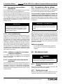
4.3 Compressor installation ............................................................................19
4.3.1 Physical installation requirements ....................................................................... 19
4.3.2 Heat rejection and ventilation requirements........................................................ 20
4.4 Connection to the air system ....................................................................20
4.5 Mechanical checks....................................................................................20
4.5.1 Checking the motor to air end coupling............................................................... 20
4.5.2 Checking the air end ........................................................................................... 20
4.5.3 Checking the compressor fluid level ................................................................... 21
4.5.4 Checking the isolation gate valve........................................................................ 21
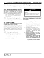
4.6 Electrical checks .......................................................................................21
4.6.1 Power supply requirements................................................................................. 21
4.6.2 Checking the motor rotation direction ................................................................. 21
Section 5: Operation..............................................................................................23
5.1 Compressor protection features................................................................23
5.1.1 Stop run-on timer ................................................................................................ 23
5.1.2 Emergency stop .................................................................................................. 23
5.2 Starting the compressor for the first time..................................................23
5.3 Starting the compressor............................................................................24
5.4 Shutting down the compressor .................................................................24
5.5 Electronic controller ..................................................................................24
5.6 High temperature shutdown......................................................................24
5.7 Motor overload protection .........................................................................24
5.8 Run-on timer .............................................................................................25

ST18 & ST22 (U.S.A. & Mexico) Operation & Maintenance Manual Table of Contents
88291013-137 R05
Subject to EAR, ECCN EAR99 and related export control restrictions. iii
Section 6: Maintenance..........................................................................................27
6.1 General..................................................................................................... 27
6.2 Daily maintenance.................................................................................... 27
6.2.1 Before starting the compressor............................................................................27
6.2.2 After starting the compressor...............................................................................27
6.3 Recommended maintenance schedule .................................................... 28
6.3.1 Service at 50 operating hours..............................................................................28
6.3.2 Service every 1000 operating hours ....................................................................28
6.3.3 Service every 2000 operating hours ....................................................................28
6.3.4 Service every 4000 operating hours (or semi-annually) ......................................28
6.3.5 Service every 10,000 hours (or yearly)................................................................28
6.3.6 Compressor fluid levels .......................................................................................29
6.4 Compressor maintenance ........................................................................ 29
6.4.1 Adding compressor fluid ......................................................................................29
6.4.2 Changing compressor fluid ..................................................................................29
6.4.3 Fluid filter maintenance........................................................................................30
6.4.4 Air filter maintenance ...........................................................................................30
6.4.5 Purge oil return line filter maintenance ................................................................31
6.4.6 Fluid/air separator maintenance ..........................................................................31
6.4.7 Minimum pressure valve maintenance ...............................................................33
6.4.8 Blowdown valve maintenance .............................................................................33
6.4.9 Solenoid valve maintenance................................................................................33
6.4.10 Pressure regulator maintenance..........................................................................33
6.4.11 Drive coupling maintenance ................................................................................34
6.5 Main motor operation and maintenance ................................................... 34
6.5.1 Main motor operation...........................................................................................35
6.5.2 Main motor maintenance and repair ....................................................................35
6.5.3 Periodic inspection of the main motor..................................................................35
6.5.4 Check and clean the windings .............................................................................36
6.6 Troubleshooting........................................................................................ 36
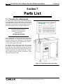
Section 7: Parts List...............................................................................................39
7.1 Procedure for ordering parts..................................................................... 39
7.2 Recommended spare parts list................................................................. 40
7.3 Motor and air end system......................................................................... 42
7.4 Air inlet system ......................................................................................... 44
7.5 Fluid piping system................................................................................... 46
7.6 Cooling fan system................................................................................... 48
7.7 Fluid/air separation system....................................................................... 50
7.8 Air discharge system ................................................................................ 52
7.9 Control system.......................................................................................... 54
7.10 Starter assembly—460/230V dual voltage ............................................... 56
7.11 Starter assembly—460V........................................................................... 58

Table of Contents ST18 & ST22 (U.S.A. & Mexico) Operation & Maintenance Manual
88291013-137 R05
iv Subject to EAR, ECCN EAR99 and related export control restrictions.
7.12 Enclosure ..................................................................................................60
7.13 Decal locations..........................................................................................62
Appendix A: System Diagrams.............................................................................65
A.1 ST18 & ST22 identification .......................................................................65
A.2 ST18 & ST22 piping and instrumentation .................................................66
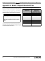
Appendix B: Metric & Imperial Nominal Sizes.....................................................68

Section 1
ST18 & ST22 (U.S.A. & Mexico) Operation & Maintenance Manual 1: Safety
88291013-137 R05
Subject to EAR, ECCN EAR99 and related export control restrictions. 1
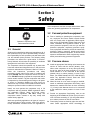
Safety
1.1 General
Sullair and its subsidiaries design and manufacture all of
their products so they can be operated safely. However,
the responsibility for safe operation rests with those who
use and maintain these products. The following safety
precautions are offered as a guide which, if conscien-
tiously followed, will minimize the possibility of accidents
throughout the useful life of this equipment.
The compressor should be operated only by those who
have been trained and delegated to do so, and who have
read and understood this Operator’s Manual. Failure to
follow the instructions, procedures and safety
precautions in this manual may result in accidents and
injuries. NEVER start the compressor unless it is safe to
do so. DO NOT attempt to operate the compressor with a
known unsafe condition. Tag the compressor and render
it inoperative by disconnecting and locking out all power
at source or otherwise disabling its prime mover so
others who may not know of the unsafe condition cannot
attempt to operate it until the condition is corrected.
Install, use and operate the compressor only in full
compliance with all pertinent OSHA regulations and/or
any applicable Federal, State, and Local codes,
standards and regulations. DO NOT modify the
compressor and/or controls in any way except with
written factory approval.
While not specifically applicable to all types of compres-
sors with all types of prime movers, most of the precau-
tionary statements contained herein are applicable to
most compressors and the concepts behind these state-
ments are generally applicable to all compressors.
1.2 Personal protective equipment
A. Prior to installing or operating the compressor, own-
ers, employers and users should become familiar
with, and comply with, all applicable OSHA regula-
tions and/or any applicable Federal, State and Local
codes, standards, and regulations relative to per-
sonal protective equipment, such as eye and face
protective equipment, respiratory protective equip-
ment, equipment intended to protect the extremities,
protective clothing, protective shields and barriers
and electrical protective equipment, as well as noise
exposure administrative and/or engineering controls
and/or personal hearing protective equipment.
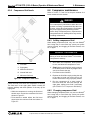
1.3 Pressure release
A. Install an appropriate flow-limiting valve between the
service air outlet and the shut-off (throttle) valve,
either at the compressor or at any other point along
the air line, when an air hose exceeding ½″ (13 mm)
inside diameter is to be connected to the shut-off
(throttle) valve, to reduce pressure in case of hose
failure, per OSHA Standard 29 CFR 1926.302(b)(7)
and/or any applicable Federal, State and Local
codes, standards and regulations.
B. When the hose is to be used to supply a manifold,
install an additional appropriate flow-limiting valve
between the manifold and each air hose exceeding
½″ (13 mm) inside diameter that is to be connected
to the manifold to reduce pressure in case of hose
failure.
C. Provide an appropriate flow-limiting valve at the
beginning of each additional 75 feet (23 m) of hose in
runs of air hose exceeding ½″ (13 mm) inside diame-
ter to reduce pressure in case of hose failure.
D. Flow-limiting valves are listed by pipe size and flow-
rated. Select appropriate valves accordingly, in
NOTE
Operator is required to read
entire instruction manual.

1: Safety ST18 & ST22 (U.S.A. & Mexico) Operation & Maintenance Manual
88291013-137 R05
2 Subject to EAR, ECCN EAR99 and related export control restrictions.
accordance with their manufacturer's recommenda-
tions.
E. DO NOT use air tools that are rated below the maxi-
mum rating of the compressor. Select air tools, air
hoses, pipes, valves, filters and other fittings accord-
ingly. DO NOT exceed manufacturer’s rated safe
operating pressures for these items.
F. Secure all hose connections by wire, chain or other
suitable retaining device to prevent tools or hose
ends from being accidentally disconnected and
expelled.
G. Open fluid filler cap only when compressor is not run-
ning and is not pressurized. Shut down the compres-
sor and bleed the receiver tank to zero internal
pressure before removing the cap.
H. Vent all internal pressure prior to opening any line, fit-
ting, hose, valve, drain plug, connection or other
component, such as filters and line oilers, and before
attempting to refill optional air line anti-icer systems
with antifreeze compound.
I. Keep personnel out of line with and away from the
discharge opening of hoses or tools or other points of
compressed air discharge.
J. DO NOT use air at pressures higher than 2.1 bar for
cleaning purposes, and then only with effective chip
guarding and personal protective equipment per
OSHA Standard 29 CFR 1910.242(b) and/or any
applicable Federal, State, and Local codes, stan-
dards and regulations.
K. DO NOT engage in horseplay with air hoses as
death or serious injury may result.
1.4 Fire and explosion
A. Clean up spills of lubricant or other combustible sub-
stances immediately, if such spills occur.
B. Shut off the compressor and allow it to cool. Then
keep sparks, flames and other sources of ignition
away and DO NOT permit smoking in the vicinity
when checking or adding lubricant or when refilling
air line anti-icer systems with antifreeze compound.
C. DO NOT permit fluids, including air line anti-icer sys-
tem antifreeze compound or fluid film, to accumulate
on, under or around acoustical material, or on any
external surfaces of the air compressor. Wipe down
using an aqueous industrial cleaner or steam clean
as required. If necessary, remove acoustical mate-
rial, clean all surfaces and then replace acoustical
material. Any acoustical material with a protective
covering that has been torn or punctured should be
replaced immediately to prevent accumulation of liq-
uids or fluid film within the material. DO NOT use
flammable solvents for cleaning purposes.
D. Disconnect and lock out all power at source prior to
attempting any repairs or cleaning of the compressor
or of the inside of the enclosure, if any.
E. Keep electrical wiring, including all terminals and
pressure connectors in good condition. Replace any
wiring that has cracked, cut, abraded or otherwise
degraded insulation, or terminals that are worn, dis-
colored or corroded. Keep all terminals and pressure
connectors clean and tight.
F. Keep grounded and/or conductive objects such as
tools away from exposed live electrical parts such as
terminals to avoid arcing which might serve as a
source of ignition.
G. Remove any acoustical material or other material
that may be damaged by heat or that may support
combustion and is in close proximity, prior to attempt-
ing weld repairs.
H. Keep suitable fully charged Class BC or ABC fire
extinguisher or extinguishers nearby when servicing
and operating the compressor.
I. Keep oily rags, trash, leaves, litter or other combusti-
bles out of and away from the compressor.
J. DO NOT operate the compressor without proper flow
of cooling air or water or with inadequate flow of lubri-
cant or with degraded lubricant.
K. DO NOT attempt to operate the compressor in any
classification of hazardous environment unless the
compressor has been specially designed and manu-
factured for that duty.
1.5 Moving parts
A. Keep hands, arms and other parts of the body and
clothing away from couplings, belts, pulleys, fans and
other moving parts.
B. DO NOT attempt to operate the compressor with the
fan, coupling or other guards removed.
C. Wear snug-fitting clothing and confine long hair when
working around this compressor, especially when
exposed to hot or moving parts.
D. Keep access doors, if any, closed except when mak-
ing repairs or adjustments.

ST18 & ST22 (U.S.A. & Mexico) Operation & Maintenance Manual 1: Safety
88291013-137 R05
Subject to EAR, ECCN EAR99 and related export control restrictions. 3
E. Make sure all personnel are out of and/or clear of the
compressor prior to attempting to start or operate it.
F. Disconnect and lock out all power at source and ver-
ify at the compressor that all circuits are de-energized
to minimize the possibility of accidental start-up, or
operation, prior to attempting repairs or adjustments.
This is especially important when compressors are
remotely controlled.
G. Keep hands, feet, floors, controls and walking sur-
faces clean and free of fluid, water or other liquids to
minimize the possibility of slips and falls.
1.6 Hot surfaces, sharp edges and
sharp corners
A. Avoid bodily contact with hot fluid, hot coolant, hot
surfaces and sharp edges and corners.
B. Keep all parts of the body away from all points of air
discharge.
C. Wear personal protective equipment including gloves
and head covering when working in, on or around the
compressor.
D. Keep a first aid kit handy. Seek medical assistance
promptly in case of injury. DO NOT ignore small cuts
and burns as they may lead to infection
1.7 Toxic and irritating substances
A. DO NOT use air from this compressor for respiration
(breathing) except in full compliance with OSHA
Standards 29 CFR 1910 and/or any applicable Fed-
eral, State or Local codes or regulations.
B. DO NOT use air line anti-icer systems in air lines
supplying respirators or other breathing air utilization
equipment and DO NOT discharge air from these
systems into unventilated or other confined areas.
C. Operate the compressor only in open or adequately
ventilated areas.
D. Locate the compressor or provide a remote inlet so
that it is not likely to ingest exhaust fumes or other
toxic, noxious or corrosive fumes or substances.
E. Coolants and lubricants used in this compressor are
typical of the industry. Care should be taken to avoid
accidental ingestion and/or skin contact. In the event
of ingestion, seek medical treatment promptly. Wash
with soap and water in the event of skin contact.
Consult Material Safety Data Sheet for information
pertaining to fluid of fill.
F. Wear goggles or a full face shield when adding anti-
freeze compound to air line anti-icer systems.
G. If air line anti-icer system antifreeze compound
enters the eyes or if fumes irritate the eyes, they
should be washed with large quantities of clean
water for fifteen minutes. A physician, preferably an
eye specialist, should be contacted immediately.
H. DO NOT store air line anti-icer system antifreeze
compound in confined areas.
I. The antifreeze compound used in air line antifreeze
systems contains methanol and is toxic, harmful or
fatal if swallowed. Avoid contact with the skin or eyes
and avoid breathing the fumes. If swallowed, induce
vomiting by administering a tablespoon of salt, in
each glass of clean, warm water until vomit is clear,
then administer two teaspoons of baking soda in a
glass of clean water. Have patient lay down and
DANGER
Death or serious injury can result from inhaling
compressed air without using proper safety
equipment. See OSHA standards and/or any
applicable Federal, State, and Local codes, stan-
dards and regulations on safety equipment.

1: Safety ST18 & ST22 (U.S.A. & Mexico) Operation & Maintenance Manual
88291013-137 R05
4 Subject to EAR, ECCN EAR99 and related export control restrictions.
cover eyes to exclude light. Call a physician immedi-
ately.
1.8 Electrical shock
A. This compressor should be installed and maintained
in full compliance with all applicable Federal, State
and Local codes, standards and regulations, includ-
ing those of the National Electrical Code, and also
including those relative to equipment grounding con-
ductors, and only by personnel that are trained, qual-
ified and delegated to do so.
B. Keep all parts of the body and any hand-held tools or
other conductive objects away from exposed live
parts of electrical system. Maintain dry footing, stand
on insulating surfaces and DO NOT contact any
other portion of the compressor when making adjust-
ments or repairs to exposed live parts of the electrical
system. Make all such adjustments or repairs with
one hand only, so as to minimize the possibility of
creating a current path through the heart.
C. Attempt repairs in clean, dry and well lighted and
ventilated areas only.
D. DO NOT leave the compressor unattended with open
electrical enclosures. If necessary to do so, then discon-
nect, lock out and tag all power at source so others will
not inadvertently restore power.
E. Disconnect, lock out, and tag all power at source
prior to attempting repairs or adjustments to rotating
machinery and prior to handling any ungrounded
conductors.
1.9 Lifting
A. If the compressor is provided with a lifting bail, then
lift by the bail provided. If no bail is provided, then lift
by sling. Compressors to be air-lifted by helicopter
must not be supported by the lifting bail but by slings
instead. In any event, lift and/or handle only in full
compliance with OSHA standards 29 CFR 1910 sub-
part N and/or any applicable Federal, State, and
Local codes, standards and regulations.
B. Inspect points of attachment for cracked welds and
for cracked, bent, corroded or otherwise degraded
members and for loose bolts or nuts prior to lifting.
C. Make sure entire lifting, rigging and supporting struc-
ture has been inspected, is in good condition and has
a rated capacity of at least the weight of the com-
pressor. If you are unsure of the weight, then weigh
compressor before lifting.
D. Make sure lifting hook has a functional safety latch or
equivalent, and is fully engaged and latched on the
bail or slings.
E. Use guide ropes or equivalent to prevent twisting or
swinging of the compressor once it has been lifted
clear of the ground.
F. DO NOT attempt to lift in high winds.
G. Keep all personnel out from under and away from the
compressor whenever it is suspended.
H. Lift compressor no higher than necessary.
I. Keep lift operator in constant attendance whenever
compressor is suspended.
DANGER
All field equipment must be tested for electro-
static fields prior to servicing or making contact
with the machine using the following or equiva-
lent test equipment:
• 90 – 600 VAC: Volt detector such as
Fluke Model 1AC-A
• 600 – 7000 VAC: Voltage detector such
as Fluke Networks Model C9970
It is the responsibility of each organization to
provide/arrange training for all their associates
expected to test for electrostatic fields.

ST18 & ST22 (U.S.A. & Mexico) Operation & Maintenance Manual 1: Safety
88291013-137 R05
Subject to EAR, ECCN EAR99 and related export control restrictions. 5
J. Set compressor down only on a level surface capa-
ble of safely supporting at least its weight and its
loading unit.
K. When moving the compressor by forklift truck, utilize
fork pockets if provided. Otherwise, utilize pallet if
provided. If neither fork pockets or pallet are pro-
vided, then make sure compressor is secure and well
balanced on forks before attempting to raise or trans-
port it any significant distance.
L. Make sure forklift truck forks are fully engaged and
tipped back prior to lifting or transporting the com-
pressor.
M. Forklift no higher than necessary to clear obstacles
at floor level and transport and corner at minimum
practical speeds.
N. Make sure pallet-mounted compressors are firmly
bolted or otherwise secured to the pallet prior to
attempting to forklift or transport them. NEVER
attempt to forklift a compressor that is not secured to
its pallet, as uneven floors or sudden stops may
cause the compressor to tumble off, possibly causing
serious injury or property damage in the process.
1.10 Entrapment
A. If the compressor enclosure, if any, is large enough
to hold a man and if it is necessary to enter it to per-
form service adjustments, inform other personnel
before doing so, or else secure and tag the access
door in the open position to avoid the possibility of
others closing and possibly latching the door with
personnel inside.
B. Make sure all personnel are out of compressor
before closing and latching enclosure doors.
1.11 Implementation of lockout/tagout
The energy control procedure defines actions necessary
to lockout a power source of any machine to be repaired,
serviced or set-up, where unexpected motion, or an
electrical or other energy source, would cause personal
injury or equipment damage. The power source on any
machine shall be locked out by each employee doing the
work except when motion is necessary during setup,
adjustment or trouble-shooting.
A. The established procedures for the application of
energy control shall cover the following elements and
actions and shall be initiated only by Authorized Per-
sons and done in the following sequence:
1. Review the equipment or machine to be
locked and tagged out.
2. Alert operator and supervisor of which
machine is to be worked on, and that power
and utilities will be turned off.
3. Check to make certain no one is operating
the machine before turning off the power.
4. Turn off the equipment using normal shut-
down procedure.
5. Disconnect the energy sources:
a. Air and hydraulic lines should be bled,
drained and cleaned out. There should
be no pressure in these lines or in the
reservoir tanks. Lockout or tag lines or
valves.
b. Any mechanism under tension or pres-
sure, such as springs, should be
released and locked out or tagged.
c. Block any load or machine part prior to
working under it.
d. Electrical circuits should be checked with
calibrated electrical testing equipment
and stored energy and electrical capaci-
tors should be safely discharged.
6. Lockout and/or Tagout each energy source
using the proper energy isolating devices
and tags. Place lockout hasp and padlock or
tag at the point of power disconnect where
lockout is required by each person perform-
ing work. Each person shall be provided with
their own padlock and have possession of
the only key. If more than one person is
working on a machine each person shall affix
personal lock and tag using a multi-lock
device.
7. Tagout devices shall be used only when
power sources are not capable of being
locked out by use of padlocks and lockout
hasp devices. The name of the person affix-
ing tag to power source must be on tag along
with date tag was placed on power source.
8. Release stored energy and bring the equip-
ment to a “zero mechanical state”.
9. Verify Isolation: Before work is started, test
equipment to ensure power is disconnected.
B. General Security
1. The lock shall be removed by the “Autho-
rized” person who put the lock on the
energy-isolating device. No one other than
the person/persons placing padlocks and

1: Safety ST18 & ST22 (U.S.A. & Mexico) Operation & Maintenance Manual
88291013-137 R05
6 Subject to EAR, ECCN EAR99 and related export control restrictions.
lockout hasps on power shall remove pad-
lock and lockout hasps and restore power.
However, when the authorized person who
applied the lock is unavailable to remove it
his/her Supervisor may remove padlock/pad-
locks and lockout hasps and restore power
only if it is first:
a. verified that no person will be exposed to
danger.
b. verified that the “Authorized” person who
applied the device is not in the facility.
c. noted that all reasonable efforts to con-
tact the “Authorized” person have been
made to inform him or her that the lock-
out or tagout device has been removed.
d. ensured that the “Authorized” person is
notified of lock removal before returning
to work.
2. Tagout System—Tags are warning devices
affixed at points of power disconnect and are
not to be removed by anyone other that the
person placing tag on power lockout. Tags
shall never be by-passed, ignored, or other-
wise defeated.
1.12 Safety warnings
The following special instructions apply to VSD packages
provided with electronic adjustable speed motor drives.
These cautions that apply to VSD operation.
WARNING
Ground the unit following the instructions in this
manual. Ungrounded units may cause electric
shock and/or fire. The variable speed drive has a
large capacitive leakage current during opera-
tion, which can cause enclosure parts to be
above ground potential. Proper grounding, as
described in this manual, is required. Failure to
observe this precaution could result in death or
severe injury.
WARNING
Before applying power to the variable speed
drive, make sure that the front and cable covers
are closed and fastened to prevent exposure to
potential electrical fault conditions. Failure to
observe this precaution could result in death or
severe injury.
WARNING
Refer all drive service to trained technicians.
This equipment should be installed, adjusted,
and serviced by qualified electrical maintenance
personnel familiar with the construction and
operation of this type of equipment and the haz-
ards involved and in accordance with published
service manuals. Failure to observe this precau-
tion could result in death or severe injury.
WARNING
Line terminals (L1, L2, L3), motor terminals (U,
V, W) and the DC link/brake resistor terminals (-/
+) are live when the drive is connected to power,
even if the motor is not running. Contact with
this voltage is extremely dangerous and may
cause death or severe injury.

ST18 & ST22 (U.S.A. & Mexico) Operation & Maintenance Manual 1: Safety
88291013-137 R05
Subject to EAR, ECCN EAR99 and related export control restrictions. 7
WARNING
Before opening the variable speed drive covers:
• Disconnect all power to the variable
speed drive.
• Wait a minimum of 5 (five) minutes
after all the lights on the keypad are
off. This allows time for the DC bus
capacitors to discharge.
• A hazard voltage may still remain in
the DC bus capacitors even if the
power has been turned off. Confirm
that the capacitors have fully dis-
charged by measuring their voltage
using a multimeter set to measure DC
voltage. Failure to follow the above
precautions may cause death or
severe injury.
CAUTION
Do not perform any megger or voltage withstand
tests on any part of the variable speed drive or
its components. Improper testing may result in
damage. Prior to any tests or measurements of
the motor or the motor cable, disconnect the
motor cable at the variable speed drive output
terminals (U, VW) to avoid damaging the vari-
able speed drive during motor or cable testing.
CAUTION
Do not touch any components on the circuit
boards. Static voltage discharge may damage
the components.
CAUTION
Install the variable speed drive in a well venti-
lated room that is not subject to temperature
extremes, high humidity, or condensation, and
avoid locations that are directly exposed to sun-
light, or have high concentrations of dust, corro-
sive gas, explosive gas, inflammable gas,
grinding fluid mist, etc. Improper installation may
result in a fire hazard.
CAUTION
Make sure that no power correction capacitors
are connected to the variable speed drive output
or the motor terminals to prevent variable speed
drive malfunction and potential damage.
CAUTION
Make sure that the variable speed drive output
terminals (U, V, W) are not connected to the util-
ity line power as severe damage to the VSD may
occur.
NOTE
Interior electrical wiring is performed at the fac-
tory. Required customer wiring is minimal, but
should be done by a qualified electrician in com-
pliance with OSHA, National Electrical Code,
and/or any other applicable State, Federal, and
local electrical codes concerning isolation
switches, fused disconnects, etc. Sullair pro-
vides a wiring diagram for use by the installer.
NOTE
Customer must provide electrical supply power
disconnect within sight of machine.

1: Safety ST18 & ST22 (U.S.A. & Mexico) Operation & Maintenance Manual
Notes:
88291013-137 R05
8 Subject to EAR, ECCN EAR99 and related export control restrictions.

Section 2
ST18 & ST22 (U.S.A. & Mexico) Operation & Maintenance Manual 2: Description
88291013-137 R05
Subject to EAR, ECCN EAR99 and related export control restrictions. 9
Description
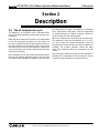
2.1 The air compression cycle
The ShopTek™ air compressor uses a lubricated rotary
screw air end and supporting components to create com-
pressed air.
When the rotors inside the air end turn, they draw outside
air into the compressor through the air inlet system. As
the rotors compress this air from atmospheric pressure to
the target pressure, the lubrication system injects fluid
into the air end to cool the compressed air, lubricate the
rotors and bearings, and create a seal between the rotors
and the air end casing.
After leaving the air end, the compressed air/fluid mixture
flows into the fluid/air separation system. First, the fluid/
air separator tank separates the majority of the fluid from
the compressed air using a combination of centrifugal
force, impingement, and gravity. Then the compressed
air passes through the fluid/air separator element to
remove almost all of the remaining fluid.
Next, the compressed air flows through the aftercooler.
The aftercooler cools the compressed air to 8 – 12°C
(14 – 22°F) above the ambient temperature. The com-
pressed air then flows through the moisture separator (if
installed). The moisture separator collects the water
vapor that condensed when the compressed air was
cooled.
After leaving the aftercooler (or the moisture separator, if
installed), the compressed air flows through the service
connector of the compressor for downstream use.

2: Description ST18 & ST22 (U.S.A. & Mexico) Operation & Maintenance Manual
88291013-137 R05
10 Subject to EAR, ECCN EAR99 and related export control restrictions.
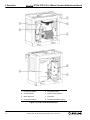
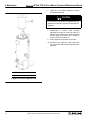
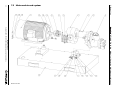
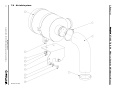
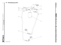
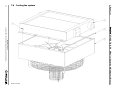
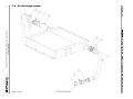
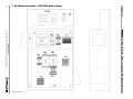
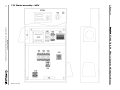
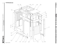
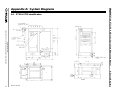
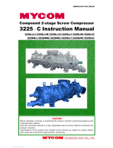
Figure 2-1: ST18 & ST22 machine layout
1. Fluid piping system 5. Discharge system
2. Air inlet system 6. Electric control system
3. Motor & air end 7. Enclosure
4. Cooling fan system 8. Fluid/air separation system

ST18 & ST22 (U.S.A. & Mexico) Operation & Maintenance Manual 2: Description
88291013-137 R05
Subject to EAR, ECCN EAR99 and related export control restrictions. 11
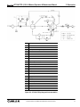
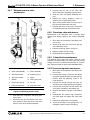
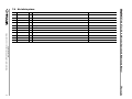
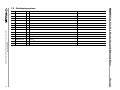
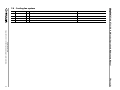
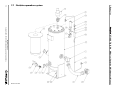
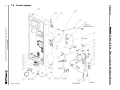
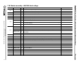
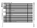
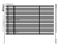
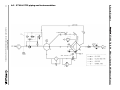
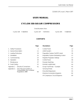
Figure 2-2: ST18 & ST22 piping and instrumentation
Key Description
1Air filter
2 Inlet valve
3 Capacity control integrated system
4Oil cooler
5 Pressure switch
6 Indicator
7 Aftercooler
8 Minimum pressure valve
9 Single-stage fluid/air separator element
10 Strainer
11 Moisture separator
12 Pressure sensor
13 Temperature sensor
14 Compressor air end
15 Relief valve
16 Fluid/air separator tank
17 Sight glass
18 Oil plug
19 Fluid filter
20 Fluid filter pressure difference indicator
21 Strainer
22 Sight glass
23 Orifice
24 Thermal valve

2: Description ST18 & ST22 (U.S.A. & Mexico) Operation & Maintenance Manual
88291013-137 R05
12 Subject to EAR, ECCN EAR99 and related export control restrictions.
2.2 Air inlet system
The air inlet system provides air for the compressor to
pressurize. The primary components of the air inlet sys-
tem are the air filter, inlet valve, and compressor air end.
2.2.1 General operation of the air inlet
system
The air end draws outside air through the air filter and
inlet valve into the air end compression chamber. Inside
the compression chamber, a male and female rotor pair
revolve at high speed, compressing the air and increas-
ing its pressure. When the compressed air/fluid mixture
reaches the end of the compression chamber, the mix-
ture flows through the air end discharge port into the
fluid/air separator.
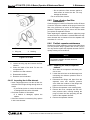
2.2.2 Air filter
The air filter removes particulates from the intake air, pro-
viding clean air to the compressor. If these particulates
were not removed, they could wear down rotor surfaces
and contaminate the compressor fluid.
2.2.2.1 Air filter element
Because the air filter element traps the particulates it fil-
ters from the air on its surface, the air filter element must
be changed periodically to maintain the air filter’s effec-
tiveness.
Additional information
• For the recommended air filter maintenance
schedule, see Section 6.3: Recommended
maintenance schedule on page 28.
• For instructions on how to change the air filter
element, see Section 6.4.4: Air filter mainte-
nance on page 30.
2.2.3 Inlet valve
The inlet valve controls intake air volume using a modula-
tion control system.
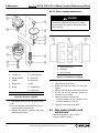
2.2.3.1 Inlet modulation
To minimize the number of starts and stops the compres-
sor makes, the inlet modulation system automatically
adjusts the size of the inlet valve opening to match air
demand. The primary components of the inlet modulation
system are the solenoid valve, inlet valve, blowdown
valve, and control line.
When air demand is equal to or greater than the com-
pressors rating, the compressor will run at full load. The
solenoid valve is energized, closing the control line.
Because the control is not in use, the inlet valve of the air
end is fully open.
When air demand is lower than the compressor rating,
discharge pressure builds up slowly. Once the discharge
pressure reaches the unload setting of the controller, the
compressor will switch to unload mode. The solenoid
valve is de-energized, opening the control line. Because
the control line is in use and the discharge pressure is
high, the control line closes the inlet valve. At the same
time, the blowdown valve opens to release the pressure
in the fluid/air separator tank until the pressure stabilizes
at 15 – 25 psi.
Now the compressor will run with no load for a preset
time. Once the preset time is reached, the compressor
will stop. However, if the discharge pressure drops to the
load setting of the controller before the preset time is
reached, the compressor re-enters load mode. The sole-
noid valve is energized, closing the control line. Because
the control is not in use, the inlet valve of the air end is
fully open.
2.3 Discharge system
The discharge system pushes air from the compressor
air end to the service connector. The primary compo-
nents of the discharge system are the compressor air
end, fluid/air separator, minimum pressure valve, pres-
sure relief valve, automatic blowdown valve, aftercooler,
moisture separator (optional), and service connector.
2.3.1 General operation of the discharge
system
The compressed air/fluid mixture flows through the air
end discharge port into the fluid/air separator tank and
separator element. The separator tank and element
remove fluid from the air.
The compressed air then flows through the minimum
pressure valve, followed by the aftercooler, then the
moisture separator (if installed). Once the air is cooled
and the moisture removed (if the moisture separator is
installed), the air flows to the service connector for down-
stream use.
To lower the frequency of the compressor’s load/unload
cycles and extend the life of the compressor, Sullair rec-
WARRANTY NOTICE
Failure to follow the air filter maintenance sched-
ule or use Sullair genuine air filter elements can
cause early contamination of the compressor
fluid and the fluid/air separator element and may
void your warranty.

ST18 & ST22 (U.S.A. & Mexico) Operation & Maintenance Manual 2: Description
88291013-137 R05
Subject to EAR, ECCN EAR99 and related export control restrictions. 13
ommends installing a wet air receiver after the service
connector.
Additional information
• For the size of the service connector, see Sec-
tion 3.1: Machine specifications on page 17.
2.3.2 Minimum pressure valve
The minimum pressure valve on the top cover of the fluid/
air separator ensures lubricant flow during both normal
operation and start-up by keeping pressure in the fluid/air
separator above 340 kPa (49.3 psi).
When pressure in the fluid/air separator is above 340 kPa
(49.3 psi) and higher than the downstream pipeline pres-
sure, the minimum pressure valve will be opened. Other-
wise, the minimum pressure valve will be closed to
maintain minimum tank pressure.
The minimum pressure valve also functions as a check
(non-return) valve, preventing compressed air down-
stream of the separator from flowing back into the sepa-
rator and air end during compressor blowdown.
2.3.3 Automatic blowdown valve
When the compressor is unloading or stopping, the blow-
down valve in the control line automatically opens to
release pressure. The blowdown valve routes the air to
the air inlet pipe (after the air filter) to prevent a com-
pressed air/fluid mixture from venting into the atmo-
sphere.
2.3.4 Pressure relief valve
To prevent damage to the fluid/air separator and other
compressor components the pressure relief valve located
on the fluid/air separator tank will open when the pres-
sure in the separator tank exceeds the pressure relief
valve setpoint.
Under normal operating conditions, the over pressure
stop switch will shut down the compressor before the
pressure relief valve setpoint is reached (see Section 3.1:
Machine specifications on page 17). However, the pres-
sure relief valve serves as an additional mechanical safe-
guard.
2.3.5 Aftercooler
The aftercooler cools the compressed air to 8 – 12°C
(14 – 22°F) above the ambient temperature. This cooling
causes water vapor to condense, which creates moisture
in the compressed air stream.
2.3.6 Moisture separator
The moisture separator removes the moisture from the
compressed air stream. Moisture collected by the mois-
ture separator can then be safely disposed of according
to local regulations.
2.4 Lubrication system
The lubrication system cools the compressor; lubricates
the rotors, bearings, and gears; and seals the air end
against leaks. The primary components of the lubrication
system are the compressor air end, fluid/air separator,
thermal valve, aftercooler, fluid filter, and interconnecting
piping.
2.4.1 General description of the lubrication
system
Fluid is injected into the air end compression chamber,
where it is compressed along with the intake air. The
compressed air/fluid mixture then flows into the fluid/air
separation system, which separates the fluid from the air
and collects the fluid for re-use. Depending on the fluid
temperature, the thermal valve routes none, some, or all
of the fluid to the aftercooler for cooling. Fluid that has
passed through the aftercooler, or that was not routed to
the aftercooler, flows through the fluid filter into the air
end to restart the lubrication cycle.
2.4.2 Lubricating fluid
The lubricating fluid provides three benefits.
•Cooling. The compressor fluid acts as a cool-
ant, absorbing the large amount of heat gener-
ated during compression.
•Lubricating. The compressor fluid forms a
layer between the rotors, preventing the male
and female rotors from making direct contact
and minimizing the surface wear of the rotors.
The compressor fluid also lubricates the bear-
ings and gears.
•Sealing. Compressor fluid with sufficient vis-
cosity can fill the gaps between rotors and
between the rotors and the casing. This
reduces air lost through leakage and increases
the efficiency of the compressor.
NOTE
The moisture separator ships loose for the cus-
tomer to install if needed for their installation. It is
not installed by the factory.

2: Description ST18 & ST22 (U.S.A. & Mexico) Operation & Maintenance Manual
88291013-137 R05
14 Subject to EAR, ECCN EAR99 and related export control restrictions.
Additional information
• For the viscosity required for the compressor
fluid to act as a sealant, see Section 3.2: Lubri-
cant specifications on page 17.
2.4.3 Fluid filter
The fluid filter collects any impurities in the compressor
fluid and ensures that only clean fluid enters the air end
compression chamber and internal lubrication feeds. If
these impurities in the fluid were not removed, they would
cause wear on the rotor and gear surfaces and bearings
and shorten the life of compressor.
2.4.3.1 Fluid filter element
Because the fluid filter element collects impurities on its
surface, the fluid filter element must be replaced regularly
to ensure good fluid circulation for proper lubrication and
cooling.
Additional information
• For the recommended fluid filter maintenance
schedule, see Section 6.3: Recommended
maintenance schedule on page 28.
• For instructions on how to change the fluid filter
element, see Section 6.4.3: Fluid filter mainte-
nance on page 30.
2.4.4 Purge oil return line
The purge oil return line located on the cover of the fluid/
air separator passes the compressor fluid collected by
the fluid/air separator element through the purge line fil-
ter, then returns the clean fluid to the compressor air end.
A small orifice in the purge oil return line limits return air
flow, minimizing the loss of compressed air. A sight glass
located in the purge line allows an operator to observe
the amount of fluid returning from the separator element.
2.5 Cooling system
The cooling system maintains a proper operating temper-
ature for the compressor.
2.5.1 General description of the cooling
system
Suction created by an axial flow cooling fan pulls cooling
air through louvers on both sides of the compressor. This
cooling air draws heat from the aftercooler before flowing
out of the machine.
2.5.2 Ambient temperature
Sullair ShopTek™ compressors are designed to operate
in ambient temperatures between 4°C and 40°C (40°F
and 104°F), measured at the cooling air inlet. If you need
to operate the compressor in a temperature outside this
range, contact your Sullair representative.
2.5.2.1 High ambient temperature and
overheating
If the ambient temperature is above 40°C (104°F), the air
drawn into the compressor may be too hot to adequately
cool the compressor fluid or the electric motor when the
compressor is operating at full load. If the compressor
load is less than 100%, operating the compressor in
higher ambient temperatures may be possible.
Regardless of the ambient temperature, the maximum
recommended operating temperature is 108°C (226°F).
2.6 Fluid/air separation system
The fluid/air separator system removes the fluid from the
compressed air stream. The primary components of the
fluid/air separation system are the fluid/air separator tank
and fluid/air separator element.
2.6.1 General description of the fluid/air
separation system
The compressed air/fluid mixture from the air end flows
into the fluid/air separator and strikes the wall of the sep-
arator tank, causing large drops of fluid to form because
of the lower air speed. Most of these fluid drops attach to
the wall of the tank, and gravity causes the drops to col-
lect at the bottom of the tank. The thermal valve then
routes this collected fluid back to the air end through the
aftercooler (if necessary) and the filter.
CAUTION
Continuously exceeding the maximum operating
temperature will damage the compressor.
CAUTION
In the event of a high operating temperature
shutdown fault, do not attempt to restart the
compressor without first finding and correcting
the underlying cause. Contact your Sullair repre-
sentative for assistance.
Page is loading ...
Page is loading ...
Page is loading ...
Page is loading ...
Page is loading ...
Page is loading ...
Page is loading ...
Page is loading ...
Page is loading ...
Page is loading ...
Page is loading ...
Page is loading ...
Page is loading ...
Page is loading ...
Page is loading ...
Page is loading ...
Page is loading ...
Page is loading ...
Page is loading ...
Page is loading ...
Page is loading ...
Page is loading ...
Page is loading ...
Page is loading ...
Page is loading ...
Page is loading ...
Page is loading ...
Page is loading ...
Page is loading ...
Page is loading ...
Page is loading ...
Page is loading ...
Page is loading ...
Page is loading ...
Page is loading ...
Page is loading ...
Page is loading ...
Page is loading ...
Page is loading ...
Page is loading ...
Page is loading ...
Page is loading ...
Page is loading ...
Page is loading ...
Page is loading ...
Page is loading ...
Page is loading ...
Page is loading ...
Page is loading ...
Page is loading ...
Page is loading ...
Page is loading ...
Page is loading ...
Page is loading ...
Page is loading ...
Page is loading ...
-
 1
1
-
 2
2
-
 3
3
-
 4
4
-
 5
5
-
 6
6
-
 7
7
-
 8
8
-
 9
9
-
 10
10
-
 11
11
-
 12
12
-
 13
13
-
 14
14
-
 15
15
-
 16
16
-
 17
17
-
 18
18
-
 19
19
-
 20
20
-
 21
21
-
 22
22
-
 23
23
-
 24
24
-
 25
25
-
 26
26
-
 27
27
-
 28
28
-
 29
29
-
 30
30
-
 31
31
-
 32
32
-
 33
33
-
 34
34
-
 35
35
-
 36
36
-
 37
37
-
 38
38
-
 39
39
-
 40
40
-
 41
41
-
 42
42
-
 43
43
-
 44
44
-
 45
45
-
 46
46
-
 47
47
-
 48
48
-
 49
49
-
 50
50
-
 51
51
-
 52
52
-
 53
53
-
 54
54
-
 55
55
-
 56
56
-
 57
57
-
 58
58
-
 59
59
-
 60
60
-
 61
61
-
 62
62
-
 63
63
-
 64
64
-
 65
65
-
 66
66
-
 67
67
-
 68
68
-
 69
69
-
 70
70
-
 71
71
-
 72
72
-
 73
73
-
 74
74
-
 75
75
-
 76
76


SULLAIR ShopTek ST18 Operation & Maintenance Manual
- Category
- Air compressors
- Type
- Operation & Maintenance Manual
- This manual is also suitable for
Ask a question and I''ll find the answer in the document
Finding information in a document is now easier with AI
Related papers
Other documents
-
 Thermal Transfer AB Series Datasheet
-
COMPRESSED AIR USA Air Compressor Oil Operating instructions
-
 Quincy QGV-20 User manual
-
 Auto Crane AC40 Piston Service And Maintenance User Manual
-
 Glenko Senator ZS150T User manual
-
Clarke SHHH 2 Operating instructions
-
 Deutsch QR-30-22P Assembly Instructions
-
Amtrol Air Separator Installation and Operation Instructions
-
 mycom 3225MLC User manual
-
 CompAir BroomWade Cyclon 337 User manual


