Page is loading ...

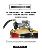
EZ-8 & EZ-8 METHANOL FUEL PUMP
OWNER’S MANUAL
DO NOT RETURN THIS
PRODUCT TO THE STORE!
Please contact Great Plains Industries, Inc.
before returning any product. If you are
missing parts, or experience problems with
your installation, contact our
Customer Support Department.
We will be happy to assist you.
800-835-0113,
316-686-7361
or
email:
gpisales@gplains
.
com
Check out the Great Plains Industries, Inc. YouTube
channel to see Installation and Troubleshooting
videos for the EZ-8 Fuel Transfer Pump.
TABLE OF CONTENTS
To the owner...
Congratulations on receiving your GPI
®
Fuel Transfer
Pump. We are pleased to provide you with a system
designed to give you maximum reliability and efficiency.
Your fuel pump is engineered, tested, and approved
for use with gasoline blends, diesel fuel blends and
kerosene (and methanol for the EZ-8 Methanol model).
Please take all due precautions when handling these
flammable liquids. Your safety is important to us.
Also, to assure the longest possible service life,
it is important that you follow the operation and
maintenance procedures outlined in this manual. We
are proud to provide you with a quality product and
dedicated support. Our commitment, together with
your conscientious use, will ensure years of safe,
dependable service from your fuel pump.
General
Information
���������������������������������������������
2 Safety
Instructions
���������������������������������������������� 2 Parts &
Service
���������������������������������������������������� 3
Tools
Needed
������������������������������������������������������� 3
Contents
Checklist
���������������������������������������������� 3
Installa-
tion
�����������������������������������������������������������
4
Operation �������������������������������������������������������������
6
Maintenance ��������������������������������������������������������
6
Troubleshooting ���������������������������������������������������
6
Specifications
������������������������������������������������������
8
Illustrated
Parts
List
-
EZ-8
/
EZ-8
Methanol
�����
9
W
arran-
ty
�������������������������������������������������������������
12
Victor Lukic, President
Great Plains Industries, Inc.
921803-01 Rev G
10/20

GENERAL INFORMATION
The purpose of this manual is to assist you in-
stalling, operating, and maintaining your GPI EZ-8
or EZ-8 Methanol 12-volt DC pump, with manual
nozzle.
NOTE: This pump is not intended for use
with an automatic nozzle.
An automatic bypass valve inside the pump pre-
vents pressure build up when the pump is on with
the nozzle closed. To avoid motor damage, do not
run the pump more than 5 minutes with the nozzle
closed.
The rated duty cycle of this pump is 15 minutes
ON and 30 minutes OFF. Allow the pump to cool
for 30 minutes.
The EZ-8 is designed for use with gasoline (up to
15% alcohol blends such as E15), diesel fuel (up
to 20% biodiesel blends such as B20) and kero-
sene only. Do not use this pump for dispensing
any fluids other than those for which it was de-
signed. Doing so may damage pump components
and will void the warranty.
The EZ-8 Methanol pump is specifically designed
for use with methanol and ethanol. The pump is
also compatible with gasoline (E15), diesel fuel
(B20), and kerosene. Do not use this pump for
dispensing any fluids other than those for which it
was designed. Doing so may damage pump com-
ponents and will void the warranty.
SAFETY INSTRUCTIONS
Observe all safety precautions concerning safe
handling of petroleum fuels.
To ensure safe operation, all fuel transfer systems
must be properly grounded. Proper grounding
means a continuous metal-to-metal contact from
one component to the next, including tank, tank
adapter, pump, meter, filter, hose, and nozzle.
Care should be taken to ensure proper grounding
during initial installation and after any service or
repair procedures. For your safety, please take a
moment to review the warnings below.
•
To prevent physical injury, observe precautions
against fire or explosion when dispensing fuel.
Do not operate the system in the presence of
any source of ignition including running or hot
engines, lighted cigarettes, or gas or electric
heaters.
Observe precautions against electrical shock
when operating the system. Serious or fatal
shock can result from operating electrical
equipment in damp or wet locations.
Inspect external pump wiring regularly to
make sure it is correctly attached to the bat-
tery. To avoid electrical shock, use extra care
when connecting the pump to power.
Avoid prolonged skin contact with petroleum
fuels. Use protective goggles, gloves, and
aprons in case of splashing or spills. Change
saturated clothing and wash skin promptly
with soap and water.
Observe precautions against electrical shock
when servicing the pump. Always disconnect
power before repairing or servicing.
Never apply electrical power to the system
when any of the coverplates are removed.
Ensure that all operators who use this pump
are educated on its function and precau-
tions. All operators must have convenient
access to adequate instructions concerning
safe operating and maintenance procedures
contained in this manual.
Ensure all fluid connections to and from the
pump are properly sealed and tightened with
appropriate thread tape, gaskets, or o-rings.
If using solvent to clean pump components
or tank, observe the solvent manufacturer’s
recommendations for safe use and disposal.
•
•
•
•
This pump is designed to operate on a typical 12-
volt DC automotive electrical system. The pump is
designed to operate with 12-volts DC at the motor
leads, and the ratings are determined at that volt-
age. Performance may vary due to length of power
cord, battery condition, or output from vehicle
charging system affecting system voltage.
Do not leave the system running without fluids.
“Dry running” can damage the pump. If the sys-
tem fails to deliver fuel after 15 to 20 seconds, turn
the system off and refer to the Troubleshoot- ing
Section.
Do not completely empty the fuel tank, as contami-
nants from the bottom of the tank may enter the
pump.
2
•
•
•

Safety Symbols
This symbol indicates a general warning to the user. See additional specific warnings.
This symbol indicates electrical shock hazard. Follow proper installation and maintenance
instructions in this manual.
This symbol indicates hot surface. Take care to avoid coming into contact with hot surface.
This symbol indicates automatic restart. Pump contains thermal protection which automatically
shuts off motor before overheating. Pump will turn back on automatically after cooling. Turn switch
OFF and wait 30 minutes to resume normal pumping. Disconnect power before any inspection or
service.
Owner’s manual must be read before using, inspecting, or servicing this product.
Disconnect power when product is unattended or in the case of a malfunction. Disconnect power
before any inspection, servicing, or maintenance.
Smoking, open flames, fires, and open ignition sources are prohibited in the vicinity of this product.
3

PARTS & SERVICE
In order to preserve the UL Listing for the motor,
do not attempt to service the motor. For products
serviced outside the factory, the UL nameplate
must be defaced to indicate that the equipment
may no longer meet the requirements for UL List-
ing. This does not apply to products serviced out-
side the factory under the UL program for Rebuilt
Motors for Use in Hazardous Locations.
For warranty consideration, parts, or other service
information, please contact your local distribu-
tor or the GPI Customer Service Department in
Wichita, Kansas U.S.A., during normal business
hours at:
1-800-835-0113
To obtain prompt, efficient service, always be pre-
pared with the model number of your pump, the
serial number or manufacturing date code of your
pump, and part descriptions and numbers.
For warranty work, always be prepared with your
original sales slip or other evidence of purchase
date.
Please contact GPI before returning any parts.
GPI can inform you of special requirements you
will need to follow.
CAUTION:
Do not return the pump or parts
without prior approval from the GPI Customer
Service Department. Due to strict government
regulations, GPI cannot accept parts unless they
have been drained and cleaned.
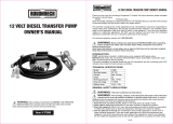
TOOLS & SUPPLIES NEEDED
Adj. Wrench
Wire Crimper/Stripper
Utility Knife
Pliers
Pipe Wrench
7/16 Wrench
Thread Tape
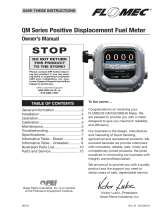
CONTENTS CHECKLIST
EZ-8 Model
with Easy Spin Collar
(Suction pipe not included)
25” - 40” Extension Pipe
15” - 25” Telescoping Suction Pipe
(D)
15” - 40” Telescoping Suction Pipe (2 pc)
(E)
90° Street Elbow
(F)
Manual
Nozzle
(A)
Pump Assembly
with Spin Collar
(A)
Pump Assembly
(C)
Spin Collar
Gasket
(B)
Tank Adapter
(H)
Wire Connector
(J)
Fuse
(G)
Discharge Hose
4
Before proceeding with installation determine if the pump will be temporarily or permanently wired to
your vehicle
.
Temporary Wiring
Permanent Wiring
Alligator Clamps Terminal Post Rings
(Not included) (Not included)

INSTALLATION
INSTALL PUMP ON TANK
Step 1
Wrap threads of EZ-8 inlet 3 or 4 times with thread
tape.
NOTE:
For EZ-8 with Spin Collar, wrap tank
adapter bung threads 3 or 4 times with
thread tape, and then tighten into tank
(Figure 1).
Step 4
Thread the suction pipe into the pump’s inlet fit-
ting and tighten until snug.
Step 5
Before installing the pump on the tank, clean the
tank interior of all dirt and foreign material
Step 6
Fully extend the telescoping portion of the suction
pipe. Carefully insert suction pipe into the tank
opening, position pump and tighten securely.
NOTE:
Be sure tank is properly vented
(Vent cap sold separately) (Figure 3).
NOTE:
For EZ-8 with Spin Collar, securely
tighten spin collar.
Vent Cap
(Sold Separately)
Figure 3
Figure 1
INSTALL ELBOW, HOSE & NOZZLE
Step 1
Seal the threaded ends of the 90° street elbow (E)
and both ends of the discharge hose (G) with 3 to
4 turns of thread tape.
Step 2
Using pliers, remove the plastic plug from outlet
port on top of pump. Thread the 90° street elbow
into outlet port and tighten securely.
Step 3
Thread one end of hose into the 90° street elbow
and tighten securely. Thread opposite end of hose
into nozzle (F) and tighten securely (Figure 4).
Step 2
Using pliers, remove the plastic plug from inlet
port on bottom of pump. Note: For EZ-8 models
with Spin Collar, place the spin collar gasket
(C) into the inlet fitting on bottom of pump
(see Figure 2).
Figure 2
Step 3
Wrap the threaded end of the telescoping suction
pipe (D) with 3 to 4 turns of thread tape.
Note: If your tank is 15” - 25” deep, do not use
the included suction pipe extension; if your
tank is 25” - 40” deep, attach the suction pipe
extension.
Figure 4
NOTE: Aluminum Tank Installation
-
To prevent thread galling of aluminum
fittings, always prepare the threads for
assembly using an anti-seize compound
such as Loctite® 567TM, Hernon® Drip-
stop® 940, or equivalent.
5

Step 4
Place the nozzle into the nozzle holder on the end
of the pump motor housing. Note that the nozzle
cannot be placed in the holder unless the pump
switch is OFF (Figure 5).
Step 5
If the power cord provided is too long, cut to de-
sired length. Using utility knife, carefully strip 3 to 4
inches (7.5 to 10 cm) of outer insulation from end
of power cord. DO NOT CUT INNER WIRES.
Next, strip ¼ inch (0.6 cm) of insu- lation from the
black and red power cord wires.
Step 6
For a negative ground system, first disconnect the
vehicle’s ground wire, and then wire as follows:
Insert one end of the fuse (J) into the wire con-
nector (H) and crimp. Insert the red power cord
wire into the other end of the wire connector and
crimp. Make sure the fuse is positioned outside
of hazardous areas and as close to the battery
as possible. Make a solid electrical connection to
the grounded side of the battery with the remain-
ing black wire. Connecting directly to the battery
terminal or the end of the battery cable is recom-
mended.
Step 7
For temporary wiring: Connect the red and black
power cords to alligator clamps (not included)
(Figure 6).
Figure 5
CONNECT TO A POWER SOURCE
Please consult the Owner’s Manual for your vehicle
before proceeding.
NOTE:
The pump is designed for use with a 12-
volt power source. Do not attempt installation
on a 24-volt or 115-volt system.
WARNING: Do not attempt to power the pump
from vehicle wiring smaller than 14 gauge,
such as the cigarette lighter wire, as these thin
wires could overheat and cause a fire.
NOTE:
This pump is pre-wired for installation in
CLASS I, DIVISION 2 locations such as portable
fuel tanks, trailers, etc. Connection to a battery
will depend upon the application.
Figure 6
Step 8
For permanent wiring:
Connect the red and black power cords to termi-
nal post rings (not included) (Figure 7).
WARNING: If pump is to be installed in
a CLASS I, DIVISION I location please
contact GPI for the appropriate product.
Figure 7
Verify switch is in OFF position, then route the
electrical wires to the source of the vehicle power
system. Be sure to support the wires as neces-
sary and protect them from sharp edges, heat or
anything that could damage the wires.
Step 9
Check all connections to make sure they are con-
nected per instructions and all electrical codes.
The installation is now complete.
6

OPERATION
Always follow safety precautions when oper-
ating this equipment. Review the Safety In-
structions. Before each use, repair leaks around
seals or connections. Make sure hoses are in good
condition and connections are tight. Make sure the
work area is dry. Make sure the pump is properly
grounded. Repair any corroded or damaged wiring
before use. Ensure the tank contains enough fuel.
Make sure the fuel is not contaminated with debris.
Tighten loose tank lids regularly.
TROUBLESHOOTING
Always disconnect power before repairing or ser-
vicing the pump. Never apply power to the sys-
tem when any coverplate is removed.
MOTOR DOES NOT RUN
•
Auxiliary temperature-limiting device tripped.
Turn pump switch off. Allow motor to cool.
Device resets automatically. Try again.
Fuse blown. Inspect fuse in fuse holder. If
blown, replace (See Figure 8).
•
To Dispense Fuel
Turn on the pump by removing the nozzle from the
holder and pushing up the switch lever. Insert the
nozzle into the receiving tank and squeeze the han-
dle to start fuel flow. When done, release the nozzle
handle, turn the pump off, and return the nozzle to
its holder.
This pump is designed to be self-priming. If fuel
is not delivered within 15 to 20 seconds, turn the
pump off and refer to priming information in the
Troubleshooting Section.
An automatic bypass valve prevents pressure
build up when the pump is on with the nozzle
closed. To avoid pump damage, do not run the
pump more than 5 minutes with the nozzle closed.
After running the pump for a maximum of 15 min-
utes, allow it to cool for 30 minutes.
Figure 8
•
Switch defective. Remove electrical cover-
plate and inspect switch (Figure 9). Replace if
necessary.
Auxiliary Temperature-Limiting Device
The motor is provided with an internal auxiliary
temperature-limiting device. Excessive motor heat
can trip the device. It resets automatically after
the motor has cooled. Pump will restart automati-
cally when cooled if switch is in the “ON” position.
MAINTENANCE
This pump is designed for minimum maintenance.
Motor bearings are sealed and require no lubrica-
tion. Inspect the pump and components regularly
for fuel leaks and make sure the hose and power
cord are in good condition. Keep the pump exteri-
or clean to help identify leaks.
Do not use this pump for water, chemicals or
herbicides. Dispensing any fluid other than that
listed in this manual will damage the pump. Use
of the pump with unauthorized fluids will void the
warranty.
Figure 9
•
Switch or electrical connection faulty. Inspect
for defective wiring or switch, or improper
electrical connections. Replace as necessary.
Motor burned out. Inspect and replace as
necessary.
•
MOTOR RUNS BUT DOES NOT
PUMP FLUID
•
•
Fuel level low. Fill tank.
Strainer clogged or defective. Inspect and
clean as required (See Figure 10).
7

Strainer
Figure 12
•
Bypass poppet binding or damaged. Re-
move the bypass poppet, spring, and O-ring
(Figure 13). Clean cavity. Inspect and replace
as necessary.
Figure 10
•
Suction pipe clogged, damaged, or missing.
Remove pump from tank. Inspect suction
pipe. Clean or replace, as necessary.
Gear coverplate or O-ring damaged. Remove
and inspect the coverplate and O-ring (See
Figure 11). Replace as necessary.
•
Figure 13
•
System air leak. Tighten all pump fittings and
connections. Inspect suction pipe for leaks or
damage.
Poor connections or low voltage. Make sure
electrical connections are secure. Also check
battery voltage.
Motor running backwards due to incorrect po-
larity (See Figure 14). Connect red wire to
positive (+) ungrounded side of battery.
•
Figure 11
Bypass poppet O-ring worn, missing or dirty. In-
spect the O-ring. Replace as necessary. To re-
move the o-ring, first remove the gear coverplate
and drive gears. Using an index finger, push the
poppet assembly downward through the outlet
port, and then remove the o-ring using an o-ring
puller (See Figure 12).
•
c
Figure 14
8

LOW FLOWRATE
•
Running too long in bypass mode. Limit by-
pass operation to 5 minutes.
Strainer clogged. Inspect and clean as re-
quired.
Suction pipe clogged or damaged. Remove
pump from tank. Inspect suction pipe. Clean
or replace as necessary.
•
•
Fuel tank empty. Fill tank.
Strainer partially clogged. Inspect and clean
as required.
Suction pipe clogged or damaged. Remove
pump from tank. Inspect suction pipe. Clean
or replace.
Suction pipe too close to tank bottom. Suction
pipe must have at least 1/2 in. (1.2 cm) clear-
ance from bottom of tank.
System air leak. Tighten all pump fittings and
connections. Inspect suction pipe for leaks or
damage. Replace as necessary.
Poor connections or low voltage. Make sure
electrical connections are secure. Also check
battery voltage.
•
•
•
SPECIFICATIONS
•
•
•
MOTOR STALLS WHEN OPERATING IN
BYPASS MODE
•
Bypass poppet binding or damaged. Remove
the bypass poppet, spring, and O-ring. Clean
cavity. Inspect components and replace as
necessary.
Wiring defective. Use instructions in the In-
stallation Section to ensure proper electrical
connections.
Gears locked. Remove gear coverplate and
inspect gears and drive key. Replace, if worn.
Motor defective. Inspect and replace as nec-
essary.
•
•
•
SWITCH FAILS TO OPERATE MOTOR
•
Switch or electrical connections faulty. Inspect
for blown fuse, defective wiring/switch, or im-
proper electrical connections. Replace as nec-
essary.
Motor burned out. Inspect and replace as nec-
essary.
•
RAPID OVERHEATING OF MOTOR
•
•
Fuel level low. Fill tank.
Duty cycle too long. Pump operation should
not exceed the standard duty cycle of 15 min-
utes on and 30 minutes off. Allow the pump to
cool for 30 minutes.
9
Applications for
EZ-8
Low viscosity petroleum fuels:
Gasoline (up to 15% alcohol blends
such as E15
Diesel fuel (up to 20% biodiesel
blends such as B20)
Kerosene
Designed for permanent mounting
on vented storage tanks
Applications for
EZ-8 Methanol
Methanol and Ethanol
Gasoline
Diesel fuel (up to 20% biodiesel
blends such as B20)
Kerosene
Pump housing
Lightweight, corrosion-resistant,
cast
aluminum
body
Performance:
Pump rate
Up to 8 GPM (30 LPM)
Duty cycle
15 minutes ON, 30 minutes OFF
Suction lift
Manual
nozzle:
Up
to
5
.
5
ft
(1
.
7m)
Operating tem-
perature
-20oF to +125oF (-29oC to +52oC)
Operating
pres-
sure
15 PSI
Electrical
specifications
Input: 12-volt DC
Current draw: 11 amp
Motor: 2100 RPM, UL Listed to UL
Canadian Standards, 1/10 HP (75
watts)
Mechanical
connections
Bung:
2
in
.
NP
T
,
Inlet:
3/4
in
.
NP
T
,
Outlet:
3/4
in
.
NPT
Accessories
5/8
in
.
x
10
ft
.
(3.
0m)
Buna-N
elec
-
trically conductive discharge hose
Standar
d
3/4
in.
manual
unleaded
nozzle
Cor
d:
15
ft
.
(4.
6m),
14/2
gauge
Fuse: 20 amp
Strain relief grip
Shipping weight
16
.
0
lbs
(7.
5
kg)
with
manual
nozzle

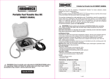
ILLUSTRATED PARTS LIST - EZ-8 & EZ-8 METHANOL
1
4
5
17
9
8
A
12
3
11
7
19
16
6
13
14
18
10
21
15
For Spin collar models
20
22
23
Individual Parts
Kits and Accessories
10
Item
No. Part No. Description
110909-1
Kit, Bung Adapter (Spin Collar model)
13750006
Drive Key Kit (includes Drive Key)
13750001
Fuse Holder Kit (includes Fuse Holder, Fuse, Wire)
110032-501
Kit, Gasket, Union Ring (Spin Collar Model)
13750004
Gear Coverplate Kit (includes Gear Coverplate,
O-Ring #6)
13750003
Gear Kit (includes 2 Gears & Drive Key)
or (Kit )
For pumps mfg. on or before Jan. 8, 2016
137500-13
Gear Kit (includes 2 Gears, coverplate, #6 o-ring)
or (Kit ) For pumps mfg. Jan. 15, 2016 or later
136157-01
Hose, (3/4-inch NPT x 5/8 x 10 ft.)
110155-1
Nozzle, Manual 3/4 in., Unleaded
13750005
Overhaul Kit (includes Drive Key, Motor Shaft
Seal, 2 Gears, O-Ring #8, O-Ring #6, O-Ring #18)
For pumps mfg. on or before Jan. 8, 2016
137500-14
Overhaul Kit (includes Motor Shaft Seal #3,
2 Gears, O-Ring #8, O-Ring #6, O-Ring #17, switch
lever, shaft seal)
For pumps mfg. Jan. 15, 2016 or later
110412-15
Power Cord, 14 ga. x 15 ft. (4.6 m)
904002-17
Strain Relief Sealing Grip
13750002
Wet Seal Kit (includes Motor Shaft Seal, O-Ring
#6, O-Ring #18
Item
No. Part No. Description Req’d.
1
137078-501
Motor, 12-Volt ..................................................1
2
904004-2
Screw, Hex Head Cap ..................................... 4 ea.
3
11002502
Motor Shaft Seal ........................................... 1
4
137031-01
Bypass Poppet .............................................. 1
5
137039-06
Spring, Bypass Poppet .................................. 1
6
901003-76
O-Ring ........................................................... 1
7
123038-1
Inlet Strainer ................................................. 1
8
901003-70
O-Ring ........................................................... 1
9
137014-01
Switch Coverplate ......................................... 1
10
110032-1
Gasket, Union Ring ............................................1
11
902007-530
Switch ........................................................... 1
12
110360-02
Nozzle Cover ................................................. 1
13
904006-86
Tapping Screw ...................................................
2 ea.
14
904002-23
SEMS Screw .................................................. 6 ea.
15
904007-65
Washer, Flat .................................................. 4 ea.
16
137007-01
Switch Lever Assy ......................................... 1
17
901003-77
O-Ring ........................................................... 1
18
137012-01
Gear Coverplate ........................................... 1
137012-02
Gear Coverplate, ENP (For Methanol models) ...1
19
904003-84
Screw, Switch Bracket................................... 1
20
110241-01
Telescoping Suction Pipe .............................. 1
NOTE: Does not fit Spin Collar model
21
110037-1
Tank Bung Adapter (Spin Collar model) ........ 1

11
Notes:

WARRANTY
© 2020 Great Plains Industries, Inc. All Rights Reserved.
921803-01 Rev G
10/20
Great Plains Industries, Inc. 5252 E. 36th Street North, Wichita, KS USA
To make a claim against this warranty, contact the GPI Customer Service
67220-3205, hereby provides a limited warranty against defects in material
Department at
and workmanship on all products manufactured by Great Plains Industries,
316-686-7361 or 800-835-0113. Or by mail at:
Inc. This product includes a 2 year warranty from date of purchase as
evidenced by the original sales receipt. A 30 month warranty from product
Great Plains Industries, Inc.
date of manufacture will apply in cases where the original sales receipt is not 5252 E. 36
th
St. North, Wichita, KS, USA 67220-3205
available. Reference product labeling for the warranty expiration date based
on 30 months from date of manufacture. Manufacturer’s sole obligation under GPI will step you through a product troubleshooting process to determine
the foregoing warranties will be limited to either, at Manufacturer’s option,
appropriate corrective actions.
replacing or repairing defective Goods (subject to limitations hereinafter GREAT PLAINS INDUSTRIES, INC., EXCLUDES LIABILITY UNDER THIS
provided) or refunding the purchase price for such Goods theretofore paid by WARRANTY FOR DIRECT, INDIRECT, INCIDENTAL AND CONSEQUENTIAL
the Buyer, and Buyer’s exclusive remedy for breach of any such warranties
will be enforcement of such obligations of Manufacturer. The warranty shall DAMAGES INCURRED IN THE USE OR LOSS OF USE OF THE PRODUCT
extend to the purchaser of this product and to any person to whom such WARRANTED HEREUNDER.
product is transferred during the warranty period.
The company herewith expressly disclaims any warranty of merchantability
This warranty shall not apply if:
or fitness for any particular purpose other than for which it was designed.
A.
the product has been altered or modified outside the warrantor’s duly This warranty gives you specific rights and you may also have other rights
appointed representative;
which vary from U.S. state to U.S. state.
B.
the product has been subjected to neglect, misuse, abuse or damage
or has been installed or operated other than in accordance with the
Note: In compliance with MAGNUSON MOSS CONSUMER WARRANTY ACT
manufacturer’s operating instructions.
– Part 702 (governs the resale availability of the warranty terms).
/