
user's manual
nxl frequency converters
alcnf127
lift door application
application manual

1
2 • vacon Introduction
Telephone: +358-201-2121 • Fax: +358-201-212 205
Vacon Lift Door Application
(Software alcnf127) Ver. 1.03
INDEX
1. INTRODUCTION.................................................................................................................. 3
2. CONTROL I/O...................................................................................................................... 4
3. PARAMETER LISTS ............................................................................................................ 5
3.1 MONITORING VALUES (CONTROL KEYPAD: MENU M1) ........................................................... 5
3.2 BASIC PARAMETERS (CONTROL KEYPAD: MENU P2 Æ P2.1)................................................. 6
3.3 INPUT SIGNALS (CONTROL KEYPAD: MENU P2 Æ P2.2) ......................................................... 8
3.4 OUTPUT SIGNALS (CONTROL KEYPAD: MENU P2 Æ P2.3).................................................... 10
3.5 DRIVE CONTROL PARAMETERS (CONTROL KEYPAD: MENU P2 Æ P2.4) ............................. 11
3.6 MOTOR CONTROL PARAMETERS (CONTROL KEYPAD: MENU P2 Æ P2.5) ........................... 12
3.7 PROTECTIONS (CONTROL KEYPAD: MENU P2 Æ P2.6) ......................................................... 13
3.8 AUTORESTART PARAMETERS (CONTROL KEYPAD: MENU P2 Æ P2.7) ................................ 14
3.9 LIFT DOOR PARAMETERS (CONTROL KEYPAD: MENU P2 Æ P2.8) ....................................... 15
3.10 KEYPAD CONTROL (CONTROL KEYPAD: MENU K3) ............................................................... 16
3.11 SYSTEM MENU (CONTROL KEYPAD: MENU S6) ..................................................................... 16
3.12 EXPANDER BOARDS (CONTROL KEYPAD: MENU E7) ............................................................ 16
4. DESCRIPTION OF PARAMETERS ...................................................................................... 17
4.1 BASIC PARAMETERS................................................................................................................ 17
4.2 INPUT SIGNALS ........................................................................................................................ 22
4.3 OUTPUT SIGNALS..................................................................................................................... 26
4.4 DRIVE CONTROL ....................................................................................................................... 30
4.5 MOTOR CONTROL..................................................................................................................... 34
4.6 PROTECTIONS........................................................................................................................... 37
4.7 AUTO RESTART PARAMETERS ................................................................................................ 44
4.8 LIFT DOOR PARAMETERS ........................................................................................................ 45
4.9 KEYPAD CONTROL PARAMETERS ........................................................................................... 46
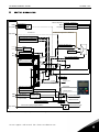
5. CONTROL SIGNAL LOGIC ................................................................................................. 47
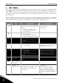
6. FAULT TRACING............................................................................................................... 48

1
Introduction vacon • 3
24-hour support: +358-40-8371 150 • Email: [email protected]
Lift Door Application
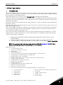
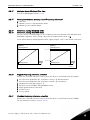
1. INTRODUCTION
The Lift Door Application for Vacon NXL uses direct frequency reference from the preset speed as a
default. The direct frequency reference can be selected from the analogue inputs, fieldbus, keypad,
preset speeds or motor potentiometer.
Special parameters for Lift Door Control (Group P2.8) can be browsed and edited.
The preset speed can be defined by door position switch, including door open low speed, door open
hold, door close low speed and door close hold switches. Please find more parameter about preset
speed setting in M2.8.
Also more accelerate time and decelerate time parameters can be set at different position defined
by position switch.
The input type can be select by parameter from P2.2.22 to P2.2.28, which has normal, inversion, rise
edge and fall edge choices.
The Lift Door Application defines forward to close the door and reverse to open the door as default.
Four warning and fault codes have been added to supervise position switch. The motor will run at
safe speed once happens warning or fault.
There’re three drive run mode, demo, central system and tuning can be selected by P2.8.1. Demo
mode usually is used as demonstrate, central system mode is a standard run mode, and tuning is
used to install and test as purpose.
• Digital inputs DIN2, DIN3, (DIN4) and optional dig. Inputs DIE1, DIE2, DIE3 are freely
programmable.
• Internal and optional digital/relay and analogue outputs are freely programmable.
• Analogue input 1 can be programmed as current input, voltage input or digital input DIN4.
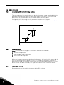
NOTE! If the analogue input 1 has been programmed as DIN4 with parameter 2.2.6 (AI1 Signal
Range), check that the jumper selections (
Figure 1- 1) are correct.
Additional functions:
• Fire mode and safe input
• Switch status and door cycle times
• Identification
• Programming wizard
• Actual value supervision function: fully programmable; off, warning, fault
• Programmable Start/Stop and Reverse signal logic
• RS485 communication as standard
• Analogue input range selection, signal scaling, inversion and filtering
• Frequency limit supervision
• Programmable start and stop functions
• DC-brake at start and stop
• Prohibit frequency area
• Programmable U/f curve and U/f optimisation
• Adjustable switching frequency
• Autorestart function after fault
• Protections and supervisions (all fully programmable; off, warning, fault):
• Current input fault
• External fault
• Output phase
• Under voltage
• Earth fault
• Motor thermal, stall and underload protection
• Thermistor
• Fieldbus communication
• Option board
•
Position switch

1
4 • vacon Control I/O
Telephone: +358-201-2121 • Fax: +358-201-212 205
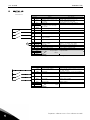
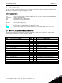
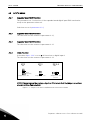
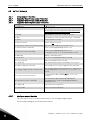
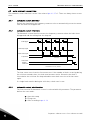
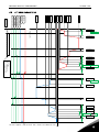
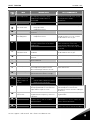
2. CONTROL I/O
Terminal Signal Description
1
+10V
ref
Reference output Voltage for potentiometer, etc.
2
AI1+
Analogue input, voltage range
0—10V DC.
Voltage input frequency reference
Can be programmed as DIN4
3
AI1- I/O Ground Ground for reference and controls
4
AI2+
5
AI2-
/GND
Analogue input, voltage range
0—10V DC, or current range
0/4—20mA
Current input frequency reference
6
+24V Control voltage output Voltage for switches, etc. max 0.1 A
7
GND I/O ground Ground for reference and controls
8
DIN1 Start forward Contact closed = start forward
9
DIN2 Start reverse (programmable) Contact closed = start reverse
10
DIN3 Open low speed
(programmable)
Contact closed = open low speed
11
GND
I/O ground Ground for reference and controls
18
AO1+
19
AO1-
Output frequency
Analogue output
Programmable
Range 0—20 mA/R
L
, max. 500Ω
A
RS 485 Serial bus Differential receiver/transmitter
B
RS 485 Serial bus Differential receiver/transmitter
30
+24V 24V aux. input voltage Control power supply backup
21
RO1
22
RO1
23
RO1
Relay output 1
FAULT
Programmable
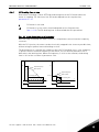
Table 1- 1. Lift Door application default I/O configuration.
Terminal Signal Description
1
+24V
Control voltage output Control voltage output; voltage for witches
etc, max. 150 mA
2
GND I/O ground Ground for controls, e.g. for +24 V and DO
3
DIN1 Open hold
Digital input 1 (DIN4)
4
DIN2 Close low speed
Digital input 2 (DIN5)
5
DIN3 Close hold
Digital input 3 (DIN6)
6
DO1 Digital output Digital output 1
24
RO2
25
RO2
26
RO2
Relay output 2
RUN
Programmable
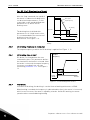
Table 1- 2. OPTAA configuration.
Reference
Potentiometer
mA

1
Parameter lists vacon • 5
24-hour support: +358-40-8371 150 • Email: [email protected]
3. PARAMETER LISTS
On the next pages you will find the lists of parameters within the respective parameter groups. The
parameter descriptions are given on pages
17 to 44.
Column explanations:
Code = Location indication on the keypad; Shows the operator the present param. Number
Parameter = Name of parameter
Min = Minimum value of parameter
Max = Maximum value of parameter
Unit = Unit of parameter value; given if available
Default = Value preset by factory
Cust = Customer’s own setting
ID = ID number of the parameter (used with PC tools)
= On the parameter code: parameter value can only be changed after the FC has
been stopped.
3.1 Monitoring values (Control keypad: menu M1)
The monitoring values are the actual values of parameters and signals as well as statuses and
measurements. Monitoring values cannot be edited.
See Vacon NXL User’s Manual, Chapter 7.4.1 for more information.
Code Parameter Unit ID Description
V1.1 Output frequency Hz 1 Frequency to the motor
V1.2 Frequency reference Hz 25
V1.3 Motor speed rpm 2 Calculated motor speed
V1.4 Motor current A 3 Measured motor current
V1.5 Motor torque % 4
Calculated actual torque/nom. torque of the
motor
V1.6 Motor power % 5 Calculated actual power/nom. power of the motor
V1.7 Motor voltage V 6 Calculated motor voltage
V1.8 DC-link voltage V 7 Measured DC-link voltage
V1.9 Unit temperature ºC 8 Heat sink temperature
V1.10 Analogue input 1 13 AI1
V1.11 Analogue input 2 14 AI2
V1.12 Analogue output current mA 26 AO1
V1.13 Analogue output current 1, expander board mA 31
V1.14 Analogue output current 2, expander board mA 32
V1.15 DIN1, DIN2, DIN3 15 Digital input statuses
V1.16 DIE1, DIE2, DIE3 33 I/O expander board: Digital input statuses
V1.17 RO1 34 Relay output 1 status
V1.18 ROE1, ROE2, ROE3 35 I/O exp. board: Relay output statuses
V1.19 DOE 1 36 I/O exp. board: Digital output 1 status
V1.20 Operate counter % 67 Door operate time, 0-65535
V1.21 Door DIN status % 68 The status of position switch (DIN)
Table 1- 3. Monitoring values

1
6 • vacon Parameter lists
Telephone: +358-201-2121 • Fax: +358-201-212 205
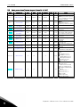
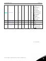
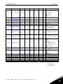
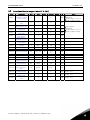
3.2 Basic parameters (Control keypad: Menu P2 Æ P2.1)
Code Parameter Min Max Unit Default Cust ID Note
P2.1.1 Min frequency 0,00 Par. 2.1.2 Hz 0,00 101
P2.1.2 Max frequency Par. 2.1.1 320,00 Hz 50,00
102
NOTE: If f
max
> than the
motor synchronous speed,
check suitability for motor
and drive system
P2.1.3 Current limit 0,1 x I
L
1,5 x I
L
A I
L
107
NOTE: Formulas apply
approximately for
frequency converters up to
P2.1.4
Nominal voltage of
the motor
180 690 V 2:230v
110
P2.1.5
Nominal frequency
of the motor
30,00 320,00 Hz 50,00
111
Check the rating plate of
the motor
P2.1.6
Nominal speed of
the motor
300 20 000 rpm 1440
112
The default applies for a 4-
pole motor and a nominal
size frequency converter.
P2.1.7
Nominal current of
the motor
0,3 x I
L
1,5 x I
L
A I
H
113
Check the rating plate of
the motor
P2.1.8
Motor cosϕ
0,30 1,00 0,85
120
Check the rating plate of
the motor
P2.1.9 Start function 0 2 0
505
0=Ramp
1=Flying start
2=Conditional flying start
P2.1.10 Stop function 0 1 0
506
0=Coasting
1=Ramp
P2.1.11 U/f optimisation 0 1 1
109
0=Not used
1=Automatic torque boost
P2.1.12 I/O reference 0 5 6
117
0=AI1
1=AI2
2=Keypad reference
3=Fieldbus reference
(FBSpeedReference)
4=Motor potentiometer
5=AI1/AI2 selection
6=Preset speed
P2.1.13 DIN2 function 0 8 1
319
0=Not used
1=Start Reverse
(DIN1=Start forward)
2=Reverse (DIN1=Start)
3=Stop pulse (DIN1=Start
pulse)
4=External fault, cc
5=External fault, oc
6=Run enable
7=Door open low
8= Door open hold

1
Parameter lists vacon • 7
24-hour support: +358-40-8371 150 • Email: [email protected]
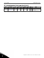
P2.1.14 DIN3 function 0 18 6
301
0=Not used
1=Reverse
2=External fault, cc
3=External fault, oc
4=Fault reset
5=Run enable
6=Door open low
7=Door open hold
8=DC-braking command
9=Motor pot. UP (cc)
10=Motor pot. DOWN (cc)
11=ThermFlt/Wrn
12=I/O Terminal
13=Fieldbus
14=AI1/AI2 Sel
15= Door close low
16= Door close hold
17=Fire mode
18=Safe enable
P2.1.15 Automatic restart 0 1 0
731
0=Not used
1=Used
P2.1.16 Parameter conceal 0 1 0
854
0=All visual
1=Basic
P2.1.17 Password 0 65535 0
852
0-65535
0-1=disable password
when access; and
password status, 0 is
disable, 1 is active
2-65535= password data
Table 1- 4. Basic parameters P2.1
CP= control place

1
8 • vacon Parameter lists
Telephone: +358-201-2121 • Fax: +358-201-212 205
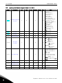
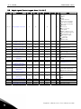
3.3 Input signals (Control keypad: Menu P2 Æ P2.2)
Code Parameter Min Max Unit Default Cust ID Note
P2.2.1
Expander board DIE1
function
0 18 7
368
0=Not used
1=Reverse
2=External fault, cc
3=External fault, oc
4=Fault reset
5=Run enable
6=Door open low
7=Door open hold
8=DC-braking command
9=Motor pot. UP (cc)
10=Motor pot. DOWN (cc)
11=ThermFlt/Wrn
12=I/O Terminal
13=Fieldbus
14=AI1/AI2 Select
15= Door close low
16= Door close hold
17=Fire mode
18=Safe enable
P2.2.2
Expander board DIE2
function
0 18 15
330
As par. 2.2.1, except:
13=Interlock 2
P2.2.3
Expander board DIE3
function
0 18 16
369
As par. 2.2.1, except:
13=Interlock 3
P2.2.4 DIN4 function (AI1)
0
18 18
499
Used if P2.2.6 = 0
Selections as in par.2.2.3
P2.2.5
AI1 signal
selection
0
10
377
10=AI1 (1=Local,
0=input 1)
11=AI2 (1=Local,
1= input 2)
20=Exp. AI1
(2=exp.board
0=input 1)
21=Exp AI2
(2=exp.board
1=input 2)
P2.2.6 AI1 signal range
1
4 3
379
0=Digital input 4
1=0mA – 20mA (MF4-->)
2=4mA – 20mA (MF4-->)
3=0V – 10V
4=2V – 10V
Not used if AI1 Custom
min > 0% or AI1 custom
max. < 100%
Note! See NXL User’s
manual, chapter 7.4.6: AI1
mode
P2.2.7
AI1 custom
minimum setting
0,00
100,00 % 0,00
380
P2.2.8
AI1 custom
maximum setting
0,00
100,00 % 100,00
381
P2.2.9 AI1 inversion
0
1 0
387
0=Not inverted
1=Inverted
P2.2.10 AI1 filter time
0,00
10,00 s 0,10 378 0=No filtering

1
Parameter lists vacon • 9
24-hour support: +358-40-8371 150 • Email: [email protected]
P2.2.11 AI2 signal selection
0
11 388 As par. 2.2.5
P2.2.12 AI2 signal range
1
4 2
390
Not used if AI2 Custom
min <> 0% or AI2 custom
max. <> 100%
1=0—20 mA
2=4—20 mA
3=0V – 10V
4=2V – 10V
P2.2.13
AI2 custom
minimum setting
0,00
100,00 % 0,00
391
P2.2.14
AI2 custom
maximum setting
0,00
100,00 % 100,00
392
P2.2.15 AI2 inversion
0
1 0
398
0=Not inverted
1=Inverted
P2.2.16 AI2 filter time
0,00
10,00 s 0,10 389 0=No filtering
P2.2.17
Motor potentiometer
frequency reference
memory reset
0
2 1
367
0=No reset
1=Reset if stopped or
powered down
2=Reset if powered down
P2.2.18
Reference scaling
minimum value
0,00
P2.2.19 0,00
344
Does not affect the
fieldbus reference (Scaled
between par. 2.1.1 and
par. 2.1.2)
P2.2.19
Reference scaling
maximum value
P2.2.18
320,00 0,00
345
Does not affect the
fieldbus reference (Scaled
between par. 2.1.1 and
par. 2.1.2)
P2.2.20
Keypad control
reference selection
0 5 2
121
0=AI1
1=AI2
2=Keypad reference
3=Fieldbus reference
(FBSpeedreference)
4=Motor potentiometer
5=AI1/AI2 Select
6=Preset speed
P2.2.21
Fieldbus control
reference selection
0 5 3
122 See above
P2.2.22
DIN 1 Type 0 3 0
740
0=Normal
1=Inversion
2=Rise edge
3=Fall edge
P2.2.23 DIN 2 Type 0 3 0 741 See P2.2.22
P2.2.24 DIN 3 Type 0 3 0 742 See P2.2.22
P2.2.25 Exp DIN 1 Type 0 3 0 743 See P2.2.22
P2.2.26 Exp DIN 2 Type 0 3 0 744 See P2.2.22
P2.2.27 Exp DIN 3 Type 0 3 0 745 See P2.2.22
P2.2.28 DIN4(AI1) Type 0 3 0 746 See P2.2.22
Table 1- 5. Input signals, P2.2
CP=control place
cc=closing contact
oc=opening contact

1
10 • vacon Parameter lists
Telephone: +358-201-2121 • Fax: +358-201-212 205
3.4 Output signals (Control keypad: Menu P2 Æ P2.3)
Code Parameter Min Max Unit Default Cust ID Note
P2.3.1 Relay output 1 function 0 17 16
313
0=Not used
1=Ready
2=Run
3=Fault
4=Fault inverted
5=FC overheat warning
6=Ext. fault or warning
7=Ref. fault or warning
8=Warning
9=Reversed
10=Preset speed
11=At speed
12=Mot. regulator active
13=OP freq. limit superv.1
14=Control place: IO
15=Thermistor fault/
warning
16=Open end
17=Close end
P2.3.2
Expander board relay
output 1 function
0 17 17
314 As parameter 2.3.1
P2.3.3
Expander board relay
output 2 function
0 17 3
317 As parameter 2.3.1
P2.3.4
Expander board digital
output 1 function
0 17 1
312 As parameter 2.3.1
P2.3.5 Analogue output function 0 12 1
307
See par. 2.1.14
P2.3.6
Analogue output filter
time
0,00 10,00 s 1,00
308 0=No filtering
P2.3.7
Analogue output
inversion
0 1 0
309
0=Not inverted
1=Inverted
P2.3.8
Analogue output
minimum
0 1 0
310
0=0 mA
1=4 mA
P2.3.9 Analogue output scale 10 1000 % 100 311
P2.3.10
Expander board analogue
output 1 function
0 12 0 472 As parameter 2.1.14
P2.3.11
Expander board analogue
output 2 function
0 12 0
479 As parameter 2.1.14
P2.3.12
Output frequency limit 1
supervision
0 2 0
315
0=No limit
1=Low limit supervision
2=High limit supervision
P2.3.13
Output frequency limit 1;
Supervised value
0,00 Par. 2.1.2 Hz 0,00
316
P2.3.14
Analogue input
supervision
0 2 0
356
0=Not used
1=AI1
2=AI2
P2.3.15 AI supervision OFF limit 0,00 100,00 % 10,00 357
P2.3.16 AI supervision ON limit 0,00 100,00 % 90,00 358
P2.3.17 Relay output 1 ON delay 0,00 320,00 s 0,00 487 ON delay for RO1
P2.3.18 Relay output 1 OFF delay 0,00 320,00 s 0,00 488 OFF delay for RO1
Table 1- 6. Output signals, G2.3

1
Parameter lists vacon • 11
24-hour support: +358-40-8371 150 • Email: [email protected]
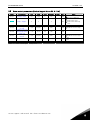
3.5 Drive control parameters (Control keypad: Menu P2 Æ P2.4)
Code Parameter Min Max Unit Default Cust ID Note
P2.4.1 Ramp 1 shape 0,0 10,0 s 0,0
500
0=Linear
>0=S-curve ramp time
P2.4.2 Brake chopper 0 3 0
504
0=Disabled
1=Used in Run state
3=Used in Run and Stop
state
P2.4.3 DC braking current 0,15 x I
n
1,5 x I
n
A Varies 507
P2.4.4
DC braking time
at stop
0,00 600,00 s 0,00
508 0=DC brake is off at stop
P2.4.5
Frequency to start
DC braking during
ramp stop
0,10 10,00 Hz 1,50
515
P2.4.6
DC braking time
at start
0,00 600,00 s 0,00
516 0=DC brake is off at start
P2.4.7 Flux brake 0 1 0
520
0=Off
1=On
P2.4.8 Flux braking current 0,0 Varies A 0,0 519
Table 1- 7. Drive control parameters, P2.4

1
12 • vacon Parameter lists
Telephone: +358-201-2121 • Fax: +358-201-212 205
3.6 Motor control parameters (Control keypad: Menu P2 Æ P2.5)
Code Parameter Min Max Unit Default Cust ID Note
P2.5.1 Motor control mode 0 1 0
600
0=Frequency control
1=Speed control
P2.5.2 U/f ratio selection 0 3 0
108
0=Linear
1=Squared
2=Programmable
3=Linear with flux optim.
P2.5.3
Field weakening
point
30,00 320,00 Hz 50,00
602
P2.5.4
Voltage at field
weakening point
10,00
200,00 % 100,00
603 n% x U
nmot
P2.5.5
U/f curve midpoint
frequency
0,00
par.
P2.5.3
Hz 50,00
604
P2.5.6
U/f curve midpoint
voltage
0,00 100,00 % 100,00
605
n% x U
nmot
Parameter max. value =
par. 2.5.4
P2.5.7
Output voltage at
zero frequency
0,00 40,00 % 0,00
606 n% x U
nmot
P2.5.8 Switching frequency 1,0 16,0 kHz 6,0 601 Depends on kW
P2.5.9
Overvoltage
controller
0 1 1
607
0=Not used
1=Used
P2.5.10
Undervoltage
controller
0 1 1
608
0=Not used
1=Used
P2.5.11 Identification 0 1 0
631
0=No action
1=ID no run
P2.5.12 MeasRsVoltDrop 0 2000 % 0
866
Measured Voltage drop at
stator resistance between
two phases with nom
current of motor. Unit:
256=10%
Table 1- 8. Motor control parameters, P2.6

1
Parameter lists vacon • 13
24-hour support: +358-40-8371 150 • Email: [email protected]
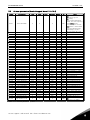
3.7 Protections (Control keypad: Menu P2 Æ P2.6)
Code Parameter Min Max Unit Default Cust ID Note
P2.6.1
Response to 4mA
reference fault
0 3 0
700
0=No response
1=Warning
2=Fault,stop acc. to 2.1.10
3=Fault,stop by coasting
P2.6.2
Response to external
fault
0 3 2
701
P2.6.3
Response to
undervoltage fault
1 3 2
727
P2.6.4
Output phase
supervision
0 3 2
702
P2.6.5
Earth fault
protection
0 3 2
703
P2.6.6
Thermal protection
of the motor
0 3 0
704
0=No response
1=Warning
2=Fault,stop acc. to 2.1.10
3=Fault,stop by coasting
P2.6.7
Motor ambient
temperature factor
–100,0 100,0 % 0,0
705
P2.6.8
Motor cooling factor
at zero speed
0,0 150,0 % 40,0
706
P2.6.9
Motor thermal time
constant
1 200 min 45
707
P2.6.10 Motor duty cycle 0 100 % 100 708
P2.6.11 Stall protection 0 3 1 709 As par. 2.6.1
P2.6.12 Stall current limit 0,1 I
nmotor
x 2 A
I
nmotor
x1.3
710
P2.6.13 Stall time limit 1,00 120,00 s 15,00 711
P2.6.14 Stall frequency limit 1,0 P 2.1.2 Hz 25,0 712
P2.6.15 Underload protection 0 3 0 713 As par. 2.6.1
P2.6.16
Underload curve at
nominal frequency
10,0 150,0 % 50,0
714
P2.6.17
Underload curve at
zero frequency
5,0 150,0 % 10,0
715
P2.6.18
Underload
protection time
limit
2,00 600,00 s 20,00
716
P2.6.19
Response to
thermistor fault
0 3 2
732 As par. 2.6.1
P2.6.20
Response to
fieldbus fault
0 3 2
733 As par. 2.6.1
P2.6.21
Response to slot
fault
0 3 2
734 As par. 2.6.1
Table 1- 9. Protections, P2.6

1
14 • vacon Parameter lists
Telephone: +358-201-2121 • Fax: +358-201-212 205
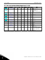
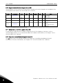
3.8 Autorestart parameters (Control keypad: Menu P2 Æ P2.7)
Code Parameter Min Max Unit Default Cust ID Note
P2.7.1 Wait time 0,10 10,00 s 0,50 717
P2.7.2 Trial time 0,00 60,00 s 30,00 718
P2.7.3 Start function 0 2 0
719
0=Ramp
1=Flying start
2=According to par. 2.1.9
Table 1- 10. Autorestart parameters, P2.7

1
Parameter lists vacon • 15
24-hour support: +358-40-8371 150 • Email: [email protected]
3.9 Lift door parameters (Control keypad: Menu P2 Æ P2.8)
Code Parameter Min Max Unit Default Cust ID Note
P2.8.1 Door Run Mode 0 2 2
851
0=Demo mode
1=Central system
2=Tuning
Note, demo and tuning
mode, the start request is
from start button,
reverse request is from
left button。Demo mode
is used to demonstrate,
and tuning is used to
identify motor direction
P2.8.2 Open Start Acc.T 0.1 10.0 s 2.0 747 Open start acc. time
P2.8.3 Open Start Time 0.01 10.00 s 1.00 748 Open start time
P2.8.4 Open Start Speed 0.00 P2.1.2 Hz 5.00 749 Open start speed
P2.8.5 Open Norm Acc.T 0.1 10.0 s 2.0 750 Open normal acc. time
P2.8.6 Open Norm Speed 0.00 P2.1.2 Hz 20.00 751 Open normal speed
P2.8.7 Open Low Dec.T 0.1 10.0 s 2.0 752 Open low dec. time
P2.8.8 Open Low Speed 0.00 P2.1.2 Hz 8.00 753 Open low speed
P2.8.9 Open Hold Dec.T 0.1 10.0 s 2.0 754 Open hold dec. time
P2.8.10 Open Hold Time 0.01 10.00 s 2.00 755 Open hold time
P2.8.11 Open Hold Low 0.00 P2.1.2 Hz 3.00 756 Open hold low speed
P2.8.12 Open Hold Time1 0.01 10.00 s 0.20 757 Open hold time 1
P2.8.13 Open Hold Acc.T 0.1 10.0 s 2.0 758 Open hold acc. time
P2.8.14 Open Hold High 0.00 P2.1.2 Hz 8.00 759 Open hold high speed
P2.8.15 Open Hold Time2 0.01 10.00 s 1.00 760 Open hold time 2
P2.8.16 OpenHoldHighDecT 0.1 10.0 s 2.0 761 Open hold high dec. time
P2.8.17 Open Force Freq 0.00 P2.1.2 Hz 5.00 781 Open force frequency, Hz
P2.8.18 Open Force Torq 0.01 10.00 % 50.0 762 Open force torque limit
P2.8.19 Open Force Time 0.01 10.00 s 0.30 763 Open force keep time
P2.8.20 Open Superv Time 0.01 10.00 s 10.00 779 Open switch sup. time
P2.8.21 Open Safe Speed 5.00 P2.1.2 Hz 5.00 785 Open safe speed
P2.8.22 Close Start Acc.T 0.1 10.0 s 2.0 764 Close start acc. time
P2.8.23 Close Start Time 0.01 10.00 s 1.00 765 Close start time
P2.8.24 Close Start Speed 0.00 P2.1.2 Hz 5.00 766 Close start speed
P2.8.25 Close Norm Acc.T 0.1 10.0 s 2.0 767 Close normal acc. time
P2.8.26 Close Norm Speed 0.00 P2.1.2 Hz 20.00 768 Close normal speed
P2.8.27 Close Low Dec.T 0.1 10.0 s 2.0 769 Close low dec. time
P2.8.28 Close Low Speed 0.00 P2.1.2 Hz 8.00 770 Close low speed
P2.8.29 Close Hold Dec.T 0.1 10.0 s 2.0 771 Close hold dec. time
P2.8.30 Close Hold Time 0.01 10.00 s 2.00 772 Close hold time
P2.8.31 Close Hold Low 0.00 P2.1.2 Hz 3.00 773 Close hold low speed
P2.8.32 Close Hold Time1 0.01 10.00 s 0.2 774 Close hold time 1
P2.8.33 Close Hold Acc.T 0.1 10.0 s 2.0 775 Close hold acc. time
P2.8.34 Close Hold High 0.00 P2.1.2 Hz 8.00 776 Close hold high speed
P2.8.35 Close Hold Time2 0.01 10.00 s 1.00 777 Close hold time 2
P2.8.36 ClosHoldHighDecT 0.1 10.0 s 0.2 778 Close hold high dec. time
P2.8.37 Close Superv Time 0.01 10.00 s 10.00 780 Close switch sup. time
P2.8.38 Close Safe Speed 0 P2.1.2 Hz 5.00 784 Close safe speed
P2.8.39 Hold Freq Ref 0 P2.1.2 Hz 2.00 783 Open/close hold speed
P2.8.40 Tuning Freq Ref 0 P2.1.2 Hz 5.00 782 Tuning frequency ref.
P2.8.41 Op. Counter clear 0 1 0
853
0=Not used
1=Clear, 0->1 trigger
Table 1- 11. Lift door parameters, P2.8

1
16 • vacon Parameter lists
Telephone: +358-201-2121 • Fax: +358-201-212 205
3.10 Keypad control (Control keypad: Menu K3)
The parameters for the selection of control place and direction on the keypad are listed below. See
the Keypad control menu in the Vacon NXL User’s Manual.
Code Parameter Min Max Unit Default Cust ID Note
P3.1 Control place 1 3 1
125
1 = I/O terminal
2 = Keypad
3 = Fieldbus
R3.2 Keypad reference
Par.
2.1.1
Par. 2.1.2 Hz
P3.3 Direction (on keypad) 0 1 0
123
0 = Forward
1 = Reverse
R3.4 Stop button 0 1 1
114
0=Limited function of Stop
button
1=Stop button always
enabled
Table 1- 12. Keypad control parameters, M3
3.11 System menu (Control keypad: Menu S6)
For parameters and functions related to the general use of the frequency converter, such as
customised parameter sets or information about the hardware and software, see Chapter 7.4.6 in
the Vacon NXL User’s Manual.
3.12 Expander boards (Control keypad: Menu E7)
The E7 menu shows the expander boards attached to the control board and board-related
information. For more information, see Chapter 7.4.7 in the Vacon NXL User’s Manual.

1
Description of parameters vacon • 17
24-hour support: +358-40-8371 150 • Email: [email protected]
4. DESCRIPTION OF PARAMETERS
4.1 BASIC PARAMETERS
2.1.1, 2.1.2 Minimum/maximum frequency
Defines the frequency limits of the frequency converter.
The maximum value for parameters 2.1.1 and 2.1.2 is 320 Hz.
The software will automatically check the values of parameters,
2.3.13, 2.5.3, 2.5.5.
2.1.3 Current limit
This parameter determines the maximum motor current from the frequency converter.
To avoid motor overload, set this parameter according to the rated current of the motor.
The current limit is equal to the rated converter current (I
L
) by default.
2.1.4 Nominal voltage of the motor
Find this value U
n
on the rating plate of the motor. This parameter sets the voltage at the
field weakening point (
parameter 2.5.4) to 100% x U
nmotor
.
2.1.5 Nominal frequency of the motor
Find this value f
n
on the rating plate of the motor. This parameter sets the field
weakening point (
parameter 2.5.3) to the same value.
2.1.6 Nominal speed of the motor
Find this value n
n
on the rating plate of the motor.
2.1.7 Nominal current of the motor
Find this value I
n
on the rating plate of the motor.
2.1.8 Motor cos phi
Find this value “cos phi” on the rating plate of the motor.

1
18 • vacon Description of parameters
Telephone: +358-201-2121 • Fax: +358-201-212 205
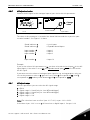
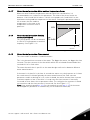
2.1.9 Start function
Ramp:
0 The frequency converter starts from 0 Hz and accelerates to maximum
frequency within the set
P2.8. (Load inertia or starting friction may cause
prolonged acceleration times).
Flying start:
1 The frequency converter is able to start into a running motor by applying a
small torque to motor and searching for the frequency corresponding to the
speed the motor is running at. The searching starts from the maximum
frequency towards the actual frequency until the correct value is detected.
Thereafter, the output frequency will be increased / decreased to the set
reference value according to the set acceleration/deceleration parameter
Use this mode if the motor is coasting when the start command is given. With
the flying start, it is possible to ride through short mains voltage interruptions.
Conditional flying start
2 With this mode it is possible to disconnect and connect the motor from the
frequency converter even when the Start command is active. On re-connecting
the motor, the drive will operate as described in selection 1
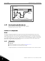
2.1.10 Stop function
Coasting:
0 The motor coasts to a halt without control from the frequency converter after
the Stop command.
Ramp:
1 After the Stop command, the speed of the motor is decelerated according to
the set deceleration parameters.
If the regenerated energy is high it may be necessary to use an external
braking resistor for faster deceleration.

1
Description of parameters vacon • 19
24-hour support: +358-40-8371 150 • Email: [email protected]
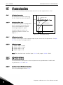
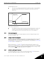
2.1.11 U/f optimisation
0 Not used
1 Automatic torque boost
The voltage to the motor changes automatically which makes the
motor produce sufficient torque to start and run at low
frequencies. The voltage increase depends on the motor type and
power. Automatic torque boost can be used in applications where
starting torque due to starting friction is high, e.g. in conveyors.
NOTE!
In high torque – low speed applications – it is likely that the motor
will overheat. If the motor has to run a prolonged time under these
conditions, special attention must be paid to cooling the motor. Use
external cooling for the motor if the temperature tends to rise too
high.
2.1.12 I/O Reference selection
Defines the selected frequency reference source when the drive is controlled from the
I/O terminal.
0 AI1 reference (terminals 2 and 3, e.g. potentiometer)
1 AI2 reference (terminals 4 and 5, e.g. transducer)
2 Keypad reference (parameter
3.2)
3 Reference from Fieldbus (FBSpeedReference)
4 Motor potentiometer reference
5 AI1/AI2 selection. Selection of AI2 is made programmable by DIN3 Function (
P2.1.16)
2.1.13 DIN2 function
This parameter has 9 selections. If digital input DIN2 need not be used, set the
parameter value to 0.
1 Start reverse
2 Reverse
3 Stop pulse
4 External fault
Contact closed: Fault is displayed and motor stopped when the input is active
5 External fault
Contact open: Fault is displayed and motor stopped when the input is not active
6 Run enable
Contact open: Start of motor disabled
Contact closed: Start of motor enabled
Coast stop if dropped during RUN
7 Door open low
8 Door open hold
Contact closed: door open hold switch on.

1
20 • vacon Description of parameters
Telephone: +358-201-2121 • Fax: +358-201-212 205
2.1. 14 DIN3 function
The parameter has 19 selections. If digital input DIN3 need not be used, set the param.
Value to 0.
1 Reverse
Contact open: Forward
Contact closed: Reverse
2 External fault
Contact closed: Fault is displayed and motor stopped when the input is active
3 External fault
Contact open: Fault is displayed and motor stopped when the input is not active
4 Fault reset
Contact closed: All faults reset
5 Run enable
Contact open: Start of motor disabled
Contact closed: Start of motor enabled
Coast stop if dropped during RUN
6 Door open low
7 Door open hold
8 DC braking command
Contact closed: In Stop mode, the DC braking operates until the contact is opened.
DC-braking current is about 10% of the value selected with
par. 2.4.3.
9 Motor potentiometer UP
Contact closed: Reference increases until the contact is opened.
10 Motor potentiometer DOWN.
Contact closed: Reference decreases until the contact is opened
11 Thermistor fault/warning input, NOTE! See NXL User’s Manual,
Chapter 6.2.4
Contact open: thermal fault/warning is active
12 I/O terminal
13 Fieldbus
14 AI1/AI2 select
15 Door close low
16 Door close hold
17 Fire mode
18 Safe enable
2.1.15 Automatic restart function
The automatic restart is taken into use with this parameter
0 = Disabled
1 = Enabled (3 automatic restarts, see par.
2.7.1 – 2.7.3)
Page is loading ...
Page is loading ...
Page is loading ...
Page is loading ...
Page is loading ...
Page is loading ...
Page is loading ...
Page is loading ...
Page is loading ...
Page is loading ...
Page is loading ...
Page is loading ...
Page is loading ...
Page is loading ...
Page is loading ...
Page is loading ...
Page is loading ...
Page is loading ...
Page is loading ...
Page is loading ...
Page is loading ...
Page is loading ...
Page is loading ...
Page is loading ...
Page is loading ...
Page is loading ...
Page is loading ...
Page is loading ...
Page is loading ...
Page is loading ...
-
 1
1
-
 2
2
-
 3
3
-
 4
4
-
 5
5
-
 6
6
-
 7
7
-
 8
8
-
 9
9
-
 10
10
-
 11
11
-
 12
12
-
 13
13
-
 14
14
-
 15
15
-
 16
16
-
 17
17
-
 18
18
-
 19
19
-
 20
20
-
 21
21
-
 22
22
-
 23
23
-
 24
24
-
 25
25
-
 26
26
-
 27
27
-
 28
28
-
 29
29
-
 30
30
-
 31
31
-
 32
32
-
 33
33
-
 34
34
-
 35
35
-
 36
36
-
 37
37
-
 38
38
-
 39
39
-
 40
40
-
 41
41
-
 42
42
-
 43
43
-
 44
44
-
 45
45
-
 46
46
-
 47
47
-
 48
48
-
 49
49
-
 50
50


Danfoss VACON NXL (Legacy Product) User guide
- Type
- User guide
- This manual is also suitable for
Ask a question and I''ll find the answer in the document
Finding information in a document is now easier with AI
Related papers
-
Vacon VACON® NXL PID Fire Mode ALFIFF32 User guide
-
-
-
-
-
-
Danfoss NXS/P Mech Brake Contr ASFIFF17V226 User guide
-
-
-
Vacon 20 User guide