Page is loading ...

COBRA-40 MKNO
E-1

2
ENGLISH

3
ENGLISH
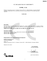
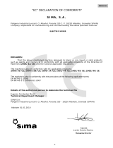
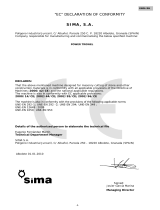
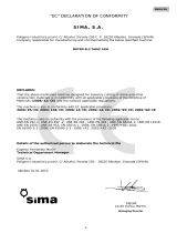
“CE” CONFORMITY DECLARATION
S I MA , S .A .
Polígono Industrial Juncaril, C/ Albuñol, Parcela 250 C. P. 18220 Albolote, Granada (ESPAÑA)
The company responsible for the manufacturing and set up of the following machine:
EXPANSION JOINT FLOOR SAW
DECLARATION:
That the aforementioned machine, for use in cutting expansion joints on concrete, asphalt and
other road surfaces, complies with all applicable CE directives (Directive 2006/42/CE) and
the corresponding Spanish laws..
The machine also complies with the following EU directives 2000/14/CE; 2002/44/CE;
2002/95/CE; 2002/96/CE
The machine also complies with the following directives
UNE-EN 292-1; UNE-EN 292-2; UNE-EN 294; UNE-EN 349; UNE-EN 500-1;
UNE-EN 13862:2002+A1=2009
UNE-EN 1050; UNE-EN 953
The licensed engineer responsible for the development of the machine
Eugenio Fernández Martín
Technical Supervisor
SIMA S.A.
Polígono Industrial Juncaril, C/ Albuñol, Parcela 250 - 18220 Albolote, Granada (ESPAÑA)
Albolote 26.09.2012
signed: Javier García Marina
Managing Director

4
ENGLISH
INDEX
E-1 ................................................................................................................ 1
“CE” CONFORMITY DECLARATION ................................................................ 3
1. GENERAL INFORMATION. .......................................................................... 5
2. GENERAL DESCRIPTION OF THE MACHINE . ¡ERROR! MARCADOR NO DEFINIDO.
2.1 PICTOGRAMS. ......................................................................................................... 6
3. TRANSPORTATION..................................................................................... 6
4. SET UP INSTRUCTIONS .............................. ¡ERROR! MARCADOR NO DEFINIDO.
4.1 HOW THE MACHINE ARRIVES .................................... ¡ERROR! MARCADOR NO DEFINIDO.
4.2 FITTING THE HANDLE / INSTALLING THE SHOCK ABSORBERS............................................ 7
4.3 ADJUSTING THE HANDLE. .......................................................................................... 7
4.4 ANTIVIBRATION HANDLE. .......................................................................................... 8
4.5 RAISING / LOWERING THE MACHINE TO CUT. ................................................................ 8
4.6 MOUNTING THE BLADE ............................................ ¡ERROR! MARCADOR NO DEFINIDO.
4.7 ADJUSTING THE REAR WHEEL AXLE ........................... ¡ERROR! MARCADOR NO DEFINIDO.
5. SAFETY RECCOMENDATIONS FOR THE MOTOR¡ERROR! MARCADOR NO
DEFINIDO.
6. STARTING AND USING THE MACHINE. ..................................................... 12
6.1 WATER TANK. ........................................................................................................ 12
6.2 ADD ON WATER TANK. ............................................................................................ 12
6.3 STARTING THE MACHINE. CONNECTING / DISCONNECTING. ........................................... 13
6.4 MAKING A CUT. ..................................................................................................... 14
6.5 SAFETY RECOMMENDATIONS. ................................................................................... 14
7. MAINTENANCE......................................................................................... 15
7.1 TIGHTENING OR REPLACEMENT OF THE TRANSMISSION BELTS. ....................................... 15
8. FREQUENTLY ASKED QUESTIONS ............... ¡ERROR! MARCADOR NO DEFINIDO.
9. TECHNICAL CHARACTERISTICS ................. ¡ERROR! MARCADOR NO DEFINIDO.
9.1 PERFORMANCE ...................................................... ¡ERROR! MARCADOR NO DEFINIDO.
10. GUARANTEE ........................................................................................... 18
11. SPARE PARTS .......................................... ¡ERROR! MARCADOR NO DEFINIDO.
11. PROTECTING THE ENVIRONMENT. ......................................................... 18
12. NOISE LEVEL DECLARATION. ................................................................. 18
13. MECHANICAL VIBRATION DECLARATION. .............................................. 18

5
ENGLISH
1. GENERAL INFORMATION.
IMPORTANT: READ AND UNDERSTAND THIS SET OF INSTRUCTIONS BEFORE ATTEMPTING TO OPERATE
THE MACHINE
SIMA S.A. thanks you for purchasing the COBRA floor saw.
This instruction manual gives you all necessary information to; get the machine started, use the machine,
maintain the machine, and if required, repair the machine. It also highlights the safety implications on the operator in
each of the aforementioned processes. If instructions are followed then operation will be safe and the machine will
require little maintenance.
For these reasons, it is obligatory for any operator or repairer of this machinery to read the instruction
manual.
It is advisable to keep this instruction manual near to where the machine is being operated for
easy reference.
2. GENERAL DESCRIPTION OF THE MACHINE
• Expansion joint floor saws are designed and manufactured for making cuts on horizontal surfaces of asphalt,
concrete, tiling and similar surfaces using high speed diamond blades, the COBRA floor saws are of the walk-
behind variety and as such should be pushed by the operator to make cuts in the floor surface. The blade is
cooled by water drawn from the tank; the machine can also be connected to mains water.
Any use of this machine for other purposes could be dangerous and is therefore prohibited.
The machine incorporates;
• Handle operated pitch control and shock absorbers with lock feature.
• Water tank, with option to connect cooling system to mains water.
• Emergency stop on the motor.
•
Flexible rubber tires and aluminium rims with double pillow block bearings
.
• Fitted with a blade guard and water cooling system.
• Cooling system has a socket that allows it to use mains water.
• The machine is powered by a combustion motor which can be accelerated by a lever on the engine.
• The chassis is painted with a resistant epoxy polyester paint which makes the machine resistant to rust.
• Machine is fitted with antisplash screen to avoid water from the cooling system being sprayed onto the rear
axle.
• Fitted with a guide line to indicate the cutting direction.
• Flexible pulley and belt system, all transmission is fully protected to avoid damage caused by dust water.
• The chassis has elevation holes to aid in loading / transporting the machine.
• The push handle is adjustable for the comfort of the operator.

6
ENGLISH
2.1 PICTOGRAMS.
The pictograms on the machine have the following meaning:
IT IS ESSENTIAL TO READ THE INSTRUCTION MANUAL.
THE USE OF HARD HAT, SAFETY GOGGLES AND AUDIO PROTECTION IS
ESSENTIAL.
THE USE OF GLOVES IS ESSENTIAL.
SAFETY SHOES MUST BE WORN.
DANGER, CUTTING AREA.
NO ACCESS FOR ANYONE NOT WORKING ON THE JOBSITE.
NO ACCESS FOR UNAUTHORIZED PEOPLE.
ELEVATION ZONE FOR THE MACHINE.
NOISE LEVEL GENERATED BY THE MACHINE.
3. TRANSPORTATION
When it comes to moving the machine over flat surfaces the COBRA floor saw can be manually pushed on its
own wheels having elevated the machine to its highest non cutting position.
For transport that requires the machine to be
elevated the machine has a hook eye at the top of the
machine for safe lifting. The weight and dimensions of
the machine allow for it to be transported on a light
loader.
DANGER: Use only lifting chains that can cope
with the weight of the machine (see specification sticker
on the machine). The machine must be lowered slowly so
as not to damage any of the components. The machine
should only be elevated from the lifting ring indicated on
the picture.

7
ENGLISH
4. SETUP INSTRUCTIONS
4.1 HOW THE MACHINE ARRIVES TO YOU
On opening up the packaging you will find the
following:
• Body of the machine with the handle unfitted.
The handle.
• Bag containing documentation and instruction manuals.
4.2 ATTACHING THE HANDLE / CONNECTING THE SHOCK ABSORBERS.
Given the ease of fitting and the advantage of reducing packing dimensions the handle is delivered unfitted. To
fit it slide it onto the protruding tube and fix it in place with the screw blots and the quick release hands provided.
Connect the cable that works the
shock absorbers in the manner
pictured.
4.3 ADJUSTING THE HEIGHT OF OF THE PUSH HANDLE.
Once the handle is correctly installed the height can be adjusted to the comfort of the user.
CHANGING THE HEIGHT OF THE PUSH HANDLE
1. Loosen the quick release handle
.
2. Remove the screw.
3. Change the position of the handle and reinsert the screw.
4. Tighten the quick release handle.

8
ENGLISH
4.4 ANTI VIBRATION HANDLE.
An antivibration handle is available which reduces vibrations and increases comfort for the user. The handle
minimizes fatigue and reduces injuries that can be caused by vibrations.
The handle bar is mounted on a silent block of soft rubber which
absorbs a lot of vibrations.
Changing the handle bar
1. Remove the screws that fix the handle bar in place.
2. Replace the handle bar.
3. Reinsert and fix the screws.
4.5 RAISING/ LOWERING TO CUT.
The machine raises and lowers using a gas shock absorber. This is activated by the lever located on the handle
bar.
RAISING THE MACHINE UP
1. Press the lever down all the way with your
thumb.
2. Press the handle bar down at the same time to
raise the cutting head.
3. When the desired height is reached release the
shock absorber lever and stop pushing down
on the handle bar..
LOWERING TO CUT.
1. Press the lever gently with your thumb to
gauge the downward movement of the
machine. Once the lever is fully depressed you
should assume the weight of the machine and
guide it down smoothly so that the machine is
not ´dropped ´and damaged.
2. To stop the raising and/or lowering process release the shock absorber lever.
ADVISE: Practice this a few times before you try to use the machine with a blade.
IMPORTANT: When a blade is mounted the lowering of the machine should be very smooth
until the blade contacts with the surface, once the blade is cutting the machine can be
lowered as normal.

9
ENGLISH
4.6 FITTING THE BLADE
You will always get better results by using the most appropriate blade for the surface you are cutting. The
blades are cooled by water. The cooling system guarantees the correct flow for the cooling of the disc.
Installing the blade.
1. Disconnect the refrigeration system.
2. Loosen the nut that holds the blade protection in place. The nut loosens in the same direction as the
movement of the blade.
3. Start with the hexagonal spanner to hold the nut in place and then use the rod to loosen as pictured.
4. Remove the bolt and the exterior flange and fit the blade against the inside flange.
5. Re-fit the exterior flange.
6. Put the disc protector back in its place and tighten the screws..
7. Reconnect the cooling system.
• The nut loosens in the same direction as the direction of the blade.
• Never start or use the machine without the blade protector fitted.
• Make sure that the blade cutting direction is correct. Match the arrow on the blade and the arrow on
the blade protector and make sure they are pointing the same way.
• Make sure that the blade is flush on the flange before tightening the screw.

10
ENGLISH
4.7 ADJUSTING THE REAR AXLE
The rear axle can be moved left and right., This is to allow the machine to avoid obstacles in the road while
maintaining a straight cut.
How to change the position of the axle.
1.
Loosen the quick release handle.
2.
Move the axle left and right and then retighten the handle when the axle is in place.
Only position the axle in a manner that ensures the stability of the machine

11
ENGLISH
5. SAFETY RECCOMENDATIONS FOR THE ENGINE
• Fill the petrol tank in a well-ventilated place and do not overfill.
• Avoid inhaling any fumes as you fill the tank.
• Avoid spilling fuel as it can be dangerous and flammable.
• Do not smoke while filling the tank. Store fuel away from naked flames.
• If petrol is spilt, clean it up and allow the fumes to evaporate before starting the motor..
• Don´t put any flammable material on the engine.
• Avoid contact between petrol and skin.
• Do not permit anyone to use the engine without the instruction manual nearby.
• Do not touch the engine when it is hot. It could cause burns to the skin.
• Do not let children or animals near the engine.
• Keep petrol out of the reach of children.
• Do not fill the tank or smoke while the machine is in operation.
WARNING: All guidelines in this manual must be adhered to as well as local health and safety
guidelines
The motors are supplied with oil but without fuel.
Before starting the engine , check the oil level using the dipstick while the machine is on flat ground, if
necessary fill the engine with the appropriate oil.

12
ENGLISH
6. INSTRUCTIONS FOR STARTING UP THE MACHINE.
6.1 WATER TANK.
The COBRA expansion joint saw has a
water tank cooling system that cools the blade
while the machine is in use. While filling the tank
close the valve.
6.2 OPTIONAL ADD-ON TANK.
For extra range an optional add-on tank is available.
Installation instructions.
1.
Fix the water tank onto the handle using the quick release handle.
2.
Close the valve and cut the refrigeration tube between the valve and the snap on connection.
3. Connect the additional fuel tank as shown in the picture.
ALWAYS CLOSE THE VALVE WHEN REFILLING THE TANK.

13
ENGLISH
USING THE SPARE WATER TANK.
When both tanks are filled, keep the front tank´s valve closed so that you are exclusively using the tank on
the handle.. If you don´t closet he valve the water will simply run from the handle tank to the front tank and will
overspill.
6.3 USING THE MACHINE CONNECTING/DISCONNECTING.
Starting the engine:
• Man oeuvre the machine so that the blade is a few centimeters from the floor surface.
• Turn the engine switch to ON
• Open the fuel valve.
• Open the choke. (Not necessary if the engine is warm or conditions are hot)
• Putt he gas lever in the slight acceleration position.
• Start the engine by pulling the starter cord.
• Let the engine warm up and then closet he choke adjust the gas lever depending on the revolutions
required for each project.
• To stop the motor turn the motor switch to the off position.
• Closet he fuel feed
For more details on operating the motor please refer to your instruction manual.

14
ENGLISH
6.4 MAKING A CUT.
Starting the motor:
1. Start the engine with the blade elevated above the cutting surface.
2. Position the machine in the direction you wish to cut, drop the metal cut guide.
3. Before you start cutting open the water valve, The blade should receive the correct amount of water to
be able to cool the blade down. A badly cooled blade will not last as long.
4. With the motor at maximum throttle, lower the machine until the blade achieves the desired cutting
depth. Push the machine forward slightly as you are doing this so that the initial cut is not exaggerated
5. Once the correct cutting depth is achieved, push the machine along the predetermined cutting line. The
speed of cut should not exceed the limitations of the blade based on depth of cut and the material being
cut. If the blade is trying to rise out of the groove it is due to excessive force.
Don´t try to correct cutting mistakes by forcing the machine as this will result in damaging the blade .
To stop the machine raise the blade up a few centimeters above the ground. Never stop the engine while
the blade is cutting.
If for any reason the machine is stopped while the blade is cutting, never try to start the machine again
while the blade is cutting. The blade should always be out of the ground when cutting.
This machine shouldn´t be used in the rain or the dark.
6.5 SAFETY RECCOMENDATIONS.
• The machine should only be used by experienced operators.
• Before using the machine read the safety instructions and make sure you comply with all safety regulations.
• Make sure that the machine you will use is in good working order.
• Don´t start the machine unless all the Green guards are in place.
• It is advisable to use safety goggles, protective boots and hearing protection. Always use safety equipment
that meets official standards..
• Only site employees to use the machine.
• Work clothing should not be loose as loose parts can get caught in the moving parts of the machine.
• When moving the machine always do so with the engine off.
• Before starting the engine make sure the blade isn´t touching the surface.
• Use the machine only in well ventilated areas as the machines gives off toxic gases.
• Do not touch the engine exhaust when the engine is on as it is very hot, even for a good few minutes after
use.
• Please also consider the safety procedures in the motors manual.
• Don´t use a pressure hose to clean the machine.
• At the end of the days use make sure the engine is completely switched off.
SIMA S.A. is not responsible for inappropriate use of this machine

15
ENGLISH
7. MAINTENANCE.
Maintenance should be carried out by technicians that are experience in these types of machines.
• Any engine maintenance should be carried out while the engine is off and cool.
• The technician should bear in mind the safety measures in this manual as well as the guidelines in the
motor´s manual.
• Grease the blade axle every 80 hours of use.
• Check oil level of the motor, always when the motor is horizontal.
• Use the oil recommended by the engine manufacturer.
• For all other maintenance instructions consult the engine manual.
• Clean the machine when necessary and if the machine starts to underperform have a technician look at it.
• Keep the shock absorber pillion clean.
• Don´t forget to remove all tools used for maintenance on the machine before restarting.
• Cover the machine in waterproof material when not in use.
• All modifications to the machine and use of unofficial spare parts are prohibited. SIMA S.A will not be held
responsible for any accidents or incidents caused by modifications made to the machine.
7.1 TIGHTENING OR CHANGING TRANSMISSION BELTS.
Transmission belts are parts that over time can become slack and fall below the permitted standards of
tightness. It is necessary to check the tightness of the belts periodically by performing a simple manual test by
prodding the belt with your finger to check the tightness, The ´give´
should be around 8mm.
The belts can also deteriorate through normal use so it may
be necessary to change the belt completely
Procedure to tighten the belt:
1. Remove the blade guard.
2. Loosen the 4 screws indicated in the picture here on the
right.
3. Use a flat spanner on the flange and tighten down as
shown in the picture. It will not require much force.
4. Tighten the four screws while keeping the flange in
place.
5. Replace the blade guard.
Changing the belt:
1. Loosen the flange screws and let the belt go loose.
2. Move the belt towards the outer rim of the pulley. Turn
the transmission while pushing the belt up and over
the lip to disconnect it.
IMPORTANT: The belts should be checked an
tightened after a full day (8hrs ) use. It is common for
the belt to stretch in the first 8 hrs of use. After this
period the stretching will stop and the belt will work
normally.

16
ENGLISH
8. FREQUENTLY OCCURING ISSUES
PROBLEM POSSIBLE CAUSE SOLUTION
Motor won ´t start
Low oil level alarm is activated
Add oil until the correct level is
reached
Fuel feed is closed
Open the valve
Motor switch in ´off ´position
Turn ´on´
Blade slows or stops while cutting
Insufficient acceleration
Put accelerator on higher setting
Loosen belts
Tighten belts
Moves forward too fast
Reduce accelerator
Incorrect blade being used
Use correct blade.
Motor not powerful enough
Have the motor serviced
Blade is wearing too quickly
Insufficient cooling Make sure the water is flowing
correctly
Machine moves too fast
Reduce throttle
Inapropriate blade
Use correct blade, specific to the
material you are cutting
Belts are wearing too quickly
Belts slip on the pulleys
Tighten belts
Lower throttle
Use appropriate blade for the surface
you are cutting.
Badly aligned belts Align the belts

17
ENGLISH
TECHNICAL SPECIFICATIONS
DATOS
COBRA-40
MKNO G13H
COBRA-50
MKNO G13H
COBRA-40
MKNO G14K
COBRA-50
MKNO G14K
MOTOR.
HONDA GX390 KHOLER CH440
FUEL.
Petrol Petroñ
MOTOR START.
Starter pull cord Starter pull cord
MAXIMUM POWER.
13HP/9,6KW 14HP/10,3KW
R.P.M. MOTOR.
3600 3600
MACHINE MOVEMENT.
Manual push Manual push
Ø MAX BLADE .
400mm / 15,7” 500mm / 20” 400mm / 15,7” 500mm / 20”
Ø .BLADE BORE
25,4mm / 1” 25,4mm / 1”
BLADE LOCATION.
Right hand side Right hand side
WATER TANK CAPACITY.
40 L / 10,56 Gl 40 L / 10,56 Gl
BLADE COOLING.
Both sides Both sides
NET WEIGHT.
89 Kg / 196 Lb 91 Kg / 200 Lb 89 Kg / 196 Lb 91 Kg / 200 Lb
CUTTING DEPTH REGULATION.
Shox Gas Shox Gas
DIMENSIONS L x W x H mm/
inch.
1380x716x979
54,33x28,18x38,54
1427x716x979
56,18x28,18x38,54
1380x716x979
54,33x28,18x38,54
1427x716x979
56,18x28,18x38,54
8.1 PERFORMANCE
Performance will vary depending on surfaces tested, type of blade used and the operator.
MODEL MOTOR POWER Cutting perfrmance
Cutting depth
during test
Ø Blade Material cut
COBRA-40
MKNO
13CV
140 cm/min.
5,51”/min.
10cm
3,93”
400
15,7”
Asphalt
103 cm/min.
5,51”/min.
Concrete
375 Kg/cm2
COBRA-40
MKNO
14CV
140 cm/min.
5,51”/min.
10cm
3,93”
400
15,7”
Asphalt
103 cm/min
5,51”/min.
Concrete
375 Kg/cm2

18
ENGLISH
9. GUARANTEE
SIMA, S.A. manufacturer of construction machinery, has a network of service centers, SERVÍ-SIMA. All repairs
carried out by agents in our network SERVÍ-SIMA, are subject to guidelines which will guarantee their quality.
SIMA. S.A. guarantees all ítems against manufacturing defects, bound by the conditions set out in our
CONDITIONS OF GUARANTEE.
Guarantees are invalidated if payment terms are not complied with.
SIMA S.A. reserves the right to alter its products and components without prior notice.
10. SPARE PARTS
All spare parts are identified in the spare parts diagram that cones along with this user manual .
To order any spare parts you should get in contact with SIMA´s aftersales department. And specify the
product code, as well as the model, serial number and year of manufacture that will all appear on the serial
number plate on the machine.
11. PROTECTING THE ENVIRONMENT.
All dust and residual byproducts should be cleaned up. All machines, spare parts, fluids and packaging
should all be correctly disposed of for recycling purposes.
R.A.E.E. Residuals resulting from electrical and electronic instruments have to be stored
into specific places for selective collection.
12. NOISE LEVEL DECLARATION.
Machine noise level whilst idling.
MODELO
COBRA MKNO G13H dec (dBa) 95
COBRA MKNO G14K dec (dBa) 95
13. VIBRATION LEVEL DECLARATION.
Exposure to vibration through the handle is :
MODEL FOR LEFT HAND m/ s² FOR RIGHT HAND m/ s²
COBRA MKNO G13H 0,00510968383 0,00223113067
COBRA MKNO G14K 0,00510968383 0,00223113067

19
ENGLISH
CERTIFICATE OF GUARANTEE AFTER-SALES SERVICE
COPY FOR END USER
MACHINE STICKER
NAME
ADDRESS
POSTAL CODE / TOWN
PROVINCE/ COUNTRY
Tel.: Fax:
e-mail
DATE OF PURCHASE
Signature and stamp of distributor/seller Signature of customer/end user
CONDITIONS OF GUARANTEE
1.) SIMA, S.A. guarantees against all manufacturing defects and is responsible for repairing the machine within one year of purchase, counting from the date
reflected in the obligatory CERTIFICATE OF GUARANTEE.
2.) The guarantee only covers labour and spare parts for the machine which is reflected in the CERTIFICATE OF GUARANTEE.
3.) All transport costs are excluded from claims as well as food expenses, accommodation, as well as transport costs of the machine to SIMA S.A., which will
be the responsibility of the client.
4.) The following can not be attributed to manufacturing defects:, dents caused by mistreatment, damage caused by dropping the machine, use of incorrect
voltage, incorrect installation and any other causes not relating to the product.
5.) GUARANTEE repairs can only be carried out by SIMA ora n authorised service agent for SIMA.
6.) This guarantee is invalidaded in the following circumstances:
a) Altering the Guarantee certificate once completed and signed.
b) When repairs have been carried out or spare parts replaced by un authorised service technicians.
c) When third party spare parts, not authorized by SIMA, S.A.
7.) SIMA S.A. takes no responsibility for damages caused by fault products. This includes damages for time, transport costs, telephone calls and personal or
company loss, as well as loss of salary or income.
8.) With regard to guarantee claims for motors during the 1 year period they should either be sent to SIMA or to an authorised repair agent for the engine in
question.
9.) SIMA should receive the guarantee certificate within no more tan 30 days from the date of purchase of the machine. To claim on guarantee the end user
will require a receipt of purchase with date, the guarantee form and the serial number of the machine .
SOCIEDAD INDUSTRIAL DE MAQUINARIA ANDALUZA, S.A.
POL. IND. JUNCARIL, C/ALBUÑOL, PARC. 250
18220 ALBOLOTE (GRANADA)
Telf.: 34 - 958-49 04 10 – Fax: 34 - 958-46 66 45
MANUFACTURING OF LIGHT CONSTRUCITON EQUIPMENT
SPAIN
BUYERS DETAILS
MACHINE DETAILS

20
ENGLISH
/
