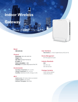
AP225W

Watchguard AP225W Hardware Guide

  • Hello! I am an AI chatbot trained to assist you with the Watchguard AP225W Hardware Guide. I’ve already reviewed the document and can help you find the information you need or explain it in simple terms. Just ask your questions, and providing more details will help me assist you more effectively!
WatchGuard
AP225W
Hardware Guide
AP225W
Wall Plate Access Point
About This Guide
Information in this guide is subject to change without notice. Companies, names, and data used in
examples herein are fictitious unless otherwise noted. No part of this guide may be reproduced or
transmitted in any form or by any means, electronic or mechanical, for any purpose, without the
express written permission of WatchGuard Technologies, Inc.
Guide revised: 3/9/2020
Copyright, Trademark, and Patent Information
Copyright © 1998 2020 WatchGuard Technologies, Inc. All rights reserved. All trademarks or trade names
mentioned herein, if any, are the property of their respective owners.
Complete copyright, trademark, patent, and licensing information can be found in the Copyright and
Licensing Guide, available online at https://www.watchguard.com/wgrd-help/documentation/overview.
About WatchGuard
WatchGuard® Technologies, Inc. is a global leader in network
security, providing best-in-class Unified Threat Management, Next
Generation Firewall, secure Wi-Fi, and network intelligence
products and services to more than 75,000 customers worldwide.
The company’s mission is to make enterprise-grade security
accessible to companies of all types and sizes through simplicity,
making WatchGuard an ideal solution for Distributed Enterprises
and SMBs. WatchGuard is headquartered in Seattle, Washington,
with offices throughout North America, Europe, Asia Pacific, and
Latin America. To learn more, visit WatchGuard.com.
For additional information, promotions and updates, follow
WatchGuard on Twitter, @WatchGuard on Facebook, or on the
LinkedIn Company page. Also, visit our InfoSec blog, Secplicity,
for real-time information about the latest threats and how to cope
with them at www.secplicity.org.
Address
505 Fifth Avenue South
Suite 500
Seattle, WA 98104
Support
www.watchguard.com/support
U.S. and Canada +877.232.3531
All Other Countries +1.206.521.3575
Sales
U.S. and Canada +1.800.734.9905
All Other Countries +1.206.613.0895
WatchGuard Technologies, Inc. i
Contents
WatchGuard AP225W Hardware Guide 1
APManagement 1
About Your Hardware 2
Hardware Specifications 2
Environmental Requirements 3
Hardware Description 4
Rear Panel Connections 4
Bottom Panel Connections 5
Device Indicators 6
Mount and Connect the AP 8
Attach the Mounting Bracket 8
Connect the AP 9
Attach the AP to the Mounting Bracket 11
Power Adapter (Optional) 12
Ethernet Power Injector (Optional) 13
Notices 15
Safety Warning 15
Power Adapter Requirements 15
FCC Certification 15
CENotice 16
Industry Canada Certification 16
EUDeclaration of Conformity 18
Brazil ANATEL 20
Mexico NOM 20
Japan Statement 20
Japan VCCIClass B Statement 20
ii WatchGuard Technologies, Inc.
Taiwan NCCStatement 20
Taiwan Class B Notice 21
RoHS Statement 21
WEEE Statement 21
REACH Certificate of Compliance 21
WatchGuard Technologies, Inc. iii
WatchGuard AP225W Hardware Guide
The WatchGuard AP225W is an enterprise-grade 2x2 MU-MIMO tri-radio 802.11ac wall plate access point
with dual concurrent 5 GHz and 2.4 GHz radios supporting 802.11a/n/ac Wave 2, 802.11b/g/n, two spatial
streams, and data rates of up to 876 Mbps and 400 Mbps, respectively. The AP225W also contains a third
2x2 MIMO 802.11ac radio for dedicated multi-function security and wireless network scanning.
APManagement
There are two ways you can manage your AP225W:
Total Wi-Fi and Secure Wi-Fi with WatchGuard Wi-Fi Cloud
A powerful cloud-based enterprise wireless management solution for AP configuration, security, and
monitoring.
Basic Wi-Fi with WatchGuard Firebox Gateway Wireless Controller
Local management, configuration, security, and monitoring of APs directly from your WatchGuard
Firebox. The WatchGuard Firebox requires Fireware v12.5.3 and higher.
WatchGuard Technologies, Inc. 1
About Your Hardware
Hardware Specifications
Hardware Description
Radio Type
and
Frequency
Band
n 2.4 GHz, 802.11b/g/n. Max data rate: 400 Mbps
n 5 GHz, 802.11a/n/ac. Max data rate: 867 Mbps
n Third radio for multi-purpose security and wireless network scanning
Antennas Six integrated omnidirectional antennas
Ethernet
Interfaces
n 1 x 10/100/1000 Mbps Gigabit Ethernet (PoE In LAN/Uplink) for wired LAN
connection through a switch or hub. This port also provides PoE (802.3af/at) power
for the device. The AP225W requires PoE+ (802.3at) for full functionality and
capabilities to enable power on the LAN3/PoE Out port.
n 2 x 10/100/1000 Mbps Gigabit Ethernet (LAN1, LAN2) for wired extension of an
SSID or a VLAN extension. Link aggregation is not supported.
n 1 x 10/100/1000 Mbps Gigabit Ethernet (LAN3 / PoE Out) for wired extension of an
SSID or a VLAN extension, and also provides PoE (802.3af) power to other
devices. The AP must be connected to PoE+ (802.3at) or DCpower to enable
power on the LAN3/PoE Out port. Link aggregation is not supported.
n 2 x pass-through ports for extension of the wired network.
Power
Interface
PoE In LAN/Uplink port (PoE+ 802.3at, PoE 802.3af), 48V
DC In:12V DC 2A
Power
Consumption
Maximum:12W
MTBF
(Mean Time
Between
Failures)
440,000+ hours at 40°C
Dimensions 186 mm X 124 mm X 25.4 mm (7.3 x 4.9” x 1”)
Weight 0.450 kg (1 lb)
WatchGuard AP225W Hardware Guide
2 WatchGuard Technologies, Inc.
WatchGuard AP225W Hardware Guide
Environmental Requirements
To safely install your WatchGuard AP, we recommend that you:
n Install the device indoors or outdoors, preferably under cover
n Make sure the device has adequate clearance for air flow and cooling
Other environmental requirements:
Operating Temperature 0°C to 40°C (32°F to 104°F)
Operating Humidity 0% to 95% non-condensing
Non-operating Temperature -20°C to 70°C (-4°F to 15F)
Non-operating Humidity 0% to 95%, non-condensing
WatchGuard Technologies, Inc. 3
Hardware Description
The AP has connections on both the rear panel and the bottom panel of the AP.
Rear Panel Connections
PASS-THROUGH
The pass-through port is a wired port that enables you to extend the wired network after the AP is
mounted on the wall. You can plug another device into the pass-through port on the bottom panel of
the AP. The pass-through ports on the rear panel and bottom panel of the AP are internally
connected. The traffic on the pass-through port does not interfere with AP traffic, and no policies can
be applied to pass-through port traffic.
POE In LAN/Uplink
This is an uplink LAN port that connects the AP to a wired LAN connection through a switch or hub.
This port also provides PoE (802.3af/802.3at) power for the AP.
WatchGuard AP225W Hardware Guide
4 WatchGuard Technologies, Inc.
WatchGuard AP225W Hardware Guide
Bottom Panel Connections
DC IN
If PoE power is unavailable, you can power the device with the optional 12V DC 2.5Apower adapter
(WG9009).
Pass-Through
The pass-through port is a wired port that enables you to extend the wired network after the AP is
mounted on the wall. You can plug another device into the pass-through port on the bottom panel of
the AP. The pass-through ports on the rear panel and bottom panel of the AP are internally
connected. The traffic on the pass-through port does not interfere with AP traffic, and no policies can
be applied to pass-through port traffic.
LAN3/PoE Out
Standard RJ45 connector that supports link speeds of 10/100/1000 Mbps. You can use this interface
as a wired extension of an SSID or a VLAN extension. This port can also provide PoE (802.3af)
power for another device. The AP must be connected to PoE+ (802.3at) or DCpower to enable
power on the LAN3/PoE Out port. Link aggregation is not supported.
The PoE Out port is intended to power small devices such as IP-based phones,
cameras, or other similar devices. WatchGuard recommends that you do not power
another access point from this port.
LAN2
Standard RJ45 connector that supports link speeds of 10/100/1000 Mbps. You can use this interface
as a wired extension of an SSID or a VLAN extension. Link aggregation is not supported.
WatchGuard Technologies, Inc. 5
LAN1
Standard RJ45 connector that supports link speeds of 10/100/1000 Mbps. You can use this interface
as a wired extension of an SSID or a VLAN extension. Link aggregation is not supported.
Reset Button
Resets the AP to factory-default settings.
n Use a paper clip or other small object to press the reset button through the hole.
n Press and hold the reset button for up to 10 seconds until all LEDs go off to indicate that the AP
has rebooted.
Device Indicators
The AP225W has these LED indicators:
WatchGuard AP225W Hardware Guide
6 WatchGuard Technologies, Inc.
WatchGuard AP225W Hardware Guide
This table provides detailed information about the device indicators:
LED Status Description
Power Off Powered off
Solid Green Powered on
Flashing
Green
APcannot connect to Wi-Fi Cloud or the Gateway Wireless
Controller
Flashing
Amber
APdid not receive an IP address from the DHCPserver
Uplink (PoE
In)
Off No Ethernet link.
Solid Green Connected to the network.
LAN1/2/3 Off No Ethernet link.
Solid Green
(Wi-Fi Cloud
mode)
A LAN interface is configured for a wireless extension, VLAN
extension, or link aggregation.
Solid Green
(Local mode)
A LAN interface is connected to the network.
2.4 GHz Off Wireless radio is inactive
Solid Green Wireless radio is active with a configured SSID
5 GHz Off Wireless radio is inactive
Solid Green Wireless radio is active with a configured SSID
Third Radio
(WIPS)
Off Wireless radio is inactive
Solid Green WIPSscanning is active (Wi-Fi Cloud mode only)
WatchGuard Technologies, Inc. 7
Mount and Connect the AP
Your package includes the AP225W, mounting bracket, and mounting screws.
The MAC address and serial number of your AP are printed on a label on the back of the
device. Make sure you record this information before you mount the AP.
Attach the Mounting Bracket
Use the included screws to attach the mounting bracket to an existing wall plate, or to a wall without an
existing wall plate.
Note: If your existing wall plate has female RJ45 connections, you must either re-terminate the Ethernet
cable with a male RJ45 connector, or use a bridge Ethernet cable between the female connectors on your
existing cables and the back of the AP if there is enough room in the wall junction box.
WatchGuard AP225W Hardware Guide
8 WatchGuard Technologies, Inc.
WatchGuard AP225W Hardware Guide
Connect the AP
Connect the Ethernet cables to the appropriate ports on the rear panel of the AP.
To power the APwith a PoE power source and connect the AP to your network:
n Plug one end of the Ethernet cable from your network into the POE In LAN/Uplink port on the rear
panel of the AP225W. Make sure the other end of the Ethernet cable is connected to your network
through a hub, switch, or injector with PoE power enabled.
n Connect an optional Ethernet cable from your network into the PASS-THROUGH port on the rear
panel of the AP225W.
WatchGuard Technologies, Inc. 9
To power the AP with the optional 12V DCpower adapter and connect the AP to your network:
n Plug the optional 12V power adapter into the DC IN power port on the bottom panel of the AP225W,
then plug the power adapter into an AC power source.
n To connect the AP225W to the network, connect an Ethernet cable into the POE In LAN/Uplink port
on the rear panel of the AP. Make sure the other end of the Ethernet cable is connected to your network
through a hub or switch.
n Connect an optional Ethernet cable from your network into the PASS-THROUGH port on the rear
panel of the AP225W.
WatchGuard AP225W Hardware Guide
10 WatchGuard Technologies, Inc.
WatchGuard AP225W Hardware Guide
Attach the AP to the Mounting Bracket
To attach the AP to the mounting bracket:
1. Align the tabs on the bracket with the slots on the rear panel of the AP, then slide the AP onto the
bracket.
2. Attach the AP to the bracket with the included screw.
WatchGuard Technologies, Inc. 11
Power Adapter (Optional)
An optional AC power adapter supplies 12V DC power to the AP.
AC Power Adapter Specs
WatchGuard Part Number WG9009
AC Input Voltage Rating 100-240V, 50-60Hz
Output Voltage DC 12V, 2.5A
Region Specific Adapter Plugs US, UK, AU/NZ, EMEA
Temperature Operating: 0 - 40°C (32 10F)
Storage: -20 - 8C (-4 185°F)
Humidity Operating: 5% 95%
Storage: 0% 95%
Dimensions 69 mm x 32.6 mm x 49.5 mm (2.7" x 1.28" x 1.5")
WatchGuard AP225W Hardware Guide
12 WatchGuard Technologies, Inc.
WatchGuard AP225W Hardware Guide
Ethernet Power Injector (Optional)
You can power the AP with an optional Ethernet Power Injector. The PoE+ power injector enables you to
power the AP through an existing Ethernet connection. With this device, you do not have to position your
AP near a power outlet.
This device complies with IEEE 802.3at/af PoE specifications. Do not use any PoE
adapters that are not IEEE 802.3at/af compliant as they may damage your device.
To connect an Ethernet Power Injector to the WatchGuard AP:
1. Plug the Ethernet Power Injector into an AC power source.
2. Connect an Ethernet cable from your network backbone (for example, a PoE-capable router, switch, or
hub) to the LAN connector on the Ethernet Power Injector.
3. Connect an Ethernet cable from the LAN1 PoE Ethernet interface on the AP to the PoE connector on
the Ethernet Power Injector.
The table provides the specifications for the power adapter.
Ethernet Power Injector Specs
WatchGuard
Part Number
802.3at PoE+ Injector with AC cord (US/FCC) (WG8599)
802.3at PoE+ Injector with AC cord (CE) (WG8600)
802.3at PoE+ Injector with AC cord (UK) (WG8601)
802.3at PoE+ Injector with AC cord (AUS) (WG8602)
Specification IEEE 802.3at/af
AC Input
Voltage
Rating
100-240 VAC
Input Current 0.8A max for 100VAC
WatchGuard Technologies, Inc. 13
Ethernet Power Injector Specs
Output
Power
30W max
Ethernet
Interfaces
LAN: RJ-45 for 10/100/1000 Mbps data
POE: RJ-45 for 10/100/1000 Mbps data and power
Voltage: Pin4, 5:54V, Pin7, 8:Return
Indicator Power: Green
Temperature Operating: 0 - 40°C (32 10F)
Storage: -30 - 8C (-22 17F)
Humidity Operating: 5% 90%
Storage: 5% 90%
Dimensions 99 mm x 68.5 mm x 33 mm (3.9" x 2.27"x 1.3")
Weight 0.33 lbs(149.6 g)
WatchGuard AP225W Hardware Guide
14 WatchGuard Technologies, Inc.
WatchGuard AP225W Hardware Guide
Notices
All WatchGuard products are designed and tested to meet strict safety requirements. These requirements
include product safety approvals and other global compliance standards. Please read these instructions
carefully before operating the product, and refer to them as needed to ensure the continued safe operation of
your product.
For patent information, please visit http://www.watchguard.com/patents
Safety Warning
If protective earthing is used as a safeguard, the instructions shall require connection of the equipment
protective earthing conductor to the installation protective earthing conductor (for example, by means of a
power cord connected to a socket-outlet with earthing connection). To meet safety and electromagnetic
interference (EMI) requirements, you must make sure the power source is connected to earth ground before
you connect power to the AP.
Power Adapter Requirements
This product is intended to be supplied by a Listed Power Adapter or DC power source marked “L.P.S. (or
Limited Power Source or PS2) rated 12V DC, 2A minimum, maximum ambient temperature (Tma)=4C, or
supplied by a Listed PoE Adapter marked “L.P.S. (or Limited Power Source or PS2) rated 54V DC, 0.6A
minimum, maximum ambient temperature (Tma)=4C. For more information regarding approved power
sources, please contact WatchGuard Technologies.
FCC Certification
This device complies with part 15 of the FCC Rules. Operation is subject to the following two conditions: (1)
This device may not cause harmful interference, and (2) this device must accept any interference received,
including interference that may cause undesired operation.
This equipment has been tested and found to comply with the limits for a Class B digital device, pursuant to
part 15 of the FCC Rules. These limits are designed to provide reasonable protection against harmful
interference in a residential installation.
This equipment generates, uses and can radiate radio frequency energy and, if not installed and used in
accordance with the instructions, may cause harmful interference to radio communications. However, there
is no guarantee that interference will not occur in a particular installation. If this equipment does cause
harmful interference to radio or television reception, which can be determined by turning the equipment off
and on, the user is encouraged to try to correct the interference by one or more of the following measures:
n Reorient or relocate the receiving antenna.
n Increase the separation between the equipment and receiver.
n Connect the equipment into an outlet on a circuit different from that to which the receiver is
n connected.
n Consult the dealer or an experienced radio/TV technician for help.
WatchGuard Technologies, Inc. 15
* FCC Caution: Any changes or modifications not expressly approved by the party responsible for
compliance could void the user’s authority to operate this equipment.
This transmitter must not be co-located or operating in conjunction with any other antenna or transmitter.
The device is for indoor use only. Supported in 2412-2462, 5180~5240, 5260~5320, 5500~5700,
5745~5825MHz and operation in the 2412-2462, 5180~5240, 5260~5320, 5500~5700, 5745~5825MHz band
are restricted to indoor usage only.
This device meets all the other requirements specified in Part 15E, Section 15.407 of the FCC Rules.
Radiation Exposure Statement:
This equipment complies with FCC radiation exposure limits set forth for an uncontrolled environment. This
equipment should be installed and operated with minimum distance 23cm between the radiator & your body
CENotice
The CE symbol on your WatchGuard Technologies equipment indicates that it is in compliance with the
Electromagnetic Compatibility (EMC) directive and the Low Voltage Directive (LVD) of the European Union
(EU).
Industry Canada Certification
This device complies with ISED’s licence-exempt RSSs. Operation is subject to the following two
conditions: (1) This device may not cause harmful interference, and (2) this device must accept any
interference received, including interference that may cause undesired operation.
Le présent appareil est conforme aux CNR d’ ISED applicables aux appareils radio exempts de licence.
Lexploitation est autorisée aux deux conditions suivantes: (1) le dispositif ne doit pas produire de brouillage
pjudiciable, et (2) ce dispositif doit accepter tout brouillage reçu, y compris un brouillage susceptible de
provoquer un fonctionnement indésirable.
Caution
(i) the device for operation in the band 5150-5250 MHz is only for indoor use to reduce the potential for
harmful interference to co-channel mobile satellite systems;
(ii) where applicable, antenna type(s), antenna models(s), and worst-case tilt angle(s) necessary to remain
compliant with the e.i.r.p. elevation mask requirement set forth in section 6.2.2.3 shall be clearly indicated.
Avertissement
Le guide d’utilisation des dispositifs pour seaux locaux doit inclure des instructions précises sur les
restrictions susmentionnées, notamment :
WatchGuard AP225W Hardware Guide
16 WatchGuard Technologies, Inc.
/