En-1
1. SAFETY PRECAUTIONS
1.1. IMPORTANT! Please read before starting
This air conditioning system meets strict safety and operating standards.
As the installer or service person, it is an important part of your job to install or service the
system so it operates safely and efficiently.
For safe installation and trouble-free operation, you must:
• Carefully read this instruction booklet before beginning.
• Follow each installation or repair step exactly as shown.
• Observe all local, state, and national electrical codes.
• Pay close attention to all danger, warning, and caution notices given in this manual.
WARNING:
This symbol refers to a hazard or unsafe practice which can result in
severe personal injury or death.
CAUTION:
This symbol refers to a hazard or unsafe practice which can result in
personal injury and the potential for product or property damage.
• Hazard alerting symbols
: Electrical : Safety/alert
If Necessary, Get Help
These instructions are all you need for most installation sites and maintenance conditions.
If you require help for a special problem, contact our sales/service outlet or your certified
dealer for additional instructions.
In Case of Improper Installation
The manufacturer shall in no way be responsible for improper installation or maintenance
service, including failure to follow the instructions in this document.
1.2. SPECIAL PRECAUTIONS
When Wiring
ELECTRICAL SHOCK CAN CAUSE SEVERE PERSONAL INJURY OR DEATH. ONLY A
QUALIFIED, EXPERIENCED ELECTRICIAN SHOULD ATTEMPT TO WIRE THIS SYSTEM.
• Do not supply power to the unit until all wiring and tubing are completed or reconnected
and checked.
• Highly dangerous electrical voltages are used in this system. Carefully refer to the wir-
ing diagram and these instructions when wiring. Improper connections and inadequate
earthing (grounding) can cause accidental injury or death.
• Earth (Ground) the unit following local electrical codes.
• Connect all wiring tightly. Loose wiring may cause overheating at connection points and
a possible fi re hazard.
When Transporting
Be careful when picking up and moving the indoor and outdoor units. Get a partner to
help, and bend your knees when lifting to reduce strain on your back. Sharp edges or thin
aluminum fi ns on the air conditioner can cut your fi ngers.
When Installing...
...In a Ceiling or Wall
Make sure the ceiling/wall is strong enough to hold the unit’s weight. It may be necessary
to construct a strong wood or metal frame to provide added support.
...In a Room
Properly insulate any tubing run inside a room to prevent “sweating” that can cause
dripping and water damage to walls and fl oors.
...In an Area with High Winds
Securely anchor the outdoor unit down with bolts and a metal frame.
Provide a suitable air baffl e.
...In a Snowy Area (for Heat Pump-type Systems)
Install the outdoor unit on a raised platform that is higher than drifting snow.
When Connecting Refrigerant Tubing
• Keep all tubing runs as short as possible.
• Use the fl are method for connecting tubing.
• Apply refrigerant lubricant to the matching surfaces of the fl are and union tubes before
connecting them, then tighten the nut with a torque wrench for a leak-free connection.
• Check carefully for leaks before opening the refrigerant valves.
When Servicing
• Turn the power OFF at the main circuit breaker panel before opening the unit to check or
repair electrical parts and wiring.
• Keep your fi ngers and clothing away from any moving parts.
• Clean up the site after you fi nish, remembering to check that no metal scraps or bits of
wiring have been left inside the unit being serviced.
• After installation, explain correct operation to the customer, using the operating manual.
DANGER
Never touch electrical components immediately after the power supply has been turned
off. Electrical shock may occur. After turning off the power, always wait 5 minutes or
more before touching electrical components.
• Be sure to read this Manual thoroughly before installation.
• The warnings and precautions indicated in this Manual contain important information
pertaining to your safety. Be sure to observe them.
• Hand this Manual, together with the Operating Manual to the customer.
• Request the customer to keep them on hand for future use, such as for relocating or
repairing the unit.
WARNING
Request your dealer or a professional installer to install the unit in accordance with this
Manual.
An improperly installed unit can cause serious accidents such as water leakage, electric
shock, or fire.
If the unit is instruction in disregard of the instructions in the Installation Manual, it will
void the manufacturer’s warranty.
Do not turn ON the power until all work has been completed.
Turning ON the power before the work is completed can cause serious accidents such
as electric shock or fire.
If refrigerant leaks while work is being carried out, ventilate the area.
If the refrigerant comes in contact with a flame, it produces a toxic gas.
Installation must be performed in accordance with the requirement of NEC (National
Electrical Code) and CEC (Canadian Electrical Code) by authorized personnel only.
Except for EMERGENCY, never turn off main as well as sub breaker of the indoor units
during operation. It will cause compressor failure as well as water leakage. First, stop
the indoor unit by operating the control unit, converter or external input device and then
cut the breaker.
Make sure to operate through the control unit, converter or external input device.
When the breaker is designed, locate it at a place where the users cannot start and stop
in the daily work.
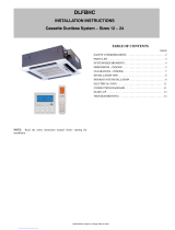
INSTALLATION MANUAL
PART No. 9371022581-02
VRF system indoor unit (Cassette type)
Contents
1. SAFETY PRECAUTIONS .........................................................................................1
1.1. IMPORTANT! Please read before starting ........................................................1
1.2. SPECIAL PRECAUTIONS ................................................................................1
2. ABOUT THIS PRODUCT..........................................................................................2
2.1. Precautions for using the R410A refrigerant ..................................................... 2
2.2. Special tool for R410A ...................................................................................... 2
2.3. Accessories ...................................................................................................... 2
2.4. Optional parts ...................................................................................................2
2.5. About unit of the length ..................................................................................... 2
3. INSTALLATION WORK ............................................................................................ 3
3.1. Selecting an installation location ....................................................................... 3
3.2. Installation dimensions .....................................................................................3
3.3. Discharge direction setting ...............................................................................3
3.4. Installing the unit ............................................................................................... 3
4. PIPE INSTALLATION ............................................................................................... 4
4.1. Selecting the pipe material ...............................................................................4
4.2. Pipe requirement ..............................................................................................4
4.3. Flare connection (pipe connection) ................................................................... 4
4.4. Installing heat insulation ...................................................................................5
5. INSTALLING DRAIN PIPES ..................................................................................... 5
6. ELECTRICAL WIRING .............................................................................................6
6.1. Electrical requirement .......................................................................................6
6.2. Wiring method ...................................................................................................7
6.3. Unit wiring .........................................................................................................7
6.4. Connection of wiring .........................................................................................8
6.5. Optional parts wiring .........................................................................................9
6.6. External input and external output (Optional parts) .......................................... 9
7. FIELD SETTING ..................................................................................................... 11
7.1. Setting the address ......................................................................................... 11
7.2. Custom code setting ....................................................................................... 11
7.3. Function setting ..............................................................................................12
8. CASSETTE GRILLE INSTALLATION .....................................................................13
8.1. Remove the intake grille .................................................................................13
8.2. Install cassette grille to indoor unit .................................................................. 13
8.3. Attach the intake grille ....................................................................................14
9. TEST RUN ..............................................................................................................14
9.1. Test run using Outdoor unit (PCB) ..................................................................14
9.2. Test run using Outdoor unit (PCB) ..................................................................14
10. CHECK LIST ...........................................................................................................14
11. ERROR CODES ..................................................................................................... 14