Page is loading ...

INSTALLATION INSTRUCTIONS
Single Split System Air Conditioner
This air conditioner uses the refrigerant R410A.
NOTE
External diameter of service port R410A: 5/16"
Remote Controllers
Timer Remote Controller (wired) CZ-RTC2 Timer Remote Controller comes with Instructions Manual.
Wireless Remote Controller
CZ-RWSU1U for U1 and T1 type Indoor units
CZ-RWSC1U for F1 type Indoor units
CZ-RWSK1U for K1 type Indoor units
Units should be installed by licensed contractor according to
local code requirements.
85464369532012
Model No.
Indoor Units
Type Indoor Unit Type 26 36 42 Remarks
U1 4-Way Cassette
S-26PU1U6
(CZ-24KPU1U)**
S-36PU1U6
(CZ-36KPU1U)**
S-42PU1U6
(CZ-36KPU1U)**
with Wired Remote Controller: CZ-RTC2
K1 Wall Mounted S-26PK1U6 with Wireless Remote Controller: CZ-RWSK1U
T1 Ceiling S-26PT1U6 S-36PT1U6 S-42PT1U6 with Wired Remote Controller: CZ-RTC2
F1 Low Silhouette Duct S-26PF1U6 S-36PF1U6 with Wired Remote Controller: CZ-RTC2
** Panel (optional parts)
CV6233186962

2
IMPORTANT!
Please Read Before Starting
This air conditioning system meets strict safety and oper-
ating standards. As the installer or service person, it is an
important part of your job to install or service the system so
it operates safely and efficiently.
For safe installation and trouble-free operation, you must:
Carefully read this instruction booklet before beginning.
Follow each installation or repair step exactly as shown.
Observe all local, state, and national electrical codes.
Pay close attention to all warning and caution notices
given in this manual.
This symbol refers to a hazard or
unsafe practice which can result
in severe personal injury or death.
This symbol refers to a hazard or
unsafe practice which can result
in personal injury or product or
property damage.
If Necessary, Get Help
These instructions are all you need for most installation
sites and maintenance conditions. If you require help for a
special problem, contact our sales/service outlet or your
certified dealer for additional instructions.
In Case of Improper Installation
The manufacturer shall in no way be responsible for
improper installation or maintenance service, including fail-
ure to follow the instructions in this document.
SPECIAL PRECAUTIONS
WARNING
When Wiring
ELECTRICAL SHOCK CAN CAUSE
SEVERE PERSONAL INJURY OR DEATH.
ONLY A QUALIFIED, EXPERIENCED
ELECTRICIAN SHOULD ATTEMPT TO
WIRE THIS SYSTEM.
•
are completed or reconnected and checked.
•
Do not supply power to the unit until all wiring and tubing
Highly dangerous electrical voltages are used in this
system. Carefully refer to the wiring diagram and these
instructions when wiring. Improper connections and inad-
equate grounding can cause accidental injury or death.
• Ground the unit following local electrical codes.
• Connect all wiring tightly. Loose wiring may cause over-
heating at connection points and a possible fire hazard.
• To prevent possible hazards from insulation failure,
the unit must be grounded.
When Transporting
Be careful when picking up and moving the indoor and
outdoor units. Get a partner to help, and bend your knees
when lifting to reduce strain on your back. Sharp edges or
thin aluminum fins on the air conditioner can cut your
fingers.
When Installing…
…In a Room
Properly insulate any tubing run inside a room to prevent
Select an installation location which is rigid and strong
enough to support or hold the unit, and select a location
for easy maintenance.
“sweating” that can cause dripping and water damage to
walls and floors.
Keep the fire alarm and the air outlet at least
5 feet away from the unit.
…In Moist or Uneven Locations
Use a raised concrete pad or concrete blocks to provide
a solid, level foundation for the outdoor unit. This prevents
water damage and abnormal vibration.
…In an Area with High Winds
Securely anchor the outdoor unit down with bolts and a
metal frame. Provide a suitable air baffle.
…In a Snowy Area (for Heat Pump-type Systems)
Install the outdoor unit on a raised platform that is higher
than drifting snow. Provide snow vents.
When Connecting Refrigerant Tubing
•
gas leaks during the installation. Be careful not to allow
contact of the refrigerant gas with a flame as this will
cause the generation of poisonous gas.
•
•
•
the flare and union tubes before connecting them, then
tighten the nut with a torque wrench for a leak-free con-
nection.
•
•
Ventilate the room well, in the event that is refrigerant
Keep all tubing runs as short as possible.
Use the flare method for connecting tubing.
Apply refrigerant lubricant to the matching surfaces of
Check carefully for leaks before starting the test run.
• Do not leak refrigerant while piping work for an installation
or re-installation, and while repairing refrigeration parts.
Handle liquid refrigerant carefully as it may cause frostbite.
WARNING
CAUTION
CAUTION
When performing piping work do not
mix air except for specifled refrigerant
(R410A) in refrigeration cycle. It
causes capacity down, and risk of
explosion and injury due to high
tension inside the refrigerant cycle.
•
Refrigerant gas leakage may cause
fire.
•
Do not add or replace refrigerant
other than specified type.
It may cause product damage,
burst and injury etc.
WARNING

3
Check of Density Limit
The room in which the air conditioner is to be
installed requires a design that in the event of refrig-
erant gas leaking out, its density will not exceed a set
limit.
The refrigerant (R410A), which is used in the air condition-
er, is safe, without the toxicity or combustibility of ammonia,
and is not restricted by laws imposed to protect the ozone
layer. However, since it contains more than air, it poses the
risk of suffocation if its density should rise excessively. Suf-
focation from leakage of refrigerant is almost non-existent.
With the recent increase in the number of high density
buildings, however, the installation of multi air conditioner
systems is on the increase because of the need for effec-
tive use of floor space, individual control, energy conserva-
tion by curtailing heat and carrying power, etc.
Most importantly, the multi air conditioner system is able
to replenish a large amount of refrigerant compared to
conventional individual air conditioners. If a single unit of
the multi air conditioner system is to be installed in a
small room, select a suitable model and installation pro-
cedure so that if the refrigerant accidentally leaks out, its
density does not reach the limit (and in the event of an
emergency, measures can be made before injury can
occur).
ASHRAE and the International Mechanical Code of the
ICC as well as CSA provide guidance and define safe-
guards related to the use of refrigerants, all of which define
a Refrigerant Concentration Level (RCL) of 25 pounds
per 1,000 cubic feet for R410A refrigerant.
For additional guidance and precautions related to
refrigerant safety, please refer to the following documents:
International Mechanical Code 2009 (IMC-2009)
(or more recently revised)
ASHRAE 15
ASHRAE 34
When Servicing
• Turn the power OFF at the main power box (mains)
before opening the unit to check or repair electrical
parts and wiring.
•
•
Keep your fingers and clothing away from any moving
parts.
Clean up the site after you finish, remembering to check
that no metal scraps or bits of wiring have been left
inside the unit being serviced.
•
•
Do not touch the air inlet or the
sharp aluminum fins of the
outdoor unit. You may get injured.
• Ventilate any enclosed areas when
installing or testing the refrigeration
system. Escaped refrigerant gas, on
contact with fire or heat, can produce
dangerously toxic gas.
Confirm after installation that no
refrigerant gas is leaking. If the gas
comes in contact with a burning stove,
gas water heater, electric room heater
or other heat source, it can cause the
generation of poisonous gas.
WARNING
• Do not clean inside the indoor and
outdoor units by users. Engage
authorized dealer or specialist for
cleaning.
• In case of malfunction of this
appliance, do not repair by yourself.
Contact to the sales dealer or service
dealer for a repair.
CAUTION
CAUTION
Others
•
•
•
Do not touch the air inlet or the
sharp aluminum fins of the
outdoor unit. You may get injured.
Do not sit or step on the unit,
you may fall down accidentally.
Do not stick any object into the
FAN CASE.
You may be injured and the
unit may be damaged.
NOTICE
• This device complies with part 15 of the FCC Rules.
Operation is subject to the following two conditions:
(1) This device may not cause harmful interference, and (2) this device must accept any interference
received, including interference that may cause undesired operation.
• This equipment has been tested and found to comply with the limits for a Class B digital device,
pursuant to part 15 of the FCC Rules.
These limits are designed to provide reasonable protection against harmful interference in a residential
installation. This equipment generates, uses and can radiate radio frequency energy and, if not installed
and used in accordance with the instructions, may cause harmful interference to radio communications.
However, there is no guarantee that interference will not occur in a particular installation. If this
equipment does cause harmful interference to radio or television reception, which can be determined
by turning the equipment off and on, the user is encouraged to try to correct the interference by one or
more of the following measures:
• Reorient or relocate the receiving antenna.
• Increase the separation between the equipment and receiver.
• Connect the equipment into an outlet on a circuit different from that to which the receiver is connected.
• Consult the dealer or an experienced radio/TV technician for help.
• FCC Caution: To assure continued compliance, follow the attached installation instructions.
Any changes or modifications not expressly approved by the party responsible for compliance could
void the user’s authority to operate this equipment.

4
R407C tools
Item compatible Remarks
with R410A?
Manifold gauge Yes No Types of refrigerant, refrigerating machine oil, and
pressure gauge are different.
Charge hose Yes No To resist higher pressure, material must be changed.
Vacuum pump Yes Yes Use a conventional vacuum pump if it is equipped
with a check valve. If it has no check valve,
purchase and attach a vacuum pump adapter.
Leak detector Yes No Leak detectors for CFC and HCFC that
react to chlorine do not function because
R410A contains no chlorine. Leak detector
for HFC134a can be used for R410A.
Flaring oil Yes No For systems that use R22, apply mineral oil (Suniso oil)
to the flare nuts on the tubing to prevent refrigerant
leakage. For machines that use R407C or R410A, apply
synthetic oil (ether oil) to the flare nuts.
1-2. Prevent impurities including water, dust and oxide from entering the tubing. Impurities can cause R410A
refrigerant deterioration and compressor defects. Due to the features of the refrigerant and refrigerating
machine oil, the prevention of water and other impurities becomes more important than ever.
2. Be sure to recharge the refrigerant only in liquid form.
2-1. Since R410A is a non-azeotrope, recharging the refrigerant in gas form can lower performance and cause
defects of the unit.
2-2. Since refrigerant composition changes and performance decreases when gas leaks, collect the remaining
refrigerant and recharge the required total amount of new refrigerant after fixing the leak.
3. Different tools required
3-1. Tool specifications have been changed due to the characteristics of R410A.
Some tools for R22- and R407C-type refrigerant systems cannot be used.
Unit: inch
Material O
Copper tube
Outer diameter 1/4 3/8 1/2 5/8
Wall thickness t0.032 t0.032 t0.032 t0.04
Precautions for Installation Using New Refrigerant
1. Care regarding tubing
1-1. Process tubing
Material: Use C1220 phosphorous deoxidized copper specified in JIS H3300 “Copper and Copper Alloy Seam-
less Pipes and Tubes.”
Tubing size: Be sure to use the sizes indicated in the table below.
Use a tube cutter when cutting the tubing, and be sure to remove any flash. This also applies to distribution
joints (optional).
When bending tubing ø5/8" or smaller, use a bending radius that is 4 times the outer diameter of the tubing or larger.
* Using tools for R22 and R407C and new tools for R410A together can cause defects.
Manifold gauge
Vacuum pump
Outlet
Inlet
CAUTION
Use sufficient care in handling the tubing. Seal the tubing ends with
caps or tape to prevent dirt, moisture, or other foreign substances
from entering. These substances can result in system malfunction.
New
tool?

5
3-2. Use R410A exclusive cylinder only.
When charging with a refrigerant cylinder, use an
electronic scale for charging refrigerant. In this
case, if the volume of refrigerant in the cylinder
becomes less than 20% of the fully-charged
amount, the composition of the refrigerant starts
to change. Thus, do not use the refrigerant if the
amount in the charging cylinder is less than 20%.
Also, charge the minimum necessary amount to
the charging cylinder before using it to charge the
air conditioning unit.
Valve
Single valve
Charge liquid refrigerant with
cylinder in up-side-down position.
Single valve (with siphon tube)
Charge with cylinder in normal position.
Liquid
Valve
Liquid
Configuration and characteristics of cylinders
Fig. 1
Fig. 2

6
Page
CONTENTS
Page
IMPORTANT! ............................................................... 2
Please Read Before Starting
Check of Density Limit
Precautions for Installation Using New Refrigerant
1. GENERAL ................................................................. 7
1-1. Tools Required for Installation (not supplied)
1-2. Accessories Supplied with Outdoor Unit
1-3. Type of Copper Tube and Insulation Material
1-4. Additional Materials Required for Installation
2. SELECTING THE INSTALLATION SITE ................ 12
2-1. Indoor Unit
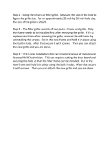
3. HOW TO INSTALL THE INDOOR UNIT .................. 13
4-Way Cassette Type
(U1 Type) ................................................................. 13
3-1. Suspending the Indoor Unit
3-2. Preparation for Suspending
3-3. Placing the Unit Inside the Ceiling
3-4. Installing the Drain Piping
3-5. Checking the Drainage
3-6. Before Installing the Ceiling Panel
3-7. Installing the Ceiling Panel
3-8. When Removing the Ceiling Panel for Servicing
3-9. Duct for Fresh Air
Wall Mounted Type (K1 Type) .................................. 21
3-10. Removing the Wall Fixture from the Unit
3-11. Selecting and Making a Hole
3-12. Installing the Rear Panel on the Wall
3-13. Removing the Grille to Install the Indoor Unit
3-14. Preparing the Indoor Side Tubing
3-15. Wiring Instructions
3-16. Wiring Instructions for Inter-Unit Connections
3-17. Shaping the Tubing
3-18. Installing the Drain Hose
Ceiling Type (T1 Type) ............................................. 26
3-19. Suspending the Indoor Unit
3-20. Duct for Fresh Air
3-21. Installing the Drain Piping
Low Silhouette Ducted Type (F1 Type) .................... 30
3-22. Required Minimum Space for Installation and
Service
3-23. Suspending the Indoor Unit
3-24. Installing the Drain Piping
3-25. Checking the Drainage
3-26. Increasing the Fan Speed
3-27. When Installing the Indoor Unit
3-28. Required Minimum Space for Installation and
Service
SUPPLEMENT ON DRAIN PIPING ........................ 36
■
■
■
■
■
4. ELECTRICAL WIRING ............................................ 37
4-1. General Precautions on Wiring
4-2. Recommended Wire Length and Wire Diameter
for Power Supply System
4-3. Wiring System Diagram
4-4. How to Connect Wiring to the Terminal
5. HOW TO INSTALL THE WIRELESS REMOTE
CONTROLLER ........................................................ 40
5-1. Wireless Remote Controller Installation
5-2. Room Temperature Sensor Setting
5-3. Address Switches
5-4. Setting the Model Code
<CZ-RWSU1U>
4-Way Cassette Type (U1 Type). . . . . . . . . . . . . . . . . .42
5-5. Indicator Section Installation
5-6. Operating Controller Installation
Ceiling Type (T1 Type). . . . . . . . . . . . . . . . . . . . . . . . . . 43
5-7. Indicator Section Installation
5-8. Operating Controller Installation
5-9. Electrical Wiring
5-10. Test Run Switch
5-11. Misoperation Alarm Indicators
<CZ-RWSC1U>
5-12. Separate Type Signal Receiving Unit Installation
5-13. Electrical Wiring
5-14. Test Run Switch
5-15. Misoperation Alarm Indicators
5-16. Basic Wiring Diagram
5-17. Wiring System Diagram for Group Control
5-18. Wiring System Diagram for Multiple Remote
Controllers
<CZ-RWSK1U>
5-19. Test Run Procedure
5-20. Check Items Before the Test Run
5-21. Preparing for the Test Run
5-22. Precautions
5-23. When Setting Indoor Unit Control PCB Switch
for Wall Mounted Indoor Unit
5-24. Diagnosis Table
6. APPENIDX .............................................................. 58
Name of Parts. . . . . . . . . . . . . . . . . . . . . . . . . . . . . . . . . 58
Care and Cleaning. . . . . . . . . . . . . . . . . . . . . . . . . . . . . 59
Troubleshooting. . . . . . . . . . . . . . . . . . . . . . . . . . . . . . . .63
Tips for Energy Saving. . . . . . . . . . . . . . . . . . . . . . . . . .63
■
■
■
■
■
■

7
1. GENERAL
This booklet briefly outlines where and how to install
the air conditioning system. Please read over the entire
set of instructions for the indoor and outdoor units and
make sure all accessory parts listed are with the system
before beginning.
1-1. Tools Required for Installation (not supplied)
1. Flathead screwdriver
2. Phillips head screwdriver
3. Knife or wire stripper
4. Tape measure
5. Level gauge
6. Sabre saw or key hole saw
7. Hacksaw
8. Core bits
9. Hammer
10. Drill
11. Tube cutter
12. Tube flaring tool
13. Torque wrench
14. Adjustable wrench
15. Reamer (for deburring)
1-2. Accessories Supplied with Outdoor Unit
See Tables 1-1 to 1-6.
1-3. Type of Copper Tube and Insulation Material
Copper tubing for connecting the outdoor unit to the
indoor unit is available in kits which contain the liquid
and gas tubing, fittings and insulation. Consult your
nearest sales outlet or A/C workshop.
If you wish to purchase these materials separately
from a local source, you will need:
1. Deoxidized annealed copper tube for refrigerant
tubing.
2. Foamed polyethylene insulation for copper tubes as
required to precise length of tubing.
Wall thickness of the insulation should be not less
than 5/16".
3. Use insulated copper wire for field wiring. Wire size
varies with the total length of wiring. Refer to
Section 4. “ELECTRICAL WIRING” for details.
CAUTION
Check local electrical codes
and regulations before
obtaining wire. Also, check
any specified instructions or
limitations.
1-4. Additional Materials Required for Installation
1. Refrigeration (armored) tape
2. Insulated staples or clamps for connecting wire
(See your local codes.)
3. Putty
4. Refrigeration tubing lubricant
5. Clamps or saddles to secure refrigerant tubing
6. Scale for weighing
Table Type
1-1 4-Way Cassette
1-2 Wall Mounted
1-3 Ceiling
1-4 Low Silhouette Ducted
1-5 Wireless Remote Controller
1-6 Timer Wired Remote Controller

8
Full-scale installation diagram
Flare insulator
Washer
Insulating tape
Hose band
Packing
Drain insulator
Drain hose
Drain hose adaptor
Sealing putty
(White)
Wire joint
Wood screw
1
2
8
1
2
1
1
2
1
1
1
1
2
Wired remote controller
(comes with 7-7/8 in. wire)
Part Name Figure Q’ty Part Name Figure Q’ty
Part Name Figure Q’ty Part Name Figure Q’ty
Full-scale diagram
Wall fixture
Rawl plug
Cover
Tapping screw
Truss-head
Phillips
4 × 5/8 in.
1
1
12
1
12
Wireless remote controller 1
1
2
2
Truss-head tapping screw
Battery
4 × 5/8 in.
Wireless remote controller
mounting cradle
1Insulator
Drain hose adaptor
1
Table 1-2 Wall Mounted
Table 1-1 4-Way Cassette
Part Name Figure Q’ty Part Name Figure Q’ty
Special washer
Drain insulator
Flare insulator
Drain hose adaptor
Drain hose clamp
Insulating tape
Vinyl clamp
Full-scale installation diagram
Sealing putty
Drain hose
T5
T3
Wire joint
Wood screw
Wired remote controller
(comes with 7-7/8 in. wire)
4
1
1
1 Set
1
6
2
1
8
1
1
1
2
2
Table 1-3 Ceiling

9
Part Name Figure Q’ty Part Name Figure Q’ty
Drain hose
Wire joint
Wood screw
Wired remote controller
(comes with 7-7/8 in. wire)
2
1
1
2
1
1
1
1
1
1
2
2
Flare insulator
Insulating tape
Jumper cable*
Hose band
Packing
Sealing putty
Drain insulator
Drain hose adaptor
Special washer
Vinyl clamp
8
8
Table1-4 Low Silhouette Ducted
<CZ-RWSK1U>
Part Name Figure Part Name Figure
Wireless remote controller 1 2
Truss-head tapping screws
Batteries
4 × 5/8 in.
‘Q’ty ‘Q’ty
Wireless remote controller
mounting cradle
Table 1-5 (Accessories for the Wireless Remote Controller)
<CZ-RWSU1U>
Part Name Figure
‘Q’ty
Part Name Figure
‘Q’ty
Operation controller 1 Spacers 2
Indicator section 1 4
Wireless remote controller 1 2
13
Batteries 2 Wire joints 4
Pan-head tapping screws
4 × 13/32 in.
Truss-head tapping screws
4 × 5/8 in.
Run Timer
Heating preparations
Vinyl clamps
L 5-29/32
Wireless remote controller
mounting cradle
12

10
Table 1-6 (Accessories for the Timer Wired Remote Controller)
Part Name Figure
‘Q’ty
Part Name Figure
‘Q’ty
Timer Wired Remote Controller
1 Spacers 2
1 Wood screws
2 Clamps
Machine screws
M4 × 1 in.
Connecting wiring
length 4 ft.
2
2
Small screws
M4 × 1-9/16 in.
Machine screws
M4 × 1 in.
Ceiling installation paper pattern
(
3-3/4 × 2-1/32 in.
)
<CZ-RWSC1U>
Part Name Figure
‘Q’ty
Part Name Figure
‘Q’ty
12
Carrier for ceiling installation 1 Wood screws 2
Wireless remote controller 1 Spacers 4
1 Wire joints 4
Batteries 2 Clamp
21
Separate type signal receiving unit
(comes with 7-7/8 in. wire)
Wireless remote controller
mounting cradle
1

11
CAUTION
1. This unit requires no additional refrig-
erant charge up to 100 ft. tubing length.
In case of more than 100 ft., additional
refrigerant charge is required.
2. In case of multi type installation, indoor
units should be installed within the
same room. If multi type indoor units
are installed in different rooms, tem-
perature control may develop problems
because thermostat operation must
follow the thermostat condition of 1
indoor unit only (the main unit).
WARNING
Always check the gas density
for the room in which the unit is
installed.
CAUTION
Pay special attention to any
location, such as a basement
or recessed area, etc. where
leaked refrigerant can collect,
since refrigerant gas is heavi-
er than air.
■ Check of limit density
When installing an air conditioner in a room, it is neces-
sary to ensure that even if the refrigerant gas acciden-
tally escapes, its density does not exceed the limit level
for that room.

12
2. SELECTING THE INSTALLATION SITE
2-1. Indoor Unit
AVOID:
areas where leakage of flammable gas may be
expected.
places where large amounts of oil mist exist.
direct sunlight.
locations near inverter lamps which may affect the
performance of the unit.
locations near heat sources which may affect the
performance of the unit.
locations where external air may enter the room
directly. This may cause “sweating” on the air dis-
charge ports, causing them to spray or drip.
locations where the remote controller will be splashed
with water or affected by dampness or humidity.
installing the remote controller behind curtains or
furniture.
locations where the receiver in the indoor unit is
exposed to the inverter lamp light. Faulty operation
of the unit occurs.
DO:
select an appropriate position from which every
corner of the room can be uniformly cooled.
select a location where the ceiling is strong enough
to support the weight of the unit.
select a location where tubing and drain pipe have
the shortest run to the outdoor unit.
allow room for operation and maintenance as well as
unrestricted air flow around the unit.
install the unit within the maximum elevation
difference above or below the outdoor unit and within
a total tubing length (L) from the outdoor unit as
detailed in the installation instructions packed with
the outdoor unit.
allow room for mounting the remote controller about
3 ft. off the floor, in an area that is not in direct
sunlight nor in the flow of cool air from the indoor
unit.
NOTE
Air delivery will be degraded if the distance from the
floor to the ceiling is greater than 10 ft.
Ceiling Type
The rear of the indoor unit can be installed flush
against the wall.
Min. 2 ft.
Air intake
Air
discharge
Min. 10 inch
Ceiling
Wall
Max 25 cm
NOTE
Min. 10 inch
Side view
Front view
Ceiling
Wall Mounted Type
Min.
6 inch
Min.
12 inch
Min.
6 inch
Low Silhouette Ducted Type
4-Way Cassette Type
10 in.
10 in.
10 in.
3 ft.
3 ft.
3 ft.
3 ft.
3 ft.
Min.8 ft.
Shows Low Silhouette Ducted Type only

13
3. HOW TO INSTALL THE INDOOR UNIT
4-Way Cassette Type
(U1 Type)
3-1. Suspending the Indoor Unit
This unit uses a drain pump. Use a level gauge to
check that the unit is level.
3-2. Preparation for Suspending
(1) Fix the suspension bolts securely in the ceiling
using the method shown in the diagrams (Figs. 3-1
and 3-2), by attaching them to the ceiling support
structure, or by any other method that ensures that
the unit will be securely and safely suspended.
(2) Follow Fig. 3-2 and Table 3-1 to make the holes in
the ceiling.
(3) Determine the pitch of the suspension bolts using
the supplied full-scale installation diagram. The
diagram and table (Fig. 3-3 and Table 3-2) show the
relationship between the positions of the suspen-
sion fitting, the unit, and the panel.
■
Type
Length
Table 3-2
Unit: inch (mm)
S-26PU1U6
(CZ-24KPU1U)
S-36PU1U6, S-42PU1U6
(CZ-36KPU1U)
A
6-3/16
(157)
6-3/16
(157)
7-5/32
(182)
7-5/32
(182)
10-9/32
(261)
11-15/32
(291)
12-1/8
(308)
13-1/16
(338)
4-7/8
(124)
4-7/8
(124)
D E B C
Hole-in-anchor
Hole-in-plug
Concrete Insert
Suspension bolt (M10 or 3/8")
(field supply)
Fig. 3-1
)gninepo gnilieC( 23/9-23
Grille center
nsion bolt pitch)epsuS( 61/31-92
X
Refrigerant
tubing side
Drain hose
side
B
(Suspension bolt pitch)
A (Ceiling opening)
Fig. 3-2
C
D
61/3
-
1
B
A
E
Suspension lug
Refrigerant tubing joint (gas tube side)
Refrigerant tubing joint
(liquid tube side)
Drain connection (other side)
(VP25)
Length
Type
Table 3-1
Unit: inch (mm)
S-26PU1U6
(CZ-24KPU1U)
S-36PU1U6, S-42PU1U6
(CZ-36KPU1U)
A
32-9/32
(820)
43-11/16
(1,110)
22-9/32
(566)
33-11/16
(856)
B
Unit: inch
Fig. 3-3
Unit: inch

14
3-3. Placing the Unit Inside the Ceiling
(1) When placing the unit inside the ceiling, determine
the pitch of the suspension bolts using the
supplied full-scale installation diagram. (Fig. 3-4)
The size of the opening for the indoor unit can be
confirmed by attaching the full-scale installation
diagram beneath the unit. (Fig. 3-4)
Tubing and wiring must be laid inside the ceiling
when suspending the unit. If the ceiling is already
constructed, lay the tubing and wiring into position
for connection to the unit before placing the unit
inside the ceiling.
(2) The length of each suspension bolt must be
appropriate for a distance between the bottom of
the bolt and the bottom of the ceiling of 5/8" or
more as shown in Fig. 3-4.
(3) Thread the 2 hexagonal nuts (field supply) and
washers onto the 4 suspension bolts as shown in
Fig. 3-5.
Use 2 sets of nuts and washers (upper and lower),
so that the unit will not fall off the suspension lugs.
(4) Remove the protective cardboard used to protect
the fan parts during transport.
(5) Adjust the distance between the unit and surface
of the ceiling. (1-7/8") (Fig. 3-4)
5/8" or more
8"/ 7 -
1
Full-scale installation diagram
(printed on a cardboard packing)
Full-scale installation
diagram
Fig. 3-4
Nuts and washers
Double nuts
(Use above and below)
Suspension bolt
Suspension lug
Upper
Lower
Notch
1-7/8"
Fig. 3-5

15
3-4. Installing the Drain Piping
(1) Prepare standard hard PVC pipe for the drain and
use the supplied drain hose and hose band to pre-
vent water leaks.
The PVC pipe must be purchased separately. The
transparent part allows you to check drainage.
(Fig. 3-6)
(2) After checking the drainage, wrap the supplied
packing and drain pipe insulator around the pipe.
(Fig. 3-7)
NOTE
Ensure the drain pipe has a downward gradient (1/100
or more) and that there are no water traps.
CAUTION
Tighten the hose clamps so
their locking nuts face upward.
(Fig. 3-6)
CAUTION
Do not install an air bleeder tube, as this may
cause water to spray from the drain tube outlet.
(Fig. 3-8)
If it is necessary to increase the height of the
drain pipe, the section directly after the connec-
tion port can be raised a maximum of 19-1/2".
Do not raise it any higher than 19-1/2", as this
could result in water leaks. (Fig. 3-9)
Do not install the pipe with an upward gradient
from the connection port. This will cause drain
water to flow backwards and leak when the unit is
stopped. (Fig. 3-10)
Do not apply force to the piping on the unit side
when connecting the drain pipe. The pipe should
not be allowed to hang unsupported from its
connection to the unit. Fasten the pipe to a wall,
frame, or other support as close to the unit as
possible. (Fig. 3-11)
Provide insulation for any drain pipe that is run
indoors.
Refer to “ SUPPLEMENT ON DRAIN PIPING”.
●
●
●
●
●
Drain hose
(supplied)
Packing
(supplied)
Transparent part for
checking drainage
Hose band
(supplied)
Drain hose
adapter
(supplied)
Hard PVC pipe
(not supplied)
Adhere with
PVC adhesive.
Fig. 3-6
Drain insulator (supplied)
Fig. 3-7
Air bleeder
Fig. 3-8
11" or less (as short as possible)
19-1/2" or less
Fig. 3-9
Upward gradient prohibited
Fig. 3-10
Support
pieces
Fig. 3-11

16
3-5. Checking the Drainage
After wiring and piping are completed, use the follow-
ing procedure to check that the water will drain smooth-
ly. For this, prepare a bucket and wiping cloth to catch
and wipe up spilled water.
(1) Take off the tube cover and through the opening,
slowly pour about 0.3 gal of water into the drain
pan to check drainage.
(2) Do Test Run to check the drainage after complet-
ing installation. When performing Test Run, refer to
the installation instructions attached to the outdoor
unit.
(3) After drain checking is finished, return the Opera-
tion Selector switch to the RUN position (ON posi-
tion ) and remount the tube cover.
WARNING
Do not supply power to the
unit until the tubing and wir-
ing to the outdoor unit are
completed.
CAUTION
Be careful since the fan will
start turning when checking
the drainage.
WARNING
To mount the tube cover,
use 5/16" (4 × 8 mm) tap-
ping screws. Do not use long
screws as they may puncture
the drain pan and cause water
leakage.
5/16"(4 × 8 mm)
tapping screw
Tube cover
Siphon
Fig. 3-12

17
Ceiling Panel
3-6. Before Installing the Ceiling Panel
(1) Remove the air-intake grille and air filter from the
ceiling panel. (Figs. 3-13 and 3-14)
(a) Remove the 2 screws on the latch of the air-
intake grille. (Fig. 3-13)
(b) Press on the 2 latches of the air-intake grille
with your thumbs in the direction of the arrow
to open the grille. (Fig. 3-13)
(c) With the air-intake grille open about 45°,
remove the safety cord (hook on the grille
side). (Fig. 3-14)
(d) Pull the air-intake grille towards you to remove
it from the ceiling panel.
(2) Pull down the two panel catches on the body of
the indoor unit body. (Fig. 3-15)
■
CAUTION
Never touch or attempt to
move the air direction louver
by hand or you may dam-
age the unit. Instead, use the
remote controller if you want
to change the direction or air
flow.
Ceiling panel
Air-intake grille
Latch
Screw
Safety cord
Air filter
45°
Fig. 3-13
Fig. 3-14
Fig. 3-15
Ceiling panel
Screws M5 with washer
Panel catch
(arrange facing downwards)
(2 locations)
(supplied)
Ceiling panel wiring
connector
Air filter
Air-intake grille
Panel catch
Unit body
Electrical
component box
Electrical
component box
Clamp

18
3-7. Installing the Ceiling Panel
(1) Lift the ceiling panel and position it to align the
panel hook with the panel catch of the indoor unit.
NOTE
The ceiling panel must be mounted in the correct
direction. Note that the 2 catches of the panel differ in
size. Confirm that the catches are correctly matched
between the ceiling panel and the indoor unit body.
(2) Next, check to see that the ceiling panel is prop-
erly aligned with the seamline of the ceiling. If it is
not, remove the ceiling panel and slightly readjust
the indoor unit body to the proper suspension
point.
(3) When the ceiling panel has been properly aligned,
use the supplied 4 mounting screws (M5) with
washers to permanently fasten the ceiling panel.
(4) Install the wiring connector from the ceiling panel
to the connector in the electrical component box of
the indoor unit. After installing the connector, use
the clamp on the body of the indoor unit to secure
the wiring.
(5) Install the air filter and air-intake grille by perform-
ing the steps in section 3-6 in reverse.
NOTE
Hook again the safety cord in its original position before
closing the air-intake grille.
3-8. When Removing the Ceiling Panel for Servicing
When removing the ceiling panel for servicing, remove
the air-intake grille and air filter, disconnect the wiring
connector inside the electrical component box, and then
remove the 4 mounting screws.

19
3-9. Duct for Fresh Air
There is a duct connection part on side of the indoor
unit. (Fig. 3-16)
(1) Accessories
Check that the following parts are in the box when
unpacking.
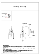
(2) Installation
Fit the duct connection box into the rectangular hole of
air-intake plenum with the accessory screws.
(M4 × L1/2", 4 pcs)
(c) Installing the indoor unit
Install the indoor unit to the ceiling.
(Install the indoor unit according to instructions enclosed
with the outdoor unit.)
Installation steps (a) to (d) are the same for both the
CZ-26BCU1U and the CZ-42BCU1U. The drawing
illustrates installation of air-intake plenum to the
CZ-26BCU1U
(a) Installing the air-intake plenum
Set the air-intake plenum to the indoor unit taking care
not to set to the incorrect direction.
(b) Installing the duct connection box
Fasten the duct connection flange to the duct connection
box with the accessory screws. (M4 × L1/2", 4 pcs)
Fasten the air-intake plenum with the supplied screws.
(M5 × L4-7/8", 4 pcs)
CAUTION
When installing in a pre-
existing location, install the
indoor unit before installing
the duct connection box.
Air-intake plenum Type
CZ-26BCU1U
CZ-24KPU1U
(S-26PU1U6)
CZ-42BCU1U
CZ-36KPU1U
(S-36PU1U6, S-42PU1U6)
Air-intake plenum (for fastening)
Duct connection flange/box (for fastening)
For fresh air intake
2-5/32
2-3/8
4-ø1/8 hole
ø4-13/32
Detail of fresh air intake
2P socket (Green)
3P socket (White)
2P socket (Green)
3P socket (White)
(ceiling panel side)
Panel lead wire (3P, 2P)
(switch box side)
Fig. 3-16
Fig. 3-17
Unit: inch
Air-intake plenum (including Duct connection box and
flange) are attached to the indoor unit when used to
take fresh outdoor air.
NAME
Q’ ty
4
REMARKS
8
1
(for fresh air)Duct connection box
(for connecting fresh air duct)
1
Duct connection flange
Screw (M5xL4-7/8”)
Screw (M4xL4-1/2”)
the air-intake plenum and fasten it to the side of the
Clamper
Air-intake
plenum
(M5 × L4-7/8", 4 pcs)
Installation screws
Socket
cover
Indoor
unit

20
(d) Installing the ceiling panel
Attach the ceiling panel to the air-intake plenum.
Drawing the panel downwards sets the panel in position
temporarily with the panel catch (at 2 locations).
Remove the socket cover of the air-intake plenum and pass
the 8P sockets through it.
(Fix the panel lead wire to air-intake plenum side clamper.)
Connect the 3P socket (white) and 2P socket (green) to the
other side of the 3P socket (white) and 2P socket (green)
respectively.
Reattach the socket cover.
Fig. 3-18
Duct connection box
Duct connection flange
Panel catch
(M4xL1/2”, 4pcs.)
Installation screws
Ceiling panel
Please fix the socket cover located on the switch box
after closing the lid for the switch box.
CAUTION
Take adequate precautions
when installing onto the
ceiling.
The air-intake plenum is
especially prone to rupture
if struck on it's side.
/