Reznor RCB User manual

Category
Thermostats
Type
User manual

This manual is also suitable for

Form CP-MAPSIII-D21, Doc No 303070, Page 1
Form CP-MAPSIII-D21 (09-15)
Applies to: Models RCB, RDB, RECB, REDB, RDCB, RDDB
Module Air Processing Systems (MAPS III) Manual for Option D21 Makeup Air Control
Example of Remote Controller Display (Option RB5 or RB6) Key Symbols
Function Key Identication
Alarm Prg Esc Up Enter Down
Function Key Display on the
Remote Controller
1.1 Display Function
Keys
The control system utilizes a factory installed remote display which allows for complete access to unit test features, schedules,
discharge air setpoints, fan control, alarms, and other unit operational setpoints. The control features include:
• Local and remote alarming
• Integrated time clock
• Compressor anti-cycle protection and minimum “on/off”
cycle rates
• Multiple protocol support [BACnet
®
(MSTP) or LonWorks
®
]
• Alarm shutdown feature
• Commissioning and test mode functions
• Optional wall mounted or handheld remote display
• Energy conscious applications
• TAB menu for creating a backup of setpoints
1.0 Digital
Controller
1.0 Digital Controller ............................................1
1.1 Display Function Keys ...................................1
1.2 Thermostat Display ....................................... 2
1.3 Controller hardware input – output points .....4
2.0 Sequence of Operation .................................5
2.1 States of Operation .......................................5
2.2 Modes of Operation .......................................6
3.0 Controls .......................................................... 6
3.1 Supply Fan Control........................................6
3.2 Intake Damper Control ..................................8
3.3 Temperature And Humidity Control ...............9
3.4 Heating Control ...........................................10
3.5 Cooling Control............................................10
3.6Dehumidication ......................................... 11
3.7SpaceTemperatureControlandSetpointDenitions
12
4.0 Safeties and Alarms .................................... 13
4.1 Alarms .........................................................13
4.2 Alarm Management .....................................16
5.0 Start Up .........................................................19
5.1 Set the Date, Time on the controller Clock & unit time
schedule ...................................................... 19
5.2 Setting the Unit for Operation via the Digital Input
Closure or Time Schedule - Option D21......20
5.3 Unit Test Mode ............................................20
6.0 Controller History Log .................................24
7.0 Controller Display Menus ...........................25
8.0 Communication Cards ................................34
8.1 BACnet
®
MSTP (Option BHB8) Communication
34
8.2 LonWorks
®
(Option BHB7) Communication 38
Index ...................................................................42
Table of Contents
Form CP-MAPSIII-D21, Doc No 303070, Page 2
Mode Button:
When pressed
will allow a
State Selection
of Heat, Cool or
Auto
Fan Button:
When pressed
will initiate
the temporary
occupied period.
On / Off Button:
When pressed while
the unit is in the
Heat, Cool, or Auto
State, will set the
unit State to OFF.
When Pressed while
the unit is in the Off
State, will set the
Unit State to the
previous Heat, Cool
or Auto State.
Set Point Adjustment Dial:
For temperature adjustments, press inward on the
dial once and turn the dial clockwise to increase
and counterclockwise to decrease the desired
temperature setpoint. For humidity setpoint
adjustments, press the dial inward twice and turn
the dial clockwise to increase and counterclockwise
to decrease the desired humidity setpoint.
User Space Mounted
Thermostat, Option CL78
The user display shall show space temperature, space humid-
ity, unit status, and time in its normal state.
1.0 Digital Controller (cont’d)
1.2 Thermostat Display
Optional Space Temperature and Humidity Averaging Feature:
Up to 5 space sensors may be added to the control system in addition to the CL78 for a total of 6 space inputs.
These devices are combination temperature and humidity sensors and operate on a RS-485 communication trunk.
Space Averaging
Sensor
Addressable Dip
Switch Settings:
User must set
the addresses
accordingly in the
eld.
Note: Refer to the Installation
manual and or unit wiring
drawingsforspecicwiring
information.
Form CP-MAPSIII-D21, Doc No 303070, Page 3
1 2
3 4 5 6 7 8
ON
1 2
3 4 5 6 7 8
ON
RETURN AIR DIP SWITCH
POSITIONS 1 & 7 “ON”
EXHAUST DIP SWITCH
POSITION 7 “ON”
ADDRESS 128
RETURN AIR TEMP & HUMIDITY
SENSOR
ADDRESS 129
EXHAUST AIR TEMP & HUMIDITY
SENSOR
Exhaust Air / Return Air
Temp & Humidity Sensor
Addressable Dip Switch
Settings: Factory set when
ordered on new production
units.Forretrotstheuser
must set the addresses
accordinglyintheeld.
Optional Exhaust Air / Return Air Temp & Humidity Sensors:
These sensors are duct mount style and operate on a RS-485 communication trunk.
Note: Refer to the Installation
manual and or unit wiring
drawingsforspecicwiring
information.
Form CP-MAPSIII-D21, Doc No 303070, Page 4
1.3 Controller hardware input – output points
Input
Terminal
Input Point
Name
Input Description Signal type Signal Range
Always
Active
J23
FB2
Spc_Temp Space Temp - up to a total of 6 inputs
RS-485
Communication
Spc_Humidity Space Humidity - up to a total of 6 inputs
U1 OA_Hum_Raw Outside Air Humidity 0 -10 Vdc 0 to 100% RH x
U2 OA_Temp_Raw Outside Air Temp Thermistor 10K-2 -35 °F to 240 °F (-37°C to 115°C) x
U3 Ext_Dmpr_Cmd External Unit Damper Command 0 -10 Vdc 0 to 100%
U4 DA_Temp Discharge Air Temp Thermistor 10K-2 -35 °F to 240 °F (-37°C to 115°C) x
U5 CC_Temp Cooling Coil Discharge Air Temp Thermistor 10K-2 -35 °F to 240 °F (-37°C to 115°C) x
U6 MA_Temp Mixed Air Temp Thermistor 10K-2 -35 °F to 240 °F (-37°C to 115°C) x
U7 Bldg_Pressure Building Static Pressure 0 - 10 Vdc -0.5” iwc thru + 0.5”iwc
U8 Duct_Pressure Duct Static Pressure 0 - 10 Vdc 0 - 2.5” iwc
U9 Spc_CO2 Space CO
2
0 - 10 Vdc 0 - 2,000 ppm
J26
FB2
RA_Temp Return Air Temp
RS-485
Communication
RA_Humidity Return Air Humidity
J26
FB2
EA_Temp Exhaust Air Temp
RS-485
Communication
EA_Humidity Exhaust Air Humidity
ID1 SF_Sts Supply Fan Status Dry Contact Open = “OFF” / Close = “ON” x
ID2 Filter_Sts Main or ERV Dirty Filter Status Dry Contact Open = “OFF” / Close = “ON”
ID3 Safety_Sts Safety Input Status Dry Contact Open = “ALARM” / Close = “NORMAL” x
ID4 Ext_OCC Occupied Mode Input Dry Contact Open = “OFF” / Close = “ON”
ID9 Ext_ Switch_1 External Damper Position Sw 1 Dry Contact Open = “OFF” / Close = “ON”
ID10 Ext_ Switch_2 External Damper Position Sw 2 Dry Contact Open = “OFF” / Close = “ON”
ID14 Phase_Alarm Phase Protection Alarm Dry Contact Open = “OFF” / Close = “ON”
ID15 Htr_1_Sts Gas Heater 1 Status
Rib Relay N.O.
Contact
Open = “OFF” / Close = “ON”
ID16 Htr_2_Sts Gas Heater 2 Status
Rib Relay N.O.
Contact
Open = “OFF” / Close = “ON”
Output
Terminal
Output Point Name Output Description Signal / Range Signal Range
Always
Enabled
Y1 Damper_Cmd Damper Output Command 0 – 10Vdc 0 – 100% Open x
Y2 SF_VFD_Cmd Supply Fan VFD Command 0 – 10Vdc 0 – 100% Flow
Y3 HX1_Mod_Cmd
Gas Heating 1 Modulation Command 2 – 10Vdc 0 – 100% Capacity
Electric Heating Modulation Command 0 – 10Vdc 0 – 100% Capacity
Y4 HX2_Mod_Cmd Gas Heating 2 Modulation Command 2 – 10Vdc 0 – 100% Capacity
Y5 RH_Mod_Cmd Reheat Modulation Command 0 – 10Vdc 0 – 100% Capacity
NO1 SF_Cmd Supply Fan Command 24Vac Contact Open = “OFF” / Close = “ON” x
NO2 Comp_Stg1_Cmd Compressor Stage 1 Command 24Vac Contact Open = “OFF” / Close = “ON” x
NO3 Comp_Stg2_Cmd Compressor Stage 2 Command 24Vac Contact Open = “OFF” / Close = “ON”
NO4 Comp_Stg3_Cmd Compressor Stage 3 Command 24Vac Contact Open = “OFF” / Close = “ON”
NO5 Comp_Stg4_Cmd Compressor Stage 4 Command 24Vac Contact Open = “OFF” / Close = “ON”
NO7 Alm_Rly_Cmd Unit General Alarm Relay Command 24Vac Contact Open = “OFF” / Close = “ON” x
NO8 HX_Stg1_Cmd Heating Stage 1 Command 24Vac Contact Open = “OFF” / Close = “ON”
NO9 HX_Stg2_Cmd Heating Stage 2 Command 24Vac Contact Open = “OFF” / Close = “ON”
NO10 HX_Stg3_Cmd Heating Stage 3 Command 24Vac Contact Open = “OFF” / Close = “ON”
NO11 HX_Stg4_Cmd Heating Stage 4 Command 24Vac Contact Open = “OFF” / Close = “ON”
NO12 HX_Stg5_Cmd Heating Stage 5 Command 24Vac Contact Open = “OFF” / Close = “ON
NO13 HX_Stg6_Cmd Heating Stage 6 Command 24Vac Contact Open = “OFF” / Close = “ON”
NO17 RH_Cmd Reheat compressor Command 24Vac Contact Open = “OFF” / Close = “ON”
Form CP-MAPSIII-D21, Doc No 303070, Page 5
The makeup air control system operates the supply fan, the intake dampers, DX
cooling, and gas or electric heat to maintain a set of discharge air temperature control
setpoints.
The unit discharge air temperatures fall within the following three categories:
1. Unit supplies neutral temperature air that does not affect space
conditions.
2. Unit supplies cold temperature air to provide space cooling.
3. Unit supplies hot temperature air to provide space heating.
NOTE: Heating applies only when a unit is ordered with a gas or electric
heat section. Heating is included in all control instructions.
Thesequenceisbrokenintoveprimarystatesofoperation.
2.0 Sequence of
Operation
2.1 States of
Operation
The unit can switch between states based on the following:
• Controller Display
• th-tune Space Control Device (Option CL78)
• Building Automation Command (Option BHB7 or BHB8)
• Automatically based upon sequence of operation.
The unit state is the primary determination of individual component function.
1. Off
The unit supply fan and all associated mechanical
equipment is OFF in this state. There are no
associated sequences of operation in this state. The
unit will only switch to the OFF state when the state is
manually selected through the th-tune device (Option
CL78), unit display, or building automation network
communication point. Upon initial power, Unit OFF is
the default state.
2. Off / Alarm
The Off / Alarm state can only occur from a sequence
“failure”. The unit will switch to this state from the
heating, cooling, or auto state. The unit will stop all
mechanical operation until the “failure” condition(s)
are resolved. The unit will be OFF. Upon resolving the
failure, the unit will return to heating, cooling, or auto
state. Alarms can also be cleared by resetting power to
the unit.
3. Heat (optional)
From the th-tune device (Option CL78), controller
display, or BMS, the heat state can be selected. The
supply fan will run and the mechanical heating and
the dampers will be operated to maintain heating
sequence of operation. The unit will not automatically
switch to other states except Off / Alarm.
4. Auto
From the th-tune device (Option CL78), controller
display, or BMS, the auto state can be selected. Upon
initial selection of the auto state, the unit will be in the
auto-heating state (if equipped) whenever the outdoor
air temperature is below 65°F(18°C), otherwise the
unit will be in the auto-cooling state. The unit will
change to auto cooling/auto-heating state whenever
the temperature crosses the changeover setpoint
for more than 15 minutes or is more than 5°F(2.8°C)
beyond the changeover setpoint.
The unit mechanical function is exactly the same
in either cooling or heating state, other than the
sequence’s ability to change states. NOTE: The unit
switches between heating and cooling based upon
outside air temperature. Space temperature does not
dictate heating or cooling mode.
5. Cool
From the th-tune device (Option CL78), controller
display, or BMS, the cool state can be selected. The
unit supply fan will run and the mechanical cooling and
the dampers will be operated to maintain the cooling
sequence of operation. The unit will not automatically
switch to other states except Off / Alarm.
Form CP-MAPSIII-D21, Doc No 303070, Page 6
Occupied & Unoccupied
When the unit is called to operate in the auto, heating, or cooling state(s), the unit will
function in one of two modes: occupied or unoccupied. The unit will run in occupied
or unoccupied mode based upon one of the following three user selected commands:
1. Internal Time Clock Schedule Selects Occupied or Unoccupied Mode.
2. Physical input point (ID4) (Contact closed = Occupied)
3. Building Automation network variable (LonWorks
®
or BACnet
®
)
From the display, the user will select the mode control type. All other input methods
are ignored.
Heating Sequence
1. Supply Fan = ON
2. Dampers = Mod
3. Heat = ON/Mod
Discharge Air
Temperature Setpoint
1. Neutral Air =
70°F (21°C)
2. Space Heat =
90°F (32°C)
Manual Heating
State
Mode
Occ or Unocc
Unit OFF
Requires
Reset
Manual Cooling
State
Unit Test
Mode
No Control
All Mechanical
Equipment = OFF
All Outputs OFF
or Zero State
1. Supply Fan(s) =
Intermittent when
th-Tune Device is
enabled.
See Note 1.
2. Dampers = Closed
See Note 2.
Discharge Air
Temperature Setpoint
1. Space Heat =
90°F (32°C)
Cooling Sequence
1. Supply Fan = ON
2. Dampers = Mod
3. Cooling = ON/Mod
4. Dehum = Allowed
Discharge Air
Temperature Setpoint
1. Neutral Air =
70°F (21°C)
2. Space Cool =
55°F (12°C)
Mode
Occ or Unocc
1. Supply Fan(s) =
Intermittent when
th-Tune Device is
enabled. See Note 1.
See Note 2.
2. Dampers = Closed
3. Dehumid = Allowed
1. Space Cool =
55°F (12°C)
Auto Heat / Cool
State
Outside Air
Temp >65°F
(18°C)
Control System Unit State, Mode, Major DAT Septoint
Off / Alarm
State
Unit OFF
State
Heating Sequence
Cooling Sequence
Discharge Air
Temperature Setpoint
No Yes
State
Mode
Function
Unocc ModeOcc Mode
Unocc Mode
Occ Mode
NOTE 1. Intermittent operation of the
supply fan will be based on an
increased space cooling setpoint and
a decreased space heating setpoint
during the unoccupied mode.
NOTE 2. For damper control options
GF1 & GF2 damper operation will be
permitted when the unoccupied
ventilation variable is set to on.
User has
pseudo
manual
control of all
mechanical
operation
Tab:Function
Set Fan
Speeds
2.0 Sequence of Operation (Cont’d)
3.1 Supply Fan
Control
The supply fan provides the total volume of conditioned air to the space at a given rate.
The rate is controlled by unit state, mode, and the selection of one of the six sequences
of operation.
1. High Low Volume Control (Option VFC1)
2. Duct Static Pressure (Option VFC3)
3. Building Static Pressure (Option VFC4)
4. Summer/Winter Constant Volume (Option VFC9)
3.0 Controls
2.2 Modes of
Operation
Form CP-MAPSIII-D21, Doc No 303070, Page 7
Manual Heating
State
Mode
Occ or Unocc
Unit OFF
State
Control System Unit State, Mode, Major DAT Septoint
Manual Cooling
State
Off / Alarm
State
Unit Test
Mode
Fan = OFF
Mode
Occ or Unocc
Auto Heat / Cool
State
Outside Air
Temp >65°F
(18°C)
Fan = OFF
Fan = Intermittent
See Note 1.
Fan = ON and
Speed = to Maximum
Speed Setpoint
Fan = ON
Fan = ON
Occ Mode
Unocc Mode
Unocc Mode
Occ Mode
Fan = Intermittent
See Note 1.
No Yes
State
Mode
Fan
Function
NOTE 1. - Intermittent operation of the supply fan will be based on an increased space cooling setpoint and
a decreased space heating setpoint during the unoccupied mode.
Supply Fan Control:
Occupied Mode
When the unit is called to be in occupied mode, the supply fan will start. If the unit is
conguredwitha100%outsideairdamper,thedamperactuatoriselectricallyinter-
locked such that the supply fan cannot start until the damper is 80% open.
When the Supply fan is commanded OFF, any active heating or cooling operations will
be shut down and the supply fan will stop after an adjustable time delay.
The rate is controlled by unit state, mode and the selection of one of the following
sequences of operation:
1. High - Low Fan Speed Control (VFC1) The variable frequency drive is
commanded ON from NO1. There are two fan speed states - active heating/
cooling and fan only. When the fan is ON and the system is in either the space
heating or space cooling mode, the unit will operate on high fan speed. When
the fan is ON and the system is not in either the space cooling or space heating
mode, the supply fan will operate on low fan speed.
2. Duct Static Pressure Control (0.0” to 2.5” iwc) (Option VFC3) The variable
frequency drive is commanded ON from NO1. The fan modulates between the
user adjustable minimum and maximum fan speed setpoints using a PI loop to
maintain the duct static pressure setpoint, +0.5”iwc default.
3. Building Static Pressure Control (-0.5” to 0.5” iwc) (Option VFC4) The
variable frequency drive is commanded ON from NO1. The fan modulates
between the user adjustable minimum and maximum fan speed setpoints using a
PI loop to maintain the building static pressure setpoint, +0.1”iwc default.
4. Summer/Winter Constant Volume (Option VFC9) The variable frequency drive
is commanded ON from NO1. The unit ramps up to a user set supply fan speed
setting. There are two individual supply fan speed % setpoints, one for heating
and one for cooling. When the Unit is in Space or Neutral air Heating, the supply
fan will use the heating speed % setpoint. When the unit is in any other mode,
the supply fan will use cooling speed % setpoint.
A 30-second acceleration and deceleration rate for the supply fan to ramp between
the minimum and maximum motor frequency is factory set via the unit variable
frequency drive.
Supply Fan Control : Unoccupied Mode
Whenconguredforspacecontrol,thesupplyfanoperationwillbeintermittentbased
on the zone temperature. See Temperature and Humidity Control section, Paragraph
3.7,forspacecontrolandsetpointdenitions.
Form CP-MAPSIII-D21, Doc No 303070, Page 8
3.2 Intake Damper
Control
The intake dampers operate based upon state, mode and one of the following user
selected sequences. The dampers are normally open and operational in the occupied
mode and closed to outside air in the unoccupied mode depending on the user selec-
tion.
1. 100% OA, (Option GF2A)
When the unit is to start, the outside air damper will modulate (point Y1 = 10Vdc)
and the supply fan will be commanded ON (point NO1 = On). If the unit is equipped
with an outside air damper, the damper actuator is electrically interlocked to the fan
start/stop such that the supply fan cannot start until the damper is 80% open. Air
inletcongurationOptionsAR8,AR2D,AR2L,andAR2Yareelectricallyinterlocked
with the supply fan.
OFF and Alarm Modes - The damper will be closed. Y1 = 0%.
2. External 0-10vdc Input, (Option GF1)
Occupied & Unoccupied Mode
The dampers will modulate from 0-100% (point Y1 = 0 to 10 Vdc) based user
supplied 0 - 10 Vdc input. 0 Volts input is 0% damper while 10V input is 100%
damper position. This is not allowed with Options AR8, AR2D, AR2L & AR2Y. The
software does not prevent the selection of this option. The fan status switch will
handletheblockowcondition.ThedamperisNOTelectricallyinterlockedwith
the supply fan.
Unoccupied OFF and Alarm Modes
The damper will be closed (Y1 = 0%).
NOTE: For unoccupied operation of this damper control option, set the unoccupied
ventilation enable variable to ON.
3. Two-Position Dampers (Option GF2)
Occupied Mode
The damper will open to the user adjustable occupied damper position setpoint
value (point Y1=10Vdc). For the damper options with only 100% outside air, the
mechanical interlock of 80% will not allow the fan to start. Adjust the outside air
setpoint to reach the minimum electrical interlock position.
Unoccupied Mode
With the unoccupied ventilation enable variable set to ON, the damper will open to
the user adjustable unoccupied damper position setpoint value (point Y1=0Vdc).
For the damper options with only 100% outside air, the mechanical interlock of
80% will not allow the fan to start. Adjust the outside air setpoint to reach the
minimum electrical interlock position. With the unoccupied ventilation enable
variable set to OFF, the damper will be commanded to 0%.
OFF and Alarm Modes - The damper will be closed. Y1 = 0%.
4. Four Positions based on 2 Digital Inputs (Option GF4)
Occupied Mode
Thedamperwillopentotheuseradjustabledenedpositionbasedupontwo
hardware input switches (ID9 & ID10).
Variable Name
Input Switch
Default Damper
Position
Display
Range
Y1 Output
Range
ID9 ID10
Aux_1_SP Open Open 20% 0-100% 0 – 10V
Aux_2_SP Close Open 40% 0-100% 0 – 10V
Aux_3_SP Open Close 60% 0-100% 0 – 10V
Aux_4_SP Close Close 80% 0-100% 0 – 10V
This option is not allowed with AR8, AR2D, AR2L, and AR2Y. The software does
not prevent the selection of this option. The fan status switch will handle the block
owcondition.
Unoccupied, OFF and Alarm Modes -The damper will be closed ( Y1 = 0%).
5. Building Pressure Control (Range -0.5 to 0.5” iwc) (Option GF5)
Occupied Mode
The dampers will modulate using a PI loop to maintain the building static pressure
setpoint, default 0.1” iwc Y1 will modulate from 0-100% open, 0-10V.
Unoccupied, OFF and Alarm Modes - The damper will be closed (Y1 = 0%).
3.0 Controls (Cont’d)
Form CP-MAPSIII-D21, Doc No 303070, Page 9
The unit is inherently a discharge air temperature control system. The unit will
operate to maintain one of the following discharge air setpoints depending on the
state and mode. Selected setpoints are user adjustable from the unit display and the
wall mounted user interface.
Discharge Air Temperature (DAT) Setpoint Decision Tree
Space Temperature Control Req’d
Initiate: Space Temp 4°F(2.1°C) > SpcEffClgSP
Release: Space Temp 1°F(.4°C) < SpcEffClgSP
DAT Setpoint = 55°F(12°C); 50-100°F(10-37°C)
Space Humidity Control Req’d
Initiate: Space %RH 10% >
Setpoint
Release: Space %RH 5% < Setpoint
Space %RH Setpoint = 55%; 35-75%
DAT Sp = 70°F(21°C); 50-100°F(10-37°C)
Main Coil Setpoint CC-T = 52°F(11°C)
Required
State
•Heat
•Cool
•Auto
(Unit cycles ON based on Space Temperature
Control.)
DAT Setpoint = 90°F(32°C); 50-100°F(10-37°C)
Space
Heating
Required
HEATING
Space
Cooling
Required
Neutral Air Temperature Control
DAT Sp = 70°F(21°C); 50-100°F(10-37°C)
COOLING
Space Temperature Control Req’d
Initiate: Space Temp 4°F(2.1°C) > SpcEffClgSP
Release: Space Temp 1°F(.4°C) < SpcEffClgSP
DAT Setpoint = 55°F(12°C); 50-100°F
(10-37°C)
(Unit Cycles ON based on
Space Temperature Control.)
Occ
Mode
Unocc
Mode
Space
Dehumidification
Required
Occ
Mode
Unocc
Mode
Space
Cooling
Required
Initiate: Space Temp 5°F(2.8°C) > SpcHtgSP
Release: Space Temp 1°F(.4°C) < SpcHtgSP
DAT Setpoint = 55°F(12°C); 50-100°F (10-37°C)
(Auto Heating Only)
Occ
Mode
Unocc
Mode
Occ
Mode
Unocc
Mode
YES
YES
YES
YES
Unit Off
NO
NO
Occ
Mode
Unocc
Mode
Neutral Air Dehumidification Control
Req’d Dehum OAT Dewpoint > 58°F(14°C);
48-90°F(8-32°C)
DAT Setpoint = 70°F(21°C);
50-100°F(10-37°C)
Main Coil Setpoint CC-T = 52°F(11°C)
Neutral Air Temperature Control
Neutral Air
Dehum
Req’d
NO
Unit Off
YES
NO
NO
* If the space temperature sensor (th-Tune) is not enabled or fails,
the logic will ignore the space requirements and operate to maintain
neutral air temperature and neutral air dehumidification control. If the
th-Tune is enabled and fails, an alarm condition is created.
Occ
Mode
Unocc
Mode
Space Humidity Control Req’d
Initiate: Space %RH 10% > Setpoint
Release: Space %RH 5% < Setpoint
Space %RH Setpoint = 55%; 35-75%
DAT Sp = 70°F(21°C); 50-100°F(10-37°C)
(Unit cycles on based upon Space
Dehumidification Control.)
Main Coil Setpoint CC-T = 52°F(11°C)
DAT Setpoint = 70°F(21°C);
50-100°F(10-37°C)
Space Temperature Control Req’d
Initiate: Space Temp 4°F(2.1°C) > SpcEffHtgSP
Release: Space Temp 1°F(.4°C) < SpcEffHtgSP
DAT Setpoint = 90°F(32°C); 50-100°F(10-37°C)
Space Temperature Control Req’d
Initiate: Space Temp 4°F(2.1°C) > SpcEffHtgSP
Release: Space Temp 1°F(.4°C) < SpcEffHtgSP
Space Temperature Control Req’d
Or Sliding Scale
Unit Off
Reset Schedule
Outside Air
Temperature
Discharge Air
Temperature
30°F
(-1.1°C)
75°F
(23.8°C)
65°F
(18.3°C)
65°F
(18.3°C)
Sliding Scale: Temperature Reset Schedule Setpoint (heating Only)
The user can also select a reset schedule for the discharge setpoint used when in
neutral air heating mode.
3.3 Temperature
And Humidity
Control
Form CP-MAPSIII-D21, Doc No 303070, Page 10
3.0 Controls
(Cont’d)
3.4 Heating Control
3.4.1 Electric Heat Staging
A call for heat will occur when the discharge air temperature is 5°F(2.8°C) below
the active setpoint. When the OAT is below 65°F/18°C (Heating Lockout SP), the
unit enables the electric heat to maintain the active setpoint. The unit will stage as
shown in the staging chart and the PI loop will activate. Stages should be assumed
cumulative from the previous stage.
Electric Heat Staging
PI Loop Control: All Statements Must Be True To Activate or De-Activate.
All stages will have an adjustable min ON and OFF time.
Stage Outputs
Increase
Inter-Stg
Timer
Activate
Decrease
Inter-Stg
Timer
De-activate
Stg 1 NO8 = ON
DAT 5°F (2.8°C) below setpoint
(Y3 Modulates via Heating Demand)
15 min
Heating Demand < 2.5% & DAT 5°F
(2.8°C) above setpoint
Stg 2 NO9 = ON 10 min
Heating Demand > 70% & DAT
5°F(2.8°C) below setpoint
2 min
Heating Demand < 5% & DAT
5°F(2.8°C) above setpoint
Stg 3 NO10 = ON 10 min
Heating Demand > 75% & DAT
5°F(2.8°C) below setpoint
2 min
Heating Demand < 10% & DAT
5°F(2.8°C) above setpoint
Stg 4 NO11 = ON 10 min
Heating Demand > 80% & DAT
5°F(2.8°C) below setpoint
2 min
Heating Demand < 20% & DAT
5°F(2.8°C) above setpoint
Stg 5 NO12 = ON 10 min
Heating Demand > 85% & DAT
5°F(2.8°C) below setpoint
2 min
Heating Demand < 30% & DAT
5°F(2.8°C) above setpoint
Stg 6 NO13 = ON 10 min
Heating Demand > 90% & DAT
5°F(2.8°C) below setpoint
2 min
Heating Demand < 40% & DAT
5°F(2.8°C) above setpoint
All parameters are factory level access.
3.4.2 Gas Heat Staging
A call for heat will occur when the discharge air temperature is 5°F(2.8°C) below
the active setpoint. When the OAT is below 65°F/18°C (Heating Lockout SP), the
unit enables the gas heat to maintain the active setpoint. The unit will stage and
modulate as shown in the staging chart and the PI loop will activate. Stages should
be assumed cumulative from the previous stage.
Gas Heat Staging
PI Loop Control: All Statements Must Be True To Activate or De-Activate.
All stages will have an adjustable min ON and OFF time.
Stage Outputs
Increase
Inter-Stg
Timer
Activate
Decrease
Inter-Stg
Timer
De-activate
Stg 1
Y3 = 24% for
30 seconds
& NO8 = ON
DAT 5°F (2.8°C) below setpoint
(Y3 Modulates Heat Exchanger 1
via Heating Demand)
15 min
Heating Demand < 2.5% & DAT
5°F (2.8°C) above setpoint
Stg 2
Y4 = 24% for
30 seconds
NO9 = ON
10 min
Heating Demand > 50% (Y3
Heat Exhanger 1 = 100%) & DAT
5°F(2.8°C) below setpoint (Y4
Modulates Heat Exchanger 2 via
Heating Demand)
15 min
Heating Demand < 25% & DAT
5°F(2.8°C) above setpoint
All parameters are factory level access.
When the unit has a call for cooling from the th-tune device (Option CL78) in the
space, it will use the unit U4 DAT input and the cooling demand to achieve the space
cooling discharge air temperature setpoint. A call for space cooling takes priority over
acallforspacedehumidication.
A call for mechanical cooling will occur when the discharge air temperature is
5°F(2.8°C) above the active setpoint. When the OAT is above 65°F/18°C (Cooling
Lockout SP), the unit enables the mechanical cooling to maintain the active setpoint.
Cooling capacity/staging will follow a PI loop to maintain the active setpoint. Space
CoolingActive=SpacedehumidicationY5Reheat_Mod_CapacityandNO17Reheat
Compressor Command not permitted.
3.5.1 Cooling Staging
Control Y3 (with the
Option CL78 th-tune
device ENABLED and
COMMUNICATING)
3.5 Cooling Control
Heat Exchanger 1 Heat Exchanger 2
0%
100%
Output Y3
Heating Demand
100%
10 Vdc
Output Y4
0%
2 Vdc
100%
10 Vdc
0%
2 Vdc
50%
Form CP-MAPSIII-D21, Doc No 303070, Page 11
Space Cooling Inactive = Space dehumidication Y5 Reheat_Mod_Capacity and
NO17 Reheat Compressor Command permitted. If the Space Cooling is inactive and
thespacehumidityisabovethespacedehumidicationsetpoint,theunitwillenterthe
space dehumidication mode. While in the space dehumidication mode, the main
cooling compressors will be enabled to maintain a 52°F(11°C) cooling coil discharge
setpoint and will use the U5 CC_Temp sensor.
See dehumidication commands section for details on the operation of the reheat
compressorandmodulatingvalveY5outputinspacedehumidicationmode.
The unit will use the U4 DAT input and cooling demand to achieve the neutral discharge
air temperature setpoint.
A call for mechanical cooling will occur when the discharge air temperature is 5°F(2.8°C)
above the neutral air setpoint. When the OAT is above 65°F/18°C (Cooling Lockout
SP), the unit enables the mechanical cooling to maintain the neutral air setpoint. Cool-
ing capacity/staging will follow a PI loop to maintain the active setpoint.
When the OA dewpoint is greater than 58°F(14°C) the unit will enter the neutral air
dehumidicationmode.Whileintheneutralairdehumidicationmode,themaincool-
ing compressors will be enabled to maintain a 52
°F(11°C) cooling coil discharge set-
pointandwillusetheU5CC_Tempsensor.Seedehumidicationcommandssection
for details on the operation of the reheat compressor and modulating valve Y5 output
inneutralairdehumidicationmode.
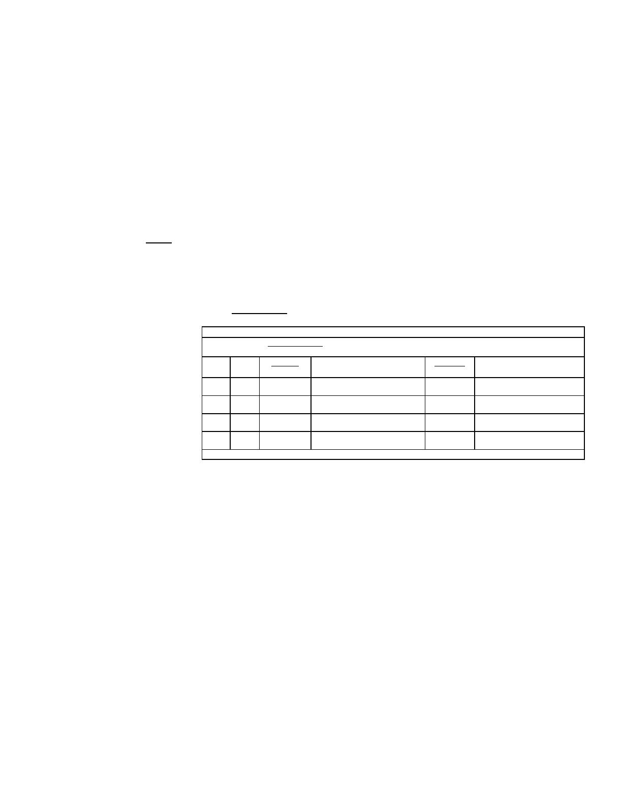
3.7.1 Occupied Space Temperature Control and Setpoint
DX Mechanical Cooling Staging
PI Loop Control: All Statements Must Be True To Activate or De-Activate
All stages will have an adjustable min ON and OFF time
Stage Output
Increase
Stage Timing
Activate
Decrease
Stage Timing
De-activate
Stg 1 NO2 5 min DAT 5°F(2.8°C) above setpoint 5 min
Cooling Demand < 10 % & DAT
5°F(2.8°C) below setpoint
Stg 2 NO3 5 min
Cooling Demand > 70% & DAT
5°F(2.8°C) above setpoint
5 min
Cooling Demand < 50% & DAT
5°F(2.8°C) below setpoint
Stg 3 NO4 5 min
Cooling Demand > 80% & DAT
5°F(2.8°C) above setpoint
5 min
Cooling Demand < 55% & DAT
5°F(2.8°C) below setpoint
Stg 4 NO5 5 min
Cooling Demand > 90% & DAT
5°F(2.8°C) above setpoint
5 min
Cooling Demand < 60% & DAT
5°F(2.8°C) below setpoint
All parameters are factory level access.
3.6 Dehumidication
Dehumidication Commands
Wheneitherthespacedehumidicationmodeortheneutralairdehumidicationmode
are active, the main evaporator compressor(s) will be enabled to maintain a 52°F(11°C)
cooling coil discharge setpoint and will use the U5 CC_Temp sensor. The reheat com-
pressor and the reheat valve output Y5 will be enabled to modulate to maintain the
reheat setpoint 70°F(21°C) via the U4 DAT temp sensor.
Any of the following conditions will lockout the space dehumidication Mode:
1. The outdoor air temperature is below the reheat lockout setpoint, (58°F/14°C,
reheat lockout, range 50-100°F/10-37°C) Drybulb.
2. The outdoor air temperature is above the reheat high lockout setpoint.
(100°F/37°C, reheat high lockout, range 50-120°F/10-48°C) Drybulb
3. The space cooling mode is active.
4. Cooling Coil Sensor failure.
Any of the following conditions will lockout the neutral air dehumidication Mode:
1. The outdoor air temperature is below the reheat lockout setpoint, (58°F/14°C,
reheat lockout, range 50-100°F/10-37°C) Drybulb
2. The outdoor air temperature is above the reheat high lockout setpoint.
(100°F/37°C), reheat high lockout, range 50-120°F/10-48°C) Drybulb
3. Outside Air Humidity Sensor or Cooling Coil Sensor failure.
4. OA dewpoint less than 58°F(14°C).
3.5.2 Cooling Staging
Control Y3 (with
the Option CL78
th-tune device
DISABLED and NOT
COMMUNICATING)
3.5.1 Cooling Staging
Control Y3 (with the
Option CL78 th-tune
device ENABLED and
COMMUNICATING)
(Cont’d)
Form CP-MAPSIII-D21, Doc No 303070, Page 12
3.0 Controls
(Cont’d)
3.7 Space
Temperature
Control and
Setpoint
Denitions
Denitions
Heating
SpcTempSP: Base Space Temp Setpoint 72°F(22°C) minus the SpcHtgDB: Space
Heating Dead Band 1°F(.4°C) = SpcHtgSP: Space Heating Setpoint 71°F(21°C)
When in the occupied mode, the SpcHtgSP: Space Heating Setpoint is the
SpcEffHtgSp: Space Effective Heating Setpoint.
SpcEffHtgSp: Space Effective Heating Setpoint 71°F(21°C) minus the
SpcHtgOnDiff: Space Heating on Differential 4°F(2.1°C) = 67°F(19°C)
Space Temp less than or equal to 67°F(19°C) = Space Heating Mode ON.
SpcEffHtgSp: Space Effective Heating Setpoint 71°F (21°C) plus the
SpcHtgOffDiff: Space Heating off Differential 1°F(.4°C) = 72°F(22°C)
Space Temp greater than or equal to 72°F(22°C) = Space Heating Mode OFF.
Cooling
SpcTempSP: Base Space Temp Setpoint 72°F(22°C) plus the SpcClgDB: Space
Cooling Dead Band 1°F(.4°C) = SpcClgSP: Space Cooling Setpoint 73°F(23°C)
When in the occupied mode, the SpcClgSP: Space Cooling Setpoint is the
SpcEffClgSp: Space Effective Cooling Setpoint.
SpcEffClgSp: Space Effective Cooling Setpoint 73°F(23°C) plus the SpcClgOnDiff:
Space Cooling on Differential 4°F(2.1°C) = 77°F(25°C)
Space Temp greater than or equal to 77°F(25°C) = Space Cooling Mode ON.
SpcEffHtgSp: Space Effective Cooling Setpoint 73°F(23°C) minus the
SpcClgOffDiff: Space Cooling off Differential 1°F(.4°C) = 72°F(22°C)
Space Temp less than or equal to 72°F - Space Cooling Mode OFF.
3.7.2 Unoccupied Space Temperature Control and Setpoint
Denitions
Heating
SpcTempSP: Base Space Temp Setpoint 72°F(22°C) minus the SpcHtgDB: Space
Heating Dead Band 1°F(.4°C) = SpcHtgSP: Space Heating Setpoint 71°F(21°C)
SpcHtgSP: Space Heating Setpoint 71°F(21°C) minus the SpcHtgUnoOs: Space
Heating Unoccupied Offset 5°F(2.8°C) = SpcEffHtgSp: Space Effective Heating
Setpoint 66°F(18°C)
SpcEffHtgSp: Space Effective Heating Setpoint 66°F(18°C) minus the
SpcHtgOnDiff: Space Heating on Differential 4°F(2.1°C) = 62°F(16°C)
Space Temp less than or equal to 62°F(16°C) = Unit ON for unoccupied heating.
SpcEffHtgSp: Space Effective Heating Setpoint 66°F(18°C) plus the SpcHtgOffDiff:
Space Heating off Differential 1°F(.4°C) = 67°F(19°C)
Space Temp greater than or equal to 67°F(19°C) = Unit OFF.
Intermittent Unoccupied Heating operation will only be permitted in the unit heat
state.
Cooling
SpcTempSP: Base Space Temp Setpoint 72°F(22°C) plus the SpcClgDB: Space
Cooling Dead Band 1°F(.4°C) = SpcClgSP: Space Cooling Setpoint 73°F(23°C)
SpcClgSP: Space Cooling Setpoint 73°F(23°C) plus the SpcClgUnoOs: Space
Cooling Unoccupied Offset 5°F(2.8°C) = SpcEffClgSp: Space Effective Cooling
Setpoint 78°F(26°C)
SpcEffClgSp: Space Effective Cooling Setpoint 78°F(26°C) plus the SpcClgOnDiff:
Space Cooling on Differential 4°F(2.1°C) = 82°F(28°C)
Space Temp greater than or equal to 82°F(28°C) = Unit ON for unoccupied
cooling.
SpcEffClgSp: Space Effective Cooling Setpoint 78°F(26°C) minus the
Form CP-MAPSIII-D21, Doc No 303070, Page 13
SpcClgOffDiff: Space Cooling on Differential 1°F(.4°C) = 77°F(25°C)
Space Temp less than or equal to 77°F(25°C) = Unit OFF.
Intermittent Unoccupied Cooling operation will only be permitted in the unit cool state.
3.7.3 Space Dehumidication Control
SpcHumSP: Space Humidity Setpoint 55%
SpcHumSP: Space Humidity Setpoint 55% plus the SpcDhOnDiff: Space Dehum ON
Differential 10% = 65%
Space Humidity greater than or equal to 65% = Space Dehumidication Mode
ON.
SpcHumSP: Space Humidity Setpoint 55%
SpcHumSP: Space Humidity Setpoint 55% minus the SpcDhOffDiff: Space Dehum
OFF Differential 5% = 50%
Space Humidity less than or equal to 50% = Space Dehumidication Mode OFF.
If the space temperature sensor (Option CL78 th-tune device) is not enabled or has
failed, the logic will ignore the space requirements and operate to maintain neutral air
temperature in the occupied mode.
If the space temperature sensor (Option CL78 th-tune device) is not enabled or has
failed, the unit will remain OFF in the unoccupied mode.
If the th-tune is enabled and fails, an alarm condition is created.
Selected safeties have an adjustable delay to prevent nuisance alarms. All alarms are
time stamp logged. If a critical shutdown alarm occurs, the unit will not restart until the
alarm is cleared via the display or power cycled.
Alarm ID: 1 Unit Safety Alarm (Critical Shutdown Alarm)
The unit is equipped with a safety status relay which is energized in the normal
state.Thecoilofthesafetyrelayispilotedbyanoptionalrestatand/oraduct
smoke detector. If at any time the status of the safety relay (ID3 = Alarm contact
closure opens), the unit will immediately shut down. All mechanical equipment
will be turned OFF. The unit alarm display shall show “Unit Safety Alarm Unit
OFF”. The unit will not restart until the condition has cleared and the alarm is
acknowledged via the unit controller or remote display.
Alarm ID: 2 Supply Fan Failure (Critical Shutdown Alarm)
If, at any time after an adjustable 120-second time delay from a supply fan start
command,(NO1=”ON”)fanoperationdoesnotproveviaairowswitch(ID1=OFF),
the controller shuts down the system. The unit alarm display shall show “Supply
Fan Failure Unit OFF”. The unit will not restart until the alarm is acknowledged
via the unit controller or remote display.
Alarm ID: 4 Low Discharge Temperature Alarm (Critical Shutdown Alarm)
When the heat is called to be ON and the 1st stage is enabled, the low discharge
temperature limit alarm will be allowed. If the Discharge air temperature (U4)
falls below 33°F/1°C (Low Limit Alarm Setpoint) for more than 10 minutes,
the controller shuts down the system. The unit alarm display shall show “Low
Discharge Air Temperature Alarm Unit OFF”. The unit will not restart until the
alarm is acknowledged via the unit controller or remote display.
Alarm ID: 6 Filter Status
WhenthemainunitlterpressureswitchactivatesID2=ON,theunitalarm
display shall show “Dirty Filter Status Check Filters”. No other action will be
taken by the control system
Alarm ID: 9 Phase Loss (Critical Shutdown Alarm)
If, at any time the phase loss input ID14 shows ON, the unit shuts down. All
equipment will be turned OFF. The unit alarm display shall show “Phase Loss
Unit OFF”. The unit will not restart until the condition has cleared and the alarm is
acknowledged via the unit controller or remote display.
Alarm ID: 10 Outside Air Humidity Sensor Failure
4.0 Safeties and
Alarms
4.1 Alarms
Form CP-MAPSIII-D21, Doc No 303070, Page 14
4.1 Alarms (cont’d)
4.0 Safeties
and Alarms
(cont’d)
If the outdoor air humidity sensor reading (U1) is “invalid”, the unit will turn off the
OAdewpointenableddehumidicationmode.Theunitalarmdisplayshallshow
“Outdoor Air Humidity Sensor Failure”. The unit will automatically return to
normal operation when the humidity sensor value returns.
Alarm ID: 11 Outside Air Temperature Sensor Failure
If the outdoor air temperature sensor reading (U2) is “invalid”, the unit will turn off
heating and cooling functions. The unit alarm display shall show “Outside Air
Temperature Sensor Failure Blower Only”. The unit will automatically return to
normal operation when the temperature sensor value returns.
Alarm ID: 12 Discharge Air Temperature Sensor Failure (Critical Shutdown Alarm)
If the discharge air temperature sensor reading (U4) is “invalid”, the unit will
shut down. All equipment will be turned OFF. The unit alarm display shall show
“Discharge Air Temperature Sensor Failure Unit OFF”. The unit will not
restart until the condition has cleared and the alarm is acknowledged via the unit
controller or remote display.
Alarm ID: 13 Cooling Coil Temp Sensor Failure
If the cooling coil temperature sensor reading (U5) is “invalid”, the unit will turn off
alldehumidicationfunctions.Theunitalarmdisplayshallshow“Cooling Coil
Temp Sensor Failure”. The unit will automatically return to normal operation
when the temperature sensor value returns.
Alarm ID: 14 Mixed Air Temp Sensor Failure
If the mixed air temperature sensor reading (U6) is “invalid”, the unit alarm display
shall show “Mixed Air Temp Sensor Failure”.
Alarm ID: 15 Building Pressure Sensor Failure
If the pressure sensor reading (U7) is “invalid”, the unit alarm display shall show
“Building Pressure Sensor Failure”.
Alarm ID: 16 Duct Pressure Sensor Failure
If the pressure sensor reading (U7) is “invalid”, the unit alarm display shall show
“Duct Pressure Sensor Failure”.
Alarm ID: 17 CO2 Sensor Failure
If the CO2 sensor reading (U9) is “invalid”, the unit alarm display shall show
“CO2 Sensor Failure”.
Alarm ID: 19 Gas Heater 1 Status Alarm
WhentherststageofheatingassociatedwithGasHeater1isenabledandproof
ofameisnotprovenviatheheaterignitioncontrolboardwithinveminutes,the
unit alarm display shall show “Possible Failure Gas Heater 1 Check Ignition
Control Board”.
Alarm ID: 20 Gas Heater 2 Status Alarm
WhentherststageofheatingassociatedwithGasHeater2isenabledandproof
ofameisnotprovenviatheheaterignitioncontrolboardwithinveminutes,the
unit alarm display shall show “Possible Failure Gas Heater 2 Check Ignition
Control Board”.
Alarm ID: 23 Return Air Probe Ofine
When an optional return air probe is enabled and the serial communication fails,
the unit alarm display shall show “Serial Sensor Add 128 Return Air Probe
Ofine”.
Alarm ID: 24 Return Air Temperature Probe Broken
When an optional return air probe is enabled and the temperature sensor fails, the
unit alarm display shall show “Serial Sensor Add 128 Return Air Temperature
Probe Broken”.
Alarm ID: 25 Return Air Humidity Probe Broken
When an optional return air probe is enabled and the humidity sensor fails, the unit
alarm display shall show “Serial Sensor Add 128 Return Air Humidity Probe
Broken”.
Alarm ID: 26 Exhaust Air Probe Ofine
Form CP-MAPSIII-D21, Doc No 303070, Page 15
When an optional exhaust air probe is enabled and the serial communication fails,
the unit alarm display shall show “Serial Sensor Add 129 Exhaust Air Probe Ofine”.
Alarm ID: 27 Exhaust Air Temp Probe Broken
When an optional exhaust air probe is enabled and the temperature sensor
fails, the unit alarm display shall show “Serial Sensor Add 129 Exhaust Air
Temperature Probe Broken”.
Alarm ID: 28 Exhaust Air Humidity Probe Broken
When an optional exhaust air probe is enabled and the humidity sensor fails, the
unit alarm display shall show “Serial Sensor Add 129 Exhaust Air Humidity
Probe Broken”.
Alarm ID: 29 Space Sensor thTune (Option CL78) Ofine
When an optional CL78 space sensor is enabled and the serial communication
fails, the unit alarm display shall show “CL78 thTune Serial Sensor Add 1 Space
1 Ofine”. The unit will continue to operate and revert to neutral discharge air
temperature control.
Alarm ID: 30 Space Sensor thTune (Option CL78) Temperature Sensor Broken
When an optional CL78 space sensor is enabled and the space temp sensor fails,
the unit alarm display shall show “CL78 thTune Serial Sensor Add 1 Space
1 Temperature Probe broken”. The unit will continue to operate and revert to
neutral discharge air temperature control.
Alarm ID: 31 Space Sensor thTune (Option CL78) Humidity Sensor Broken
When an optional CL78 space sensor is enabled and the space humidity sensor
fails, the unit alarm display shall show “CL78 thTune Serial Sensor Add 1 Space
1 Humidity probe broken”. The unit will continue to operate and revert to neutral
discharge air temperature control.
Alarm ID: 32 Space 2 Sensor Ofine
When an optional return air probe is enabled and the serial communication
fails, the unit alarm display shall show “Serial Sensor Add 130 Space 2 Probe
Ofine”.
Alarm ID: 33 Space 2 Sensor Temperature Probe Broken
When an optional return air probe is enabled and the temperature sensor fails,
the unit alarm display shall show “Serial Sensor Add 130 Space 2 Temperature
Probe Broken”.
Alarm ID: 34 Space 2 Sensor Humidity Probe Broken
When an optional return air probe is enabled and the humidity sensor fails, the
unit alarm display shall show “Serial Sensor Add 130 Space 2 Humidity Probe
Broken”.
Alarm ID: 35 Space 3 Sensor Ofine
When an optional return air probe is enabled and the serial communication
fails, the unit alarm display shall show “Serial Sensor Add 131 Space 3 Probe
Ofine”.
Alarm ID: 36 Space 3 Sensor Temperature Probe Broken
When an optional return air probe is enabled and the temperature sensor fails,
the unit alarm display shall show “Serial Sensor Add 131 Space 3 Temperature
Probe Broken”.
Alarm ID: 37 Space 3 Sensor Humidity Probe Broken
When an optional return air probe is enabled and the humidity sensor fails, the
unit alarm display shall show “Serial Sensor Add 131 Space 3 Humidity Probe
Broken”.
Alarm ID: 38 Space 4 Sensor Ofine
When an optional return air probe is enabled and the serial communication
fails, the unit alarm display shall show “Serial Sensor Add 132 Space 4 Probe
Ofine”.
Alarm ID: 39 Space 4 Sensor Temperature Probe Broken
Form CP-MAPSIII-D21, Doc No 303070, Page 16
Option RB5 or RB6 Remote
Display Flashing Alarm Key
When an optional return air probe is enabled and the temperature sensor fails,
the unit alarm display shall show “Serial Sensor Add 132 Space 4 Temperature
Probe Broken”.
Alarm ID: 40 Space 4 Sensor Humidity Probe Broken
When an optional return air probe is enabled and the humidity sensor fails, the
unit alarm display shall show “Serial Sensor Add 132 Space 4 Humidity Probe
Broken”.
Alarm ID: 41 Space 5 Sensor Ofine
When an optional return air probe is enabled and the serial communication
fails, the unit alarm display shall show “Serial Sensor Add 133 Space 5 Probe
Ofine”.
Alarm ID: 42 Space 5 Sensor Temperature Probe Broken
When an optional return air probe is enabled and the temperature sensor fails,
the unit alarm display shall show “Serial Sensor Add 133 Space 5 Temperature
Probe Broken”.
Alarm ID: 43 Space 5 Sensor Humidity Probe Broken
When an optional return air probe is enabled and the humidity sensor fails, the
unit alarm display shall show “Serial Sensor Add 133 Space 5 Humidity Probe
Broken”.
Alarm ID: 44 Space 6 Sensor Ofine
When an optional return air probe is enabled and the serial communication
fails, the unit alarm display shall show “Serial Sensor Add 134 Space 6 Probe
Ofine”.
Alarm ID: 45 Space 6 Sensor Temperature Probe Broken
When an optional return air probe is enabled and the temperature sensor fails,
the unit alarm display shall show “Serial Sensor Add 134 Space 6 Temperature
Probe Broken”.
Alarm ID: 46 Space 6 Sensor Humidity Probe Broken
When an optional return air probe is enabled and the humidity sensor fails, the
unit alarm display shall show “Serial Sensor Add 134 Space 6 Humidity Probe
Broken”.
Alarm Satus Reporting
When the unit controller has an active or unacknowledged alarm, the alarm status will
bereectedwiththefollowingdevices/methods:
4.1 Alarms (cont’d)
4.0 Safeties
and Alarms
(cont’d)
Space Sensor Flashing Alarm Bell
Symbol on the Option CL78 th-tune
Device (mounted in the space)
4.2 Alarm
Management
Form CP-MAPSIII-D21, Doc No 303070, Page 17
Alarm ID: 1 Unit Safety Alarm (Critical Shutdown Alarm)
Alarm ID: 2 Supply Fan Failure (Critical Shutdown Alarm)
Alarm ID: 4 Low Discharge Temperature Alarm (Critical Shutdown Alarm)
Alarm ID: 9 Phase Loss (Critical Shutdown Alarm)
Alarm ID: 10 Outside Air Humidity Sensor Failure
Alarm ID: 11 Outside Air Temperature Sensor Failure
Alarm ID: 12 Discharge Air Temperature Sensor Failure (Critical Shutdown Alarm)
Alarm ID: 13 Cooling Coil Temp Sensor Failure
Alarm ID: 14 Mixed Air Temp Sensor Failure
Alarm ID: 15 Building Pressure Sensor Failure
Alarm ID: 16 Duct Pressure Sensor Failure
Alarm ID: 17 CO2 Sensor Failure
Alarm ID: 19 Gas Heater 1 Status Alarm
Alarm ID: 20 Gas Heater 2 Status Alarm
AlarmID:23ReturnAirProbeOfine
Alarm ID: 24 Return Air Temperature Probe Broken°C
Alarm ID: 25 Return Air Humidity Probe Broken
AlarmID:26ExhaustAirProbeOfine
Alarm ID: 27 Exhaust Air Temp Probe Broken
Alarm ID: 28 Exhaust Air Humidity Probe Broken
AlarmID:29SpaceSensorthTune(OptionCL78)Ofine
Alarm ID: 30 Space Sensor thTune (Option CL78) Temperature Sensor Broken
Alarm ID: 31 Space Sensor thTune (Option CL78) Humidity Sensor Broken
AlarmID:32Space2SensorOfine
Alarm ID: 33 Space 2 Sensor Temperature Probe Broken
Alarm ID: 34 Space 2 Sensor Humidity Probe Broken
AlarmID:35Space3SensorOfine
Alarm ID: 36 Space 3 Sensor Temperature Probe Broken
Alarm ID: 37 Space 3 Sensor Humidity Probe Broken
AlarmID:38Space4SensorOfine
Alarm ID: 39 Space 4 Sensor Temperature Probe Broken
Alarm ID: 40 Space 4 Sensor Humidity Probe Broken
AlarmID:41Space5SensorOfine
Alarm ID: 42 Space 5 Sensor Temperature Probe Broken
Alarm ID: 43 Space 5 Sensor Humidity Probe Broken
AlarmID:44Space6SensorOfine
Alarm ID: 45 Space 6 Sensor Temperature Probe Broken
Alarm ID: 46 Space 6 Sensor Humidity Probe Broken
Thecontrollerisalsoequippedwithanoutputconguredtoenergizeafactorymounted
Unit General Alarm Relay (NO7). The alarm relay has a set of normally open and nor-
mally closed contacts available for customer use. The status of the controller output
(NO7) is also reported to the optional BAS communication cards Lon and BACnet.
The following active alarms will energize the unit general alarm relay:
Form CP-MAPSIII-D21, Doc No 303070, Page 18
4.2 Alarm
Management
(cont’d)
Acknowledging Unit
Alarms and Viewing the
Alarm Logger
Press the
ashing
alarm
key.
Press the down
key to scroll
through the
current list of
active and or
unacknowledged
alarms.
When a unit has an active and or unacknowledged alarm, it needs to be managed
locally from the unit controller display or from an optional PDG1 remote display.
.
The most recently queued active and or unacknowledged alarm and message will be
displayed.
When you reach the end of the queued alarm list, you will be prompted to either press
the alarm key to clear the alarms or press the enter key to display the alarm logger.
Pressing the alarm key will perform the following two functions:
1. The controller will be prompted to attempt a reset of any critical shutdown
alarms that have occurred. If the critical shutdown condition is no longer
active, the controller will re-enable the unit.
2. The controller will clear any of the non-critical alarms that are no longer active.
Pressingtheenterkeywilldisplaytherstpageofthealarmlogger.Therstpageof
the alarm logger will contain the most recently logged alarm with a date, time, Alarm ID
and a snapshot of the OA Temp, OA Humidity, DA Temp, CC Temp, and MA Temp sen-
sors at the time the alarm was logged. Pressing the up key in succession will display
any remaining logged alarms from the most recent to least recent entry.
Up Key
Alarm
Key
Enter
Key
Form CP-MAPSIII-D21, Doc No 303070, Page 19
1. From the Main Screen, press the
program key to access the main
menu.
Press the up or down arrow keys to
navigate to the B. Schedule submenu
and press the enter key to select.
2. From Screen B.1, press the enter key
toaccessthemodiabledateandtime
eldsandsetthemtothecurrentdate
and time.
3. Once set, press the enter key in
succession until the cursor is blinking
in the uppermost left hand corner of
the screen and press the down arrow
key to advance to Screen B.2.
From Screen B.2, press the enter
keytoaccessthemodiableDST
eldsandsetthevaluesaccordingly.
Once set, press the escape key in
succession to return to the main
screen.
5.1 Set the Date,
Time on the
controller Clock
& unit time
schedule
5.0 Start Up
Form CP-MAPSIII-D21, Doc No 303070, Page 20
5.2 Setting the Unit for Operation via the Digital Input
Closure or Time Schedule - Option D21
From the Main Menu, press the
up or down arrow keys to navigate
to the A. Quick Setpoints
submenu and press the enter key
to select.
DIGITAL INPUT SELECTION -
From Screen A.1, press the enter
key to access the State_Sel:
eldandsetthevaluetoeither
the Heat, Cool, or Auto state.
Press the enter key to select the
OccMode_Sel:eldandusethe
up or down arrow key to set the
value to Dig. In.
The unit ships with a jumper wired
on the occupied digital input.
The unit will remain on until the
occupied jumper is removed and
replacedwithanexternaleld
supplied contact.
Press the escape to return to
the main menu and select the B.
Schedule sub menu. Press the
enter key to enter the B. Schedule
sub menu.
SCHEDULE SELECTION - From
Screen A.1, press the enter key
to access the State_Sel:eldand
set the value to either the Heat,
Cool, or Auto state. Press the
enter key to select the OccMode_
Sel:eldandusetheupordown
arrow key to set the value to
Schedule.
Press the down arrow to advance
to screen B.3
From Screen B.3 press the enter
Keytoaccessthemodiable
Scheduleeldsandsetthe
desired Time
From Screen B.3 press the enter
Keytoaccessthemodiable
Scheduleeldsandsetthe
desired Time ON, Time OFF, and
Days Enabled values. Press the
program Key to return to the main
menu.
5.3 Unit Test Mode
The test mode is accessed via the service menu (from the unit mounted display) and
can only be entered when the unit is in the off state. Once the test mode is enabled,
it remains active for a 2 hour time period adjustable from 0-4 hours. When the timer
expires or test mode is disabled, the unit will return to the off state.
In the test mode, all sequences of operation stop. Upon the test mode being enabled
the following devices shall be automatically commanded:
1. The Unit Damper Position Y1 shall be automatically be commanded to = 100%.
2. The Unit Supply Fan NO1 will be automatically commanded ON.
3. The Unit Supply Fan Speed Y2 will be automatically commanded to the supply fan
maximum Speed% setpoint value.
OncesupplyairowisprovenviaSupplyFanStatusID1,theusercanmanually
select all of the remaining controller outputs to be commanded ON and OFF or
modulated between 0-100%.
5.0 Start Up
(Cont’d)
NOTE: Any reference to
supply fan speed control
only applies if the unit is
conguredwithOption
VFD1, VFD2 or VFD3.
  • Page 1 1
  • Page 2 2
  • Page 3 3
  • Page 4 4
  • Page 5 5
  • Page 6 6
  • Page 7 7
  • Page 8 8
  • Page 9 9
  • Page 10 10
  • Page 11 11
  • Page 12 12
  • Page 13 13
  • Page 14 14
  • Page 15 15
  • Page 16 16
  • Page 17 17
  • Page 18 18
  • Page 19 19
  • Page 20 20
  • Page 21 21
  • Page 22 22
  • Page 23 23
  • Page 24 24
  • Page 25 25
  • Page 26 26
  • Page 27 27
  • Page 28 28
  • Page 29 29
  • Page 30 30
  • Page 31 31
  • Page 32 32
  • Page 33 33
  • Page 34 34
  • Page 35 35
  • Page 36 36
  • Page 37 37
  • Page 38 38
  • Page 39 39
  • Page 40 40
  • Page 41 41
  • Page 42 42
  • Page 43 43
  • Page 44 44

Reznor RCB User manual

Category
Thermostats
Type
User manual
This manual is also suitable for

Ask a question and I''ll find the answer in the document

Finding information in a document is now easier with AI