Page is loading ...

Revision: CP-P125-R7DA-D19-D21-D22-D23 (06-20) 1024315-B
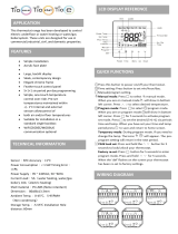
DIGITAL CONTROL OPTIONS D19, D21, D22, AND D23
CONTROL SYSTEM GUIDE FOR Y, J, AND R7 SERIES
⚠ WARNING ⚠
For R7 series packaged rooftop equipment:
FIRE OR EXPLOSION HAZARD
• Failure to follow safety warnings exactly could result in serious injury or property damage.
• Installation and service must be performed by a qualified installer, service agency or the gas
supplier.
• Do not store or use gasoline or other flammable vapors and liquids in the vicinity of this or
any other appliance.
WHAT TO DO IF YOU SMELL GAS
• Do not try to light any appliance.
• Do not touch any electrical switch; do not use any phone in your building.
• Leave the building immediately.
• Immediately call your gas supplier from a neighbor’s phone. Follow the gas suppliers
instructions.
• If you cannot reach your gas supplier, call the fire department.
DO NOT DESTROY. PLEASE READ CAREFULLY. KEEP IN A SAFE PLACE FOR FUTURE REFERENCE.
Supersedes: CP-P125-R7DA-D19-D21-D22-D23 (10-19) PN1024315R1
⚠ DANGER ⚠
For Y and J series packaged rooftop equipment:
This unit contains R-410A high pressure refrigerant. Hazards exist that could result in personal injury
or death. Installation, maintenance, and service should only be performed by an HVAC technician
qualified in R-410A refrigerant and using proper tools and equipment. Due to much higher pressure
of R-410A refrigerant, DO NOT USE service equipment or tools designed for R22 refrigerant.

2
CP-P125-R7DA-D19-D21-D22-D23 (06-20) 1024315-B
TABLE OF CONTENTS
GENERAL INFORMATION ...................................................................3
REFERENCES.............................................................................3
CONTROL SYSTEM ........................................................................4
System Programmable Controller .............................................................4
Display Screen Navigation ..................................................................6
Thermostat Display ........................................................................6
User space-mounted thermostat (option CL78) ................................................6
Optional space temperature and humidity averaging feature......................................7
STATES AND MODES OF OPERATION.........................................................7
D19 (Discharge Air Temperature) Control via Conventional Thermostat or BMS Input ....................8
D19 conventional input states of operation ...................................................8
D19 conventional input modes of operation ...................................................8
D19 (Discharge Air Temperature) Control via CL78 Space Sensor ...................................9
D19 CL78 space sensor states of operation ..................................................9
D19 CL78 space sensor modes of operation ..................................................9
D21 (Discharge Air Temperature) Control with Optional CL78 Space Sensor ..........................10
D21 states of operation .................................................................10
D21 modes of operation .................................................................10
D22 (Discharge Air Temperature) Control via Single Setpoint ......................................11
D22 states of operation .................................................................11
D22 modes of operation .................................................................11
D23 (Space Temperature) Control via Single Setpoint ............................................11
D23 states of operation .................................................................11
D23 modes of operation .................................................................12
UNIT OPERATING CONTROLS ..............................................................12
Temperature and Humidity Control ...........................................................12
Optional neutral air heating sliding scale temperature reset schedule setpoint (D19 and D21 only) .......13
Optional space heating sliding scale temperature reset schedule setpoint (D19 and D21 only) ..........13
Space Temperature and Humidity Setpoint Definitions............................................13
Occupied heating ......................................................................13
Occupied cooling ......................................................................14
Occupied heating cooling (control option D21 only)............................................14
Unoccupied heating ....................................................................14
Unoccupied cooling ....................................................................15
Unoccupied heating cooling (control option D21 only) ..........................................15
Space dehumidification control ...........................................................15
Electric Heat Staging......................................................................16
Electric heat staging—discharge air temperature control (options D19, D21, and D22) ................16
Electric heat staging—space temperature control (option D23)...................................16
Electric heat staging—discharge air temperature control (options D19, D21, and D22 only on R7 series
models with 40kW, 60kW, or 80kW electric heat size)..........................................16
Electric heat staging—space temperature control (option D23 only on R7 series models with 40kW,
60kW, or 80kW electric heat size) .........................................................17
Electric heat stages—options AK5 and AK6 only on R7 series models with 40kW, 60kW, or 80kW
electric heat size) ......................................................................17
Gas Heat Staging ........................................................................18
Gas heat staging—discharge air temperature control (options D19, D21, and D22) ...................18
Gas heat staging—space temperature control (option D23) .....................................18
Mechanical Cooling Staging ................................................................18
Mechanical cooling staging—discharge air temperature control (options D19, D21, and D22) ...........18
Mechanical cooling staging—space temperature control (option D23) .............................19
Mechanical cooling staging—discharge air temperature control (options D19, D21, and D22 only on R7
series models with option AUR2 and cooling size 150 or larger) ..................................19
Mechanical cooling staging—space temperature control (option D23 only on R7 series models with
option AUR2 and cooling size 150 or larger) .................................................19

3
CP-P125-R7DA-D19-D21-D22-D23 (06-20) 1024315-B
Table 1. Related Technical Manuals Available from Factory Distributor
Type Form PN
Y Series
Installation/operation I-Y D300530
Replacement parts P-Y 273651
J Series
Installation I-J D300537
R7 Series
Installation I-R7DA 1024294
Operation O-R7DA 1024295
Replacement parts P-R7DA D303299
GENERAL INFORMATION
This equipment has been tested for capacity and efficiency so as to provide many years of safe and dependable
comfort providing it is properly installed and maintained. With regular maintenance, this equipment will operate
satisfactorily year after year. Abuse, improper use, and/or improper maintenance can shorten the life of the appliance
and create unsafe hazards.
To achieve optimum performance and minimize equipment failure, it is recommended that periodic maintenance be
performed on this equipment. The ability to properly perform maintenance on this equipment requires certain tools
and mechanical skills.
REFERENCES
TABLE OF CONTENTS—CONTINUED
Dehumidification Control ...................................................................20
Space dehumidification .................................................................20
Neutral air dehumidification ..............................................................20
Dehumidification control (options AUR2, RPLE, and RPHE) .....................................20
Energy Recovery Control ..................................................................21
Energy recovery economizer operation (default control setting) ..................................21
Energy recovery continuous operation (optional)..............................................21
Supply Fan Control . . . . . . . . . . . . . . . . . . . . . . . . . . . . . . . . . . . . . . . . . . . . . . . . . . . . . . . . . . . . . . . . . . . . . . . 21
Supply fan control—occupied mode........................................................21
Supply fan control—unoccupied mode . . . . . . . . . . . . . . . . . . . . . . . . . . . . . . . . . . . . . . . . . . . . . . . . . . . . . . . . 22
Exhaust Fan Control . . . . . . . . . . . . . . . . . . . . . . . . . . . . . . . . . . . . . . . . . . . . . . . . . . . . . . . . . . . . . . . . . . . . . . 22
Damper Control..........................................................................22
Airflow Monitoring Options .................................................................24
SAFETIES AND ALARMS...................................................................25
Alarm Conditions.........................................................................25
Alarm Management.......................................................................28
SETUP OF UNIT USING SYSTEM PROGRAMMABLE CONTROLLER ...............................29
Set Date and Time .......................................................................29
Select Unit Occupancy Type and Enable System................................................30
Controller Display Menus ..................................................................31
BACNET NETWORK .......................................................................46
BACnet MSTP Card ......................................................................46
BACnet IP/Ethernet Card ..................................................................47
Modifying BACnet Parameters ..............................................................48
BACnet Points...........................................................................50

4
CP-P125-R7DA-D19-D21-D22-D23 (06-20) 1024315-B
CONTROL SYSTEM
The control system utilizes a factory-installed system programmable controller, an optional field-installed remote
display (wall-mounted or handheld), and an optional field-installed space-mounted thermostat display that allows
for complete access to unit test features, schedules, discharge air setpoints, fan control, alarms, and other unit
operational setpoints. The control system’s features include:
• Local and remote alarming
• Integrated time clock
• Compressor anti-cycle protection and minimum ON/OFF cycle rates
• Protocol support for BACnet®
• Alarm shutdown feature
• Commissioning and test mode functions
• Energy-conscious applications
• TAB menu for creating backup of setpoints
System Programmable Controller
The system programmable controller (see Figure 1) has an integral display that shows unit features and parameters
that can be modified. Refer to Table 2 for a list of control system hardware input points and their descriptions. Refer
to Table 3 for a list of control system hardware output points and their descriptions.
Figure 1. System Programmable Controller with Integral Display
Table 2. Control System Inputs
Input
Terminal
Input Point
Name
Input
Description
Signal
Type
Signal
Range
Always
Active?
Controller Inputs
J23 FB2
Spc_Temp
Space temperature, up to total of 6 inputs
RS-485
communication
—
No
Spc_Humidity
Space humidity, up to total of 6 inputs
U1
OA_Hum_Raw
Outside air humidity 0–10 VDC 0 to 100% RH
U2
OA_Temp_Raw
OAT
Thermistor 10K-2 −35°F to 240°F (−37°C to 115°C)
Yes
U3
EE_Temp_A
Entering evaporator temperature circuit A No
U4
DA_Temp
DAT Yes
U5
CC_Temp
Cooling coil DAT
No
U6
MA_Temp
Mixed air temperature
U7
Bldg_Pressure
Building static pressure
0–10 VDC
−0.5 IN WC through +0.5 IN WC
U8
Duct_Pressure
Duct static pressure 0–2.5 IN WC
U9
Spc_CO2
Space CO
2
0–2000 ppm
U10
ERV_DA_Temp
Energy recovery wheel DAT Thermistor −35°F to 240°F (−37°C to 115°C)
J26 FB2
RA_Temp
Return air temperature
RS-485
communication
—
RA_Humidity
Return air humidity
J26 FB2
EA_Temp
Exhaust air temperature
EA_Humidity
Exhaust air humidity
ID1
SF_Sts
Supply fan status
Dry contact
Open = OFF/close = ON
Yes
ID2
Filter_Sts
Main or ERV dirty filter status No
ID3
Safety_Sts
Safety input status Open = ALARM/close = NORMAL Yes
ID4
Ext_OCC
Occupied mode input
Open = OFF/close = ON No
ID5
Ext_Call_Fan
External fan call input (G)
ID6
Ext_Call_Heat
External heat call input (W1)
ID7
Ext_Call_Cool
External cool call input (Y1)
ID8
Ext_Call_Dh
External dehumidification call input

5
CP-P125-R7DA-D19-D21-D22-D23 (06-20) 1024315-B
Table 3. Control Sysyem Outputs
Output
Terminal
Output Point
Name
Output Description Signal Type Signal Range
Always
Active?
Y1
Damper_Cmd
Damper output command
0–10 VDC
0–100% open
No
Y2
SF_Spd_Cmd
Supply fan speed command 0–100% speed
Y3
Comp_A_Cmd
Compressor A modulation command 1–5 VDC
0–100% capacity
Y4
HX_Mod_Cmd
Gas heating modulation command 2–10 VDC
Electric heating modulation command 0–10 VDC
Y5
RH_A_Cmd
Reheat A modulation command (pump) 1–5 VDC
Reheat A modulation command (valve)
0–10 VDC
Y6
CF_Spd_Cmd
(Y and J series)
Condenser fan speed command Fixed at 90% speed
Vent_Spd_Cmd
(R7 series)
Venter fan speed command 0–100% speed
NO1
SF_Cmd
Supply fan command
24VAC contact Open = OFF/close = ON
Yes
NO2
Comp_B_Cmd
Compressor B command
No
NO3
Comp_C_Cmd
Compressor C command
NO4
Comp_D_Cmd
Compressor D command
NO5
Cond_A_Cmd
Condenser section A command
NO6
Cond_B_Cmd
Condenser section B command
NO7
Alm_Rly_Cmd
Unit general alarm relay command Yes
NO8
HX_Stg1_Cmd
Heating stage 1 command
No
NO9
HX_Stg2_Cmd
Heating stage 2 command
NO10
HX_Stg3_Cmd
Heating stage 3 command
NO11
HX_Stg4_Cmd
Heating stage 4 command
NO12
HX_Stg5_Cmd
Heating stage 5 command
NO13
HX_Stg6_Cmd
Heating stage 6 command
NO14
EF_Cmd
Exhaust fan command
NO15
ERV_Cmd
Energy recovery wheel command
NO16
Preheat_Cmd
Electric preheat command
J25
BMS2
EF_Cmd
Exhaust fan command
RS-485
communication
—
EF_Spd_Cmd
Exhaust fan speed command
Expansion Board Outputs
U7
RH_B_Cmd
Reheat B modulation command (valve)
0–10 VDC
0–100% capacity No
U8
EF_Spd_Cmd
Exhaust fan speed command
U9
Comp_B_Cmd
(R7 series
with AUR2 and
cooling size 150
or larger)
Compressor B modulation command 1–5 VAC
Table 2. Control System Inputs
Input
Terminal
Input Point
Name
Input
Description
Signal
Type
Signal
Range
Always
Active?
ID9
Ext_ Switch_1
External position switch 1
Dry contact
Open = OFF/close = ON
No
ID10
Ext_ Switch_2
External position switch 2
ID11
EF_Sts
Exhaust fan status
ID12
Comp_A_Alarm
Modulating compressor A alarm
ID13
RH_A_Alarm
Modulating reheat compressor A alarm
ID14
Phase_Alarm
Phase protection alarm
ID15
Htr_1_Sts
Gas heater 1 status
Relay N.O.
contact
ID16
Htr_2_Sts
Gas heater 2 status
ID17
Comp_B_Alarm
Modulating compressor B alarm Dry contact
J25
BMS2
EF_Cmd
Exhaust fan command
RS-485
communication
—
EF_Spd_Cmd
Exhaust fan speed command
Expansion Board Inputs
U1
SF_DP
Supply fan differential pressure
0–5 VDC
0–10 IN WC
No
U2
EF_DP
Exhaust fan differential pressure
U3
OA_Flow
Outside airflow 0–15,000 scfm
U4
EE_Temp_B
Entering evaporator temperature circuit B
Carel NTC −58°F to 221°F (−50°C to 105°C)U5
EA_Temp
Exhaust air temperature
U6
SF_Temp
Supply fan temperature
—Continued

6
CP-P125-R7DA-D19-D21-D22-D23 (06-20) 1024315-B
CONTROL SYSTEM—CONTINUED
Display Screen Navigation
Navigation through the controller’s display screens is accomplished by using the function keys (see Figure 2) located
on each side of the controller’s display or the function keys on the remote display.
Figure 2. Function Keys
The position of the cursor on the screen dictates which of the function keys need to be pressed and when. The home
position for the cursor on any screen is located in the upper left-hand corner as shown in Figure 3. Display screen
navigation when the cursor is in the home position is as follows:
• Press up key to go back to previous screen
• Press down key to advance to next screen in alpha-numeric order
• Press enter key to advance cursor to next available modifiable field (see Figure 3)
Display screen navigation when the cursor is positioned on a modifiable field is as follows:
• Press up or down keys to scroll through or toggle
• Press enter key to advance cursor through remaining modifiable fields
• Press enter key again to advance cursor to home position
Test Mode
E.a.2
Test Mode Enable: Off
Time Out: 240
Countdown: 240
Test Mode E.a.2
Test Mode Enable: Off
Time Out: 240
Countdown: 240
HOME POSITION MODIFIABLE FIELD
Figure 3. Cursor Home Position and Modifiable Field Position
Thermostat Display
In its normal state, the thermostat’s user display shows space temperature and humidity, unit status, and time.
User space-mounted thermostat (option CL78)
NOTE: Option CL78 is optional with digital controls D19 and D21, standard with D23, and not
available with D22.
Controls for thermostat option CL78 are listed and described in Table 4 and shown in Figure 4.
Table 4. Thermostat Controls
Button/Dial*
Current State Action
Mode
—
Selects Heat, Cool, or Auto state when pressed
Fan Initiates temporary occupied period when pressed
ON/OFF
Heat, Cool, or Auto Sets unit state to OFF when pressed
Off Sets unit state to previous Heat, Cool, or Auto state when pressed
Setpoint adjustment —
Selects temperature setpoint: press inward on dial once and turn
dial clockwise (increase) or counterclockwise (decrease)
Selects humidity setpoint: press inward on dial twice and turn dial
clockwise (increase) or counterclockwise (decrease)
*See Figure 4.

7
CP-P125-R7DA-D19-D21-D22-D23 (06-20) 1024315-B
Mode Button
Fan Button
ON/OFF Button
Setpoint Adjustment Dial
Figure 4. Thermostat (Option CL78)
Optional space temperature and humidity averaging feature
NOTE: Refer to the installation manual and/or unit wiring drawings for specific wiring informa-
tion.
Up to five space sensors may be added to the control system in addition to the CL78 for a total of six space inputs.
These devices are combination temperature and humidity sensors that operate on a RS-485 communication trunk.
The space averaging sensor addressable DIP switches inside the sensor are shown in Figure 5. The user must set
these addresses accordingly in the field.
Figure 5. Space Averaging Sensor Addressable DIP Switch Settings
STATES AND MODES OF OPERATION
The states and modes of operation for control options D19, D21, D22, and D23 are described in the following
paragraphs. D19, D21, and D22 control Discharge Air Temperature (DAT) as follows: 1) unit supplies neutral air
temperature that does not affect space conditions, 2) unit supplies cold air temperature to provide space cooling,
or 3) unit supplies hot air temperature to provide space heating. D23 controls space temperature.
NOTE: Heating applies only when a unit is ordered with a gas or electric heat section. Heating is
included in all control instructions.

8
CP-P125-R7DA-D19-D21-D22-D23 (06-20) 1024315-B
STATES AND MODES OF OPERATION—CONTINUED
D19 (Discharge Air Temperature) Control via Conventional Thermostat or BMS Input
The D19 control option can operate the supply fan, exhaust fan, dampers, DX cooling, and gas/electric heat to maintain
a set of DAT control setpoints via the conventional thermostat or a Building Maintenance System (BMS) input.
D19 conventional input states of operation
D19 controls the unit in the following conventional states of operation:
• Enable ON: The unit is permitted to operate based on the automatic control system. The unit switches to the
Enable ON state only when the state is manually-selected through the user interface device, unit display, or building
automation network communication point.
• Enable OFF: The unit supply fan and all associated mechanical equipment is OFF in this state. There are no
associated sequences of operation in this state. The unit switches to the OFF state only when the state is manually-
selected through the user interface device, unit display, or building automation network communication point.
Mechanical system selections are permitted only in the Enable OFF state.
• Enable OFF/Alarm: The Enable OFF/Alarm state can occur only from a sequence failure. The unit stops all
mechanical operation until resolution of the failure condition(s). Upon resolving the failure, the unit returns to its
externally-commanded condition. Alarms may also be cleared by resetting power to the unit.
D19 conventional input modes of operation
When the unit is called to operate in the auto, heating, or cooling state(s), D19 controls the unit in one of two
conventional input modes: occupied or unoccupied. The unit will run in occupied or unoccupied mode based on one
of the following three user-selected commands:
• Internal time clock schedule selects occupied or unoccupied mode
• Physical input point (ID4) (contact closed = occupied)
• Building automation (BACnet®) command (option BHB8 required)
Descriptions for the D19 conventional inputs are as follows:
NOTE: The desired input type must be selected. The default is conventional thermostat inputs.
1. Occupied Call (Occupied Contacts (ID4), Optional BMS, or Local Schedule): when occupied, the dampers
follow the occupied mode sequences. When unoccupied, the dampers follow the unoccupied mode sequences
(refer to the Option GF2A (100% outside air): When the unit is indexed to start, the outside air damper is
commanded to open. When the actuator end switch proves the damper is approximately 80% open, unit
operation is permitted. section for specific details).
2. Fan Call (Fan Contacts (ID5) or BMS Input): when the supply fan call is on. the unit supply fan starts. The fan
also automatically starts when the heating, cooling, or dehumidification calls are on. Otherwise, the fan is OFF.
The auto sequence is activated from the fan control when the mechanical cooling and heating contacts are open.
For continuous supply fan operation, the fan call needs to remain on.
3. Heating Call (Heating Contacts (ID6) or BMS Input): when the heating call is on, the supply fan starts and the
heating sequence is enabled. Mechanical heat operates to maintain the heating DAT setpoint listed in Table 5
(Heating Contacts state).
4. Cooling Call (Cooling Contacts (ID7) or BMS Input): when the cooling call is on, the supply fan starts. Mechanical
cooling operates to maintain the cooling unit DAT setpoint listed in Table 5 (Cooling Contacts state).
5. Dehumidification Call (Dehumidification Contacts (ID8) or BMS Input): when the dehumidification call is on
and the cooling and heating contacts are open, the supply fan starts and the unit reheat system is active.
6. Auto Sequence: when the fan call is on and the mechanical cooling, heating, and dehumidification calls are off,
the unit operates in the auto sequence. The unit operates to maintain one of the DAT setpoints listed in Table 5
(Auto Sequence Heat state) based on the Outside Air Temperature (OAT). If both heating and cooling calls are
on, the unit will not turn on any mechanical system until the condition is removed.

9
CP-P125-R7DA-D19-D21-D22-D23 (06-20) 1024315-B
Table 5. D19 Conventional Input Setpoints
State OAT Allowed Discharge Air Control Variable Default Setpoint Range
Heating Contacts
—
Space heating air temperature
DA_SpcHtg_SP
90°F (32°C) 50–140°F (10–60°C)
Cooling Contacts Space cooling air temperature
DA_SpcClg_SP
55°F (12°C) 50–100°F (10–37°C)
Auto Sequence Cool OAT > 65°F Neutral air temperature
DA_NAClg_SP
70°F (21°C) 50–100°F (10–37°C)
Auto Sequence Heat OAT < 65°F Neutral air temperature
DA_NAHtg_SP
70°F (21°C) 50–140°F (20–60°C)
D19 (Discharge Air Temperature) Control via CL78 Space Sensor
The D19 control option can also operate the supply fan, exhaust fan, dampers, DX cooling, and gas or electric
heat to maintain a set of DAT control setpoints via the CL78 space sensor. If the space temperature sensor option
CL78 fails, the logic ignores space requirements and operates to maintain neutral air temperature and neutral air
dehumidification control.
NOTE: Heating applies only when a unit is ordered with a gas or electric heat section.
D19 CL78 space sensor states of operation
D19 control via the CL78 space sensor can switch between states based on the following:
• Controller display (user-selected)
• th-tune space control device (option CL78)
• Building automation (BACnet®) command (option BHB8 required)
• Automatically based on sequence of operation
The unit state of operation is the primary determination of individual component function. The five primary states
are as follows:
1. OFF: the unit supply fan and all associated mechanical equipment is OFF in this state. There are no associated
sequences of operation in this state. The unit switches to the OFF state only when the state is manually-selected
through the th-tune device (option CL78), unit display, or building automation network communication point. Upon
initial power, the OFF state is the default.
2. OFF/Alarm: the OFF/Alarm state can occur only from a sequence failure. The unit switches to this state from
the heating, cooling, or auto state. The unit stops all mechanical operation (unit state OFF) until resolution of the
failure condition(s). Upon resolving the failure, the unit returns to the heating, cooling, or auto state. Alarms may
also be cleared by resetting power to the unit.
3. Heat: the Heat state can be selected from the th-tune device (option CL78), controller display, or BMS. In this
state, the supply fan runs and the mechanical heating and dampers are operated to maintain the heating sequence
of operation. The unit will not automatically switch to other states except for the OFF/Alarm state.
4. Auto: the Auto state can be selected from the th-tune device (option CL78), controller display, or BMS. In this
state, the CL78 space sensor is the primary controlling device for the unit. The unit switches between space
heating and space cooling based on the zone temperature and setpoint. When the space conditions are satisfied,
the unit will maintain neutral DAT. When the unit is providing neutral air temperature, it will switch between two
adjustable neutral setpoints. The switch between the setpoints is based on OAT. When the outdoor air temperature
is below 65°F (18°C), the unit uses the neutral air heating setpoint. When the outdoor air temperature is above
65°F (18°C), the unit uses the neutral air cooling setpoint.
5. Cool: the Cool state can be selected from the th-tune device (option CL78), controller display, or BMS. In this
state, the unit supply fan runs and the mechanical cooling and the dampers are operated to maintain the cooling
sequence of operation. The unit will not automatically switch to other states except for the OFF/Alarm state.
D19 CL78 space sensor modes of operation
When the unit is called to operate in the auto, heating, or cooling state(s), the D19 CL78 space sensor controls the
unit in one of two modes: occupied or unoccupied. The unit will run in occupied or unoccupied mode based on one
of the following three user-selected commands:
• Internal time clock schedule selects occupied or unoccupied mode
• Physical input point (ID4) (contact closed = occupied)
• Building automation (BACnet®) command (option BHB8 required)

10
CP-P125-R7DA-D19-D21-D22-D23 (06-20) 1024315-B
STATES AND MODES OF OPERATION—CONTINUED
D21 (Discharge Air Temperature) Control with Optional CL78 Space Sensor
The D21 control option can operate the supply fan, exhaust fan, dampers, DX cooling, and gas or electric heat to
maintain a set of DAT control setpoints via the CL78 space sensor. If the space temperature sensor option CL78
is not enabled or fails, the logic ignores space requirements and operates to maintain neutral air temperature and
neutral air dehumidification control.
NOTE: Heating applies only when a unit is ordered with a gas or electric heat section.
D21 states of operation
D21 control via the CL78 space sensor can switch between states based on the following:
• Controller display (user-selected)
• th-tune space control device (option CL78)
• Building automation (BACnet®) command (option BHB8 required)
• Automatically based on sequence of operation
The unit state of operation is the primary determination of individual component function. The five primary states
are as follows:
1. OFF: the unit supply fan and all associated mechanical equipment is OFF in this state. There are no associated
sequences of operation in this state. The unit switches to the OFF state only when the state is manually-selected
through the th-tune device (option CL78), unit display, or building automation network communication point. Upon
initial power, the OFF state is the default.
2. OFF/Alarm: the OFF/Alarm state can occur only from a sequence failure. The unit switches to this state from the
heating, cooling, or auto state. The unit will stop all mechanical operation (unit state OFF) until resolution of the
failure condition(s). Upon resolving the failure, the unit returns to the heating, cooling, or auto state. Alarms may
also be cleared by resetting power to the unit.
3. Heat: the Heat state can be selected from the th-tune device (Option CL78), controller display, or BMS. The supply
fan runs and the mechanical heating and dampers are operated to maintain the heating sequence of operation.
The unit will not automatically switch to other states except for the OFF/Alarm state.
4. Auto: the Auto state can be selected from the th-tune device (Option CL78), controller display, or BMS. Upon
initial selection of the auto state, the unit will be in the auto-heating state (if equipped) whenever outdoor air
temperature is below 65°F (18°C). Otherwise, the unit will be in the auto-cooling state. The unit changes to auto-
cooling/auto-heating state when the temperature crosses the changeover setpoint for more than 15 minutes or
is more than 5°F (2.8°C) beyond the changeover setpoint.
NOTE: The unit switches between heating and cooling based upon OAT. Space temperature
does not dictate heating or cooling mode.
5. Cool: the Cool state can be selected from the th-tune device (Option CL78), controller display, or BMS. In this
state, the unit supply fan runs and the mechanical cooling and dampers are operated to maintain the cooling
sequence of operation. The unit will not automatically switch to other states except for the OFF/Alarm state.
D21 modes of operation
When the unit is called to operate in the auto, heating, or cooling state(s), the D21 CL78 space sensor controls the
unit in one of two modes: occupied or unoccupied. The unit will run in occupied or unoccupied mode based on one
of the following three user-selected commands:
• Internal time clock schedule selects occupied or unoccupied mode
• Physical input point (ID4) (contact closed = occupied)
• Building automation (BACnet®) command (option BHB8 required)

11
CP-P125-R7DA-D19-D21-D22-D23 (06-20) 1024315-B
D22 (Discharge Air Temperature) Control via Single Setpoint
The D22 control option allows the end user to set the desired DAT for the unit via a single setpoint. The control
operates the supply fan, dampers, exhaust fan, DX cooling, and gas or electric heat to maintain the DAT control
setpoint. The setpoint variable, when selected, becomes the single discharge air setpoint for the unit. Table 6 lists
and describes the two variables that can be selected.
Table 6. D22 Discharge Air Setpoint Variables
Variable
Name
Variable
Description
Default
Setpoint
Range
DA_Loc_SP
DAT local setpoint: accessible from unit display and allows unit to operate stand-
alone without need for third-party BMS system
70°F
(21°C)
50–140°F
(10–60°C)
DA_BMS_SP
DAT BMS setpoint: intended for use by third-party BMS system for external
temperature setpoint adjustment
—
50–140°F
(10–60°C)
D22 states of operation
D22 controls the unit in the following states of operation:
• Enable ON: The unit is permitted to operate based on the automatic control system. The unit switches to the
Enable ON state only when the state is manually-selected through the user interface device, unit display, or building
automation network communication point.
• Enable OFF: The unit supply fan and all associated mechanical equipment is OFF in this state. There are no
associated sequences of operation in this state. The unit switches to the OFF state only when the state is manually-
selected through the user interface device, unit display, or building automation network communication point.
Mechanical system selections are permitted only in the Enable OFF state.
• Enable OFF/Alarm: The Enable OFF/Alarm state can occur only from a sequence failure. The unit stops all
mechanical operation until resolution of the failure condition(s). Upon resolving the failure, the unit returns to its
externally-commanded condition. Alarms may also be cleared by resetting power to the unit.
D22 modes of operation
When the unit is called to operate in the auto, heating, or cooling state(s), D22 controls the unit in one of two modes:
occupied or unoccupied. The unit will run in occupied or unoccupied mode based on one of the following three user-
selected commands:
• Internal time clock schedule selects occupied or unoccupied mode
• Physical input point (ID4) (contact closed = occupied)
• Building automation (BACnet®) command (option BHB8 required)
D23 (Space Temperature) Control via Single Setpoint
The D23 control option allows the end user to set the desired space temperature for the unit via a single setpoint.
The control operates the supply fan, dampers, exhaust fan, DX cooling, and gas or electric heat to maintain space
temperature. If the space temperature sensor option CL78 fails, the logic ignores space temperature requirements,
shuts down the heating and cooling functions, and operate only with blowers.
D23 states of operation
D23 control can switch between states based on the following:
• Controller display (user-selected)
• th-tune space control device (option CL78)
• Building automation (BACnet®) command (option BHB8 required)
• Automatically based on sequence of operation
The unit state of operation is the primary determination of individual component function. The five primary states
are as follows:
1. OFF: the unit supply fan and all associated mechanical equipment is OFF in this state. There are no associated
sequences of operation in this state. The unit switches to the OFF state only when the state is manually-selected
through the th-tune device (option CL78), unit display, or building automation network communication point. Upon
initial power, the OFF state is the default.

12
CP-P125-R7DA-D19-D21-D22-D23 (06-20) 1024315-B
Table 7. Temperature and Humidity Control Setpoints
Applicable Control
Option Code
Variable
Name
Variable
Description
Default
Setpoint
Range
D19, D21
DA_SpcHtg_SP
DAT space heating setpoint
90°F
(32°C)
50–140°F
(10–60°C)
DA_SpcClg_SP
DAT space cooling setpoint
55°F
(12°C)
50–100°F
(10–37°C)
DA_NAHtg_SP
DAT neutral heating setpoint
70°F
(21°C)
50–140°F
(20–60°C)
DA_NAClg_SP
DAT neutral cooling setpoint
70°F
(21°C)
50–100°F
(10–37°C)
D21
DA_SpcHtCl_SP
DAT space heat mode cooling setpoint
55°F
(12°C)
50–100°F
(10–37°C)
D22
DA_Loc_SP
DAT local setpoint
70°F
(21°C)
50–140°F
(10–60°C)
DA_BMS_SP
DAT BMS setpoint —
50–140°F
(10–60°C)
RPLE, RPHE, AUR2
DA_Dh_SP
DAT dehumidification setpoint
70°F
(21°C)
50–100°F
(10–37°C)
CC_DA_SP
Cooling coil dehumidification DAT setpoint
52°F
(11°C)
45–80°F
(7–26°C)
D19, D21, D23
SpcTempSP
Space temperature setpoint
72°F
(22°C)
65–85°F
(18–29°C)
SpcHumSP
Space humidity setpoint 52% 35–75%
STATES AND MODES OF OPERATION—CONTINUED
2. OFF/Alarm: the OFF/Alarm state can occur only from a sequence failure. The unit switches to this state from the
heating, cooling, or auto state. The unit will stop all mechanical operation (unit state OFF) until resolution of the
failure condition(s). Upon resolving the failure, the unit returns to the heating, cooling, or auto state. Alarms may
also be cleared by resetting power to the unit.
3. Heat: the Heat state can be selected from the th-tune device (Option CL78), controller display, or BMS. The supply
fan runs and the mechanical heating and dampers are operated to maintain the heating sequence of operation.
The unit will not automatically switch to other states except for the OFF/Alarm state.
4. Auto: the Auto state can be selected from the th-tune device (Option CL78), controller display, or BMS. In this
state, the supply fan runs and the mechanical heating/cooling and dampers are operated to maintain the automatic
sequence of operation. In the auto sequence the unit switches between heating and cooling to maintain the space
temperature setpoint.
5. Cool: the Cool state can be selected from the th-tune device (Option CL78), controller display, or BMS. In this
state, the unit supply fan runs and the mechanical cooling and dampers are operated to maintain the cooling
sequence of operation. The unit will not automatically switch to other states except for the OFF/Alarm state.
D23 modes of operation
When the unit is called to operate in the auto, heating, or cooling state(s), D23 controls the unit in one of two modes:
occupied or unoccupied. The unit will run in occupied or unoccupied mode based on one of the following three user-
selected commands:
• Internal time clock schedule selects occupied or unoccupied mode
• Physical input point (ID4) (contact closed = occupied)
• Building automation (BACnet®) command (option BHB8 required)
UNIT OPERATING CONTROLS
The operating controls for the supply fan, dampers, heating systems, cooling systems, temperature and humidity
control are described in the following paragraphs.
Temperature and Humidity Control
Selected temperature and humidity setpoints are user-adjustable from the unit display, optional wall-mounted user
interface, or optional BMS card. Depending on the state, mode, and control option, temperature and humidity are
controlled based on the setpoints listed in Table 7.

13
CP-P125-R7DA-D19-D21-D22-D23 (06-20) 1024315-B
Optional neutral air heating sliding scale temperature reset schedule setpoint (D19 and D21
only)
For control options D19 and D21, the user can select a reset schedule for the discharge setpoint used when in
neutral air heating mode. Table 8 lists reset schedule tempeature setpoints (see Figure 6).
Figure 6. Reset Schedule Air Temperatures
Optional space heating sliding scale temperature reset schedule setpoint (D19 and D21 only)
For control options D19 and D21, the user can also select a reset schedule for the discharge setpoint used when in
space heating mode. Table 8 lists reset schedule tempeature setpoints (see Figure 6).
Space Temperature and Humidity Setpoint Definitions
The base space temperature setpoint (SpcTempSP) is 72°F (22°C), and the base space humidity setpoint is 52%
(refer to Table 7). The following calculations are used to establish base setpoints that are then used to calculate
setpoints for the heating/cooling/dehumidification modes that follow.
SpcTempSP − SpcHtgDB = SpcHtgSP
• base space heating dead band (SpcHtgDB) = 1°F (0.4°C)
• base space heating setpoint (SpcHtgSP) = 71°F (22°C)
SpcTempSP + SpcClgDB = SpcClgSP
• base space cooling dead band (SpcClgDB) = 1°F (0.4°C)
• base space cooling setpoint (SpcClgSP) = 73°F (23°C)
Occupied heating
When the unit is in the occupied mode, the space heating setpoint (SpcHtgSP) is the space effective heating setpoint
(SpcEffHtgSp).
• space effective heating setpoint (SpcEffHtgSp) = 71°F (22°C)
SpcEffHtgSp − SpcHtgOnDiff = actual space heating on value
• space heating ON differential (SpcHtgOnDiff) = 1°F (0.4°C)
• actual space heating on value = 70°F (21°C)
When the space temperature is ≤70°F (21°C), the Space Heating Mode is ON.
SpcEffHtgSp + SpcHtgOffDiff = actual space heating off value
• space heating OFF differential (SpcHtgOffDiff) = 1°F (0.4°C)
• actual space heating off value = 72°F (22°C)
When the space temperature is ≥72°F (22°C), the Space Heating Mode is OFF.
Table 8. Reset Schedule Temperature Setpoints
Neutral Air Heating Mode Space Heating Mode
OAT DAT OAT DAT
30°F (−1.1°C) 75°F (23.8°C)
30°F (−1.1°C) 120°F (48.9°C)
65°F (18.3°C) 65°F (18.3°C) 65°F (18.3°C) 90°F (32.2°C)
Neutral Air Heating Mode Space Heating Mode

14
CP-P125-R7DA-D19-D21-D22-D23 (06-20) 1024315-B
UNIT OPERATING CONTROLS—CONTINUED
Space Temperature and Humidity Setpoint Definitions—Continued
Occupied cooling
When the unit is in the occupied mode, the space cooling setpoint (SpcClgSP) is the space effective cooling setpoint
(SpcEffClgSp).
• space effective cooling setpoint (SpcEffClgSp) = 73°F (23°C)
SpcEffClgSp + SpcClgOnDiff = actual space cooling on value
• space cooling ON differential (SpcHtgOnDiff) = 1°F (0.4°C)
• actual space cooling on value = 74°F (23°C)
When the space temperature is ≥74°F (23°C), the Space Cooling Mode is ON.
SpcEffClgSp − SpcClgOffDiff = actual space cooling off value
• space cooling OFF differential (SpcClgOffDiff) = 1°F (0.4°C)
• actual space cooling off value = 72°F (22°C)
When the space temperature is ≤72°F (22°C), the Space Cooling Mode is OFF.
Occupied heating cooling (control option D21 only)
When the unit is in the occupied heating cooling mode, the space cooling setpoint (SpcClgSP) is the space effective
cooling setpoint (SpcEffClgSp).
• space effective cooling setpoint (SpcEffClgSp) = 73°F (23°C)
When the unit is set to auto heating, option D21 controls space cooling as follows:
SpcEffClgSp + SpcHCOnDiff = actual space cooling on value
• space heating cooling ON differential (SpcHCOnDiff) = 1°F (0.4°C)
• actual space cooling on value = 74°F (23°C)
When the space temperature is ≥74°F (23°C), the Space Heating Cooling Mode is ON.
SpcEffClgSp − SpcHCOffDiff = actual space cooling off value
• space heating cooling OFF differential (SpcHCOffDiff) = 1°F (0.4°C)
• actual space cooling off value = 72°F (22°C)
When the space temperature is ≤72°F (22°C), the Space Heating Cooling Mode is OFF.
Unoccupied heating
NOTE: By default, unoccupied heating and cooling are enabled when the system is equipped
with a CL78 space sensor. If unoccupied heating or cooling is not desired, set the Ena_Unocc_
Spc variable to OFF.
When the unit is in the unoccupied mode, heating is determined by the space effective heating setpoint (SpcEffHtgSp).
SpcHtgSP − SpcHtgUnoOs = SpcEffHtgSp
• space heating unoccupied offset setpoint (SpcHtgUnoOs) = 8°F (4°C)
• space effective heating setpoint (SpcEffHtgSp) = 63°F (17°C)
SpcEffHtgSp − SpcHtgOnDiff = actual space heating on value
• space heating ON differential (SpcHtgOnDiff) = 1°F (0.4°C)
• actual space heating on value = 62°F (17°C)
When the actual space temperature is ≤62°F (17°C), the Space Heating Mode is ON.
SpcEffHtgSp + UnoHtgOffDiff = actual space heating off value
• unoccupied space heating OFF differential (UnoHtgOffDiff) = 4°F (2.2°C)
• actual space heating off value = 67°F (19°C)
When the space temperature is ≥67°F (19°C), the Space Heating Mode is OFF.

15
CP-P125-R7DA-D19-D21-D22-D23 (06-20) 1024315-B
Unoccupied cooling
When the unit is in the unoccupied mode, cooling is determined by the space effective cooling setpoint (SpcEffClgSp).
SpcClgSP + SpcClgUnoOs = SpcEffClgSp
• space cooling unoccupied offset setpoint (SpcClgUnoOs) = 8°F (4°C)
• space effective cooling setpoint (SpcEffClgSp) = 81°F (27°C)
SpcEffClgSp + SpcClgOnDiff = actual space cooling on value
• space cooling ON differential (SpcClgOnDiff) = 1°F (0.4°C)
• actual space cooling on value = 82°F (28°C)
When the space temperature is ≥82°F (28°C), the Space Cooling Mode is ON.
SpcEffClgSp − UnoClgOffDiff = actual space cooling off value
• unoccupied space cooling OFF differential (UnoClgOffDiff) = 4°F (2.2°C)
• actual space cooling off value = 77°F (25°C)
When the space temperature is ≤77°F (25°C), the Space Cooling Mode is OFF.
Unoccupied heating cooling (control option D21 only)
When the unit is in the unoccupied mode and it is set to auto heating, cooling is determined by the space effective
cooling setpoint (SpcEffClgSp).
SpcClgSP + SpcClgUnoOs = SpcEffClgSp
• space cooling unoccupied offset setpoint (SpcClgUnoOs) = 8°F (4°C)
• space effective cooling setpoint (SpcEffClgSp) = 81°F (27°C)
SpcEffClgSp + SpcHCOnDiff = actual space cooling on value
• space heating cooling ON differential (SpcHCOnDiff) = 1°F (0.4°C)
• actual space cooling on value = 82°F (28°C)
When the space temperature is ≥82°F (28°C), the Space Heating Cooling Mode is ON.
SpcEffClgSp − UnoHCOffDiff = actual space cooling off value
• unoccupied space heating cooling OFF differential (UnoHCOffDiff) = 4°F (2.2°C)
• actual space cooling off value = 77°F (25°C)
When the space temperature is ≤77°F (25°C), the Space Cooling Mode is OFF.
Space dehumidification control
• space humidity setpoint (SpcHumSp) = 52%
SpcHumSp + SpcDhOnDiff = actual space dehumidification on value
• space dehumidification ON differential (SpcDhOnDiff) = 3%
• actual space dehumidification on value = 55%
When the space humidity is ≥55°F, the Space Dehumidification Mode is ON.
SpcHumSp − SpcDhOffDiff = actual space dehumidification off value
• space dehumidification OFF differential (SpcDhOffDiff) = 2%
• actual space dehumidification off value = 50%
When the space humidity is ≤50°F, the Space Dehumidification Mode is OFF.

16
CP-P125-R7DA-D19-D21-D22-D23 (06-20) 1024315-B
UNIT OPERATING CONTROLS—CONTINUED
Electric Heat Staging
Electric heat staging—discharge air temperature control (options D19, D21, and D22)
Electric heat staging will start when the DAT is 5°F (2.8°C) below the active setpoint and the OAT is below the heating
lockout setpoint. The Proportional Integral Derivative (PID) loop will activate and the unit will stage (refer to Table
9) to maintain the active discharge air setpoint. The unit may be equipped with up to six stages of electric heat. The
number of stages and the modulated capacity control are determined by unit size and/or option.
Table 9. Electric Heat Staging—Discharge Air Temperature Control (Options D19, D21, and D22)
Stage*
Output
Increase
Interstage Timing
Activate**
Decrease
Interstage Timing
Deactivate**
1 NO6 = ON —
DAT 5°F (2.8°C) below setpoint (Y4
modulates SCR via heating demand)
15 minutes
Heating demand < 2.5% and DAT 5°F
(2.8°C) above setpoint
2 NO7 = ON
5 minutes
Heating demand > 70% and DAT 5°F
(2.8°C) below setpoint
Heating demand < 5% and DAT 5°F
(2.8°C) above setpoint
3 NO8 = ON
Heating demand > 75% and DAT 5°F
(2.8°C) below setpoint
Heating demand < 10% and DAT 5°F
(2.8°C) above setpoint
4 NO9 = ON
Heating demand > 80% and DAT 5°F
(2.8°C) below setpoint
Heating demand < 20% and DAT 5°F
(2.8°C) above setpoint
5 NO10 = ON
Heating demand > 85% and DAT 5°F
(2.8°C) below setpoint
Heating demand < 30% and DAT 5°F
(2.8°C) above setpoint
6 NO11 = ON
Heating demand > 90% and DAT 5°F
(2.8°C) below setpoint
Heating demand < 40% and DAT 5°F
(2.8°C) above setpoint
*All stages have adjustable minimum ON and OFF times.
**PID loop control: all statements must be true to activate or deactivate.
Electric heat staging—space temperature control (option D23)
Electric heat staging will start when the unit enters the Space Heating mode and the OAT is below the heating lockout
setpoint. The PID loop will activate and the unit will stage (refer to Table 10) to maintain the space temperature
setpoint. The unit may be equipped with up to six stages of electric heat. The number of stages and the modulated
capacity control are determined by unit size and/or option.
Table 10. Electric Heat Staging—Space Temperature Control (Option D23)
Stage*
Output
Increase
Interstage Timing
Activate** Deactivate**
1 NO6 = ON —
Space Heating mode ON
(Y4 modulates SCR via heating demand)
Space Heating mode OFF
2 NO7 = ON
5 minutes
Space Heating mode ON and
heating demand > 70%
Space Heating mode OFF or
heating demand < 5%
3 NO8 = ON
Space Heating mode ON and
heating demand > 75%
Space Heating mode OFF or
heating demand < 10%
4 NO9 = ON
Space Heating mode ON and
heating demand > 80%
Space Heating mode OFF or
heating demand < 20%
5 NO10 = ON
Space Heating mode ON and
heating demand > 85%
Space Heating mode OFF or
heating demand < 30%
6 NO11 = ON
Space Heating mode ON and
heating demand > 90%
Space Heating mode OFF or
heating demand < 40%
*All stages have adjustable minimum ON and OFF times.
**PID loop control: all statements must be true to activate or deactivate.
Electric heat staging—discharge air temperature control (options D19, D21, and D22 only on R7
series models with 40kW, 60kW, or 80kW electric heat size)
Electric heat staging will start when the DAT is 5°F (2.8°C) below the active setpoint and the OAT is below the heating
lockout setpoint. The Proportional Integral Derivative (PID) loop will activate and the unit will stage (refer to Table
11) to maintain the active discharge air setpoint. The unit may be equipped with up to six stages of electric heat. The
number of stages and the modulated capacity control are determined by unit size and/or option.

17
CP-P125-R7DA-D19-D21-D22-D23 (06-20) 1024315-B
Table 11. Electric Heat Staging—Discharge Air Temperature Control (Options D19, D21, and D22 Only on
R7 Series Models with 40kW, 60kW, or 80kW Electric Heat Size)
Stage*
Increase
Interstage Timing
Activate**
Decrease
Interstage Timing
Deactivate**
1 —
DAT 5°F (2.8°C) below setpoint (Y4
modulates SCR via heating demand)
15 minutes
Heating demand < 2.5% and DAT 5°F
(2.8°C) above setpoint
2
5 minutes
Heating demand > 70% and DAT 5°F
(2.8°C) below setpoint
Heating demand < 5% and DAT 5°F (2.8°C)
above setpoint
3
Heating demand > 75% and DAT 5°F
(2.8°C) below setpoint
Heating demand < 10% and DAT 5°F
(2.8°C) above setpoint
4
Heating demand > 80% and DAT 5°F
(2.8°C) below setpoint
Heating demand < 20% and DAT 5°F
(2.8°C) above setpoint
5
Heating demand > 85% and DAT 5°F
(2.8°C) below setpoint
Heating demand < 30% and DAT 5°F
(2.8°C) above setpoint
6
Heating demand > 90% and DAT 5°F
(2.8°C) below setpoint
Heating demand < 40% and DAT 5°F
(2.8°C) above setpoint
7
Heating demand > 95% and DAT 5°F
(2.8°C) below setpoint
Heating demand < 50% and DAT 5°F
(2.8°C) above setpoint
*All stages have adjustable minimum ON and OFF times.
**PID loop control: all statements must be true to activate or deactivate.
Electric heat staging—space temperature control (option D23 only on R7 series models with
40kW, 60kW, or 80kW electric heat size)
Electric heat staging will start when the unit enters the Space Heating mode and the OAT is below the heating lockout
setpoint. The PID loop will activate and the unit will stage (refer to Table 12) to maintain the space temperature
setpoint. The unit may be equipped with up to six stages of electric heat. The number of stages and the modulated
capacity control are determined by unit size and/or option.
Table 12. Electric Heat Staging—Space Temperature Control (Option D23 Only on R7 Series Models with
40kW, 60kW, or 80kW Electric Heat Size)
Stage*
Increase
Interstage Timing
Activate** Deactivate**
1 —
Space Heating mode ON (Y4 modulates SCR via
heating demand)
Space Heating mode OFF
2
5 minutes
Space Heating mode ON and heating demand > 70% Space Heating mode OFF or heating demand < 5%
3 Space Heating mode ON and heating demand > 75% Space Heating mode OFF or heating demand < 10%
4 Space Heating mode ON and heating demand > 80% Space Heating mode OFF or heating demand < 20%
5 Space Heating mode ON and heating demand > 85% Space Heating mode OFF or heating demand < 30%
6 Space Heating mode ON and heating demand > 90% Space Heating mode OFF or heating demand < 40%
7 Space Heating mode ON and heating demand > 95% Space Heating mode OFF or heating demand < 50%
*All stages have adjustable minimum ON and OFF times.
**PID loop control: all statements must be true to activate or deactivate.
Electric heat stages—options AK5 and AK6 only on R7 series models with 40kW, 60kW, or 80kW
electric heat size)
Table 13. Electric Heat Stages—Options AK5 and AK6 Only on R7 Series Models with 40kW, 60kW, or
80kW Electric Heat Size
Heating
Size
Output
Capacity
(kW)
Stage 1 Stage 2 Stage 3 Stage 4 Stage 5 Stage 6 Stage 7
40kW
NO8 (SCR circuit) 10 ON ON ON ON — — —
NO9 10 OFF ON OFF ON — — —
NO10 20 OFF OFF ON ON — — —
60kW
NO8 (SCR circuit) 10 ON ON ON ON ON ON —
NO9 10 OFF ON OFF ON OFF ON —
NO10 20 OFF OFF ON ON ON ON —
NO11 20 OFF OFF OFF OFF ON ON —
80kW
NO8 (SCR circuit) 10 ON ON ON ON ON ON ON
NO9 10 OFF ON OFF ON OFF ON ON
NO10 20 OFF OFF ON ON ON ON ON
NO11 20 OFF OFF OFF OFF ON ON ON
NO12 20 OFF OFF OFF OFF OFF OFF ON

18
CP-P125-R7DA-D19-D21-D22-D23 (03-19) PN1024315R0
Table 14. Gas Heat Staging—Discharge Air Temperature Control (Options D19, D21, and D22)
Stage*
Output
Increase
Interstage Timing
Activate**
Decrease
Interstage Timing
Deactivate**
1
NO6 = ON
(refer to
NOTEs 1–3)
—
DAT 5°F (2.8°C) below setpoint (Y4
modulates heat exchanger 1 via
heating demand)
5 or 15 minutes
(refer to NOTE 4)
Heating demand < 2.5% and DAT 5°F
(2.8°C) above setpoint
2 NO7 = ON
5 minutes
Heating demand > 70% and DAT 5°F
(2.8°C) below setpoint
Heating demand < 5% and DAT 5°F
(2.8°C) above setpoint
3 NO8 = ON
Heating demand > 75% and DAT 5°F
(2.8°C) below setpoint
Heating demand < 10% and DAT 5°F
(2.8°C) above setpoint
4 NO9 = ON
Heating demand > 80% and DAT 5°F
(2.8°C) below setpoint
Heating demand < 20% and DAT 5°F
(2.8°C) above setpoint
*All stages have adjustable minimum ON and OFF times.
**PID loop control: all statements must be true to activate or deactivate.
NOTE 1: Y series light OFF (Y4 gas valve modulation value for natural gas and propane = 30% duration 30 seconds).
NOTE 2: R7 series light OFF (Y4 gas valve modulation value for natural gas and propane = 65% duration 60 seconds).
NOTE 3: Y4 modulation applies only to units equipped with modulating gas valves.
NOTE 4: 5-minute timer for non-modulated systems. 15-minute timer used on modulated systems to allow capacity control to achieve low fire
rate.
Gas heat staging—space temperature control (option D23)
Gas heat staging will start when the unit enters the Space Heating mode and the OAT is below the heating lockout
setpoint. The PID loop will activate and the unit will stage (refer to Table 15) to maintain the space temperature
setpoint. The unit may be equipped with up to four stages of gas heat. The number of stages and the modulated
capacity control are determined by unit size and/or option.
UNIT OPERATING CONTROLS—CONTINUED
Gas Heat Staging
Gas heat staging—discharge air temperature control (options D19, D21, and D22)
Gas heat staging will start when the DAT is 5°F (2.8°C) below the active setpoint and the OAT is below the heating
lockout setpoint. The PID loop will activate and the unit will stage (refer to Table 14) to maintain the active discharge
air setpoint. The unit may be equipped with up to four stages of gas heat. The number of stages and the modulated
capacity control are are determined by unit size and/or option.
Table 15. Gas Heat Staging—Space Temperature Control (Option D23)
Stage*
Output
Increase
Interstage Timing
Activate** Deactivate**
1
NO6 = ON
(refer to
NOTEs 1–3)
—
Space Heating mode ON
(Y4 Modulates heat exchanger 1 via heating demand)
Space Heating mode OFF
2 NO7 = ON
5 minutes
Space Heating mode ON and
heating demand > 70%
Space Heating mode OFF or
heating demand < 5%
3 NO8 = ON
Space Heating mode ON and
heating demand > 75%
Space Heating mode OFF or
heating demand < 10%
4 NO9 = ON
Space Heating mode ON and
heating demand > 80%
Space Heating mode OFF or
heating demand < 20%
*All stages have adjustable minimum ON and OFF times.
**PID loop control: all statements must be true to activate or deactivate.
NOTE 1: Y series light OFF (Y4 gas valve modulation value for natural gas and propane = 30% duration 30 seconds).
NOTE 2: R7 series light OFF (Y4 gas valve modulation value for natural gas and propane = 65% duration 60 seconds).
NOTE 3: Y4 modulation applies only to units equipped with modulating gas valves.
Mechanical Cooling Staging
Mechanical cooling staging—discharge air temperature control (options D19, D21, and D22)
Mechanical cooling staging will start when the DAT is 5°F (2.8°C) above the active setpoint and the OAT is above
the cooling lockout setpoint. The PID loop will activate and the unit will stage (refer to Table 16) to maintain the
active discharge air setpoint. The unit may be equipped with up to two stages of cooling. The number of stages is
determined by unit size and/or option.

19
CP-P125-R7DA-D19-D21-D22-D23 (03-19) PN1024315R0
Mechanical cooling staging—space temperature control (option D23)
Mechanical cooling staging will start when the unit enters the Space Cooling mode and the OAT is above the cooling
lockout setpoint. The PID loop will activate and the unit will stage (refer to Table 17) to maintain the space temperature
setpoint. The unit may be equipped with up to two stages of cooling. The number of stages is determined by unit
size and/or option.
Table 16. Mechanical Cooling Staging—Discharge Air Temperature Control (Options D19, D21, and D22)
Stage*
Output
Compressor/
Condenser
Interstage
Timing
Activate** Deactivate**
1 Y3 A
5 minutes
DAT 5°F (2.8°C) above setpoint (circuit
A modulates with cooling demand)
<10% modulation and DAT 5°F
(2.8°C) below setpoint
2 NO2 A and B
>70% modulation and DAT 5°F (2.8°C)
above setpoint
<50% modulation and DAT 5°F
(2.8°C) below setpoint
Condenser A
(refer to NOTE 1)
NO5 Cond_Sec_A
—
When Y3 > 0% When Y3 = 0%, OFF
Condenser B NO6 Cond_Sec_B When NO2 = ON When NO2 = OFF
*All stages have adjustable minimum ON and OFF times.
**PID loop control: all statements must be true to activate or deactivate.
NOTE 1: R7 series units use condensor section A only and NO5 activates with either compressor.
Table 17. Mechanical Cooling Staging—Space Temperature Control (Option D23)
Stage*
Output
Compressor/
Condenser
Interstage
Timing
Activate** Deactivate**
1 Y3 A
5 minutes
Space Cooling mode ON (circuit A
modulates with cooling demand)
Space Cooling mode OFF
2 NO2 A and B
Space Cooling mode ON and
>70% modulation
Space Cooling mode OFF or
<50% modulation
Condenser A
(refer to NOTE 1)
NO5 Cond_Sec_A
—
When Y3 > 0% When Y3 = 0%, OFF
Condenser B NO6 Cond_Sec_B When NO2 = ON When NO2 = OFF
*All stages have adjustable minimum ON and OFF times.
**PID loop control: all statements must be true to activate or deactivate.
NOTE 1: R7 series units use condensor section A only and NO5 activates with either compressor.
Mechanical cooling staging—space temperature control (option D23 only on R7 series models
with option AUR2 and cooling size 150 or larger)
Mechanical cooling staging will start when the unit enters the Space Cooling mode and the OAT is above the cooling
lockout setpoint. The PID loop will activate and the unit will stage (refer to Table 19) to maintain the space temperature
setpoint. The unit may be equipped with up to two stages of cooling. The number of stages is determined by unit
size and/or option.
Table 18. Mechanical Cooling Staging—Discharge Air Temperature Control
(Options D19, D21, and D22 Only on R7 Series Models with Option AUR2 and Cooling Size 150 or Larger)
Stage*
Output
Compressor/
Condenser
Interstage
Timing
Activate** Deactivate**
1 Y3 A
5 minutes
DAT 5°F (2.8°C) above setpoint (circuit
A modulates with cooling demand)
<10% modulation and DAT 5°F
(2.8°C) below setpoint
2 U9 A and B
>95% A modulation and DAT 5°F
(2.8°C) above setpoint
<10% B modulation and DAT
5°F (2.8°C) below setpoint
Condenser A
(refer to NOTE 1)
NO5 Cond_Sec_A
—
When Y3 > 0% When Y3 = 0%, OFF
Condenser B NO6 Cond_Sec_B When NO2 = ON When NO2 = OFF
*All stages have adjustable minimum ON and OFF times.
**PID loop control: all statements must be true to activate or deactivate.
NOTE 1: R7 series units use condensor section A only and NO5 activates with either compressor.
Mechanical cooling staging—discharge air temperature control (options D19, D21, and D22 only
on R7 series models with option AUR2 and cooling size 150 or larger)
Mechanical cooling staging will start when the DAT is 5°F (2.8°C) above the active setpoint and the OAT is above
the cooling lockout setpoint. The PID loop will activate and the unit will stage (refer to Table 18) to maintain the
active discharge air setpoint. The unit may be equipped with up to two stages of cooling. The number of stages is
determined by unit size and/or option.

20
CP-P125-R7DA-D19-D21-D22-D23 (06-20) 1024315-B
Table 19. Mechanical Cooling Staging—Space Temperature Control
(Option D23 Only on R7 Series Models with Option AUR2 and Cooling Size 150 or Larger)
Stage*
Output
Compressor/
Condenser
Interstage
Timing
Activate** Deactivate**
1 Y3 A
5 minutes
Space Cooling mode ON (circuit A
modulates with cooling demand)
Space Cooling mode OFF
2 U9 A and B
Space Cooling mode ON and
>95% A modulation
Space Cooling mode OFF or
<10% B modulation
Condenser A
(refer to NOTE 1)
NO5 Cond_Sec_A
—
When Y3 > 0% When Y3 = 0%, OFF
Condenser B NO6 Cond_Sec_B When NO2 = ON When NO2 = OFF
*All stages have adjustable minimum ON and OFF times.
**PID loop control: all statements must be true to activate or deactivate.
NOTE 1: R7 series units use condensor section A only and NO5 activates with either compressor.
UNIT OPERATING CONTROLS—CONTINUED
Mechanical Cooling Staging—Continued
Mechanical cooling staging—space temperature control (option D23 only on R7 series models
with option AUR2 and cooling size 150 or larger)—Continued
Dehumidification Control
Space dehumidification
All of the following conditions must be true for the unit to enter the Space Dehumidification mode:
1. Outdoor air temperature is above reheat low lockout setpoint (58°F (14°C) reheat lockout, range 50–100°F
(10–37°C) drybulb)
2. Outdoor air temperature is below reheat high lockout setpoint (100°F (37°C) reheat high lockout, range 50–120°F
(10–48°C) drybulb)
3. Space Cooling mode is not active
4. Unit cooling coil sensor is not in failed condition
5. Space dehumidification call is active
6. Reheat pump controller must not be in alarm condition (RPLE and RPHE units only)
Neutral air dehumidification
All of the following conditions must be true for the unit to enter the Neutral Air Dehumidification mode:
1. Outdoor air temperature is above reheat low lockout setpoint (58°F (14°C) reheat lockout, range 50–100°F
(10–37°C) drybulb)
2. Outdoor air temperature is below reheat high lockout setpoint (100°F (37°C) reheat high lockout, range 50–120°F
(10–48°C) drybulb)
3. Unit outside air humidity sensor is not in failed condition
4. Unit cooling coil sensor is not in failed condition
5. Outside air dewpoint > 58°F (14°C) (options D19, D21, and D22 only)
6. Space dehumidification call is not active
7. Space Cooling mode is not active
8. For units selected with D22, active discharge air setpoint must be 15°F (8.3°C) greater than cooling coil discharge
setpoint
9. Reheat pump controller must not be in alarm condition (RPLE and RPHE units only)
Dehumidification control (options AUR2, RPLE, and RPHE)
When either the Space Dehumidification or Neutral Air Dehumidification mode is active, the main evaporator
compressor(s) will be enabled to maintain a 52°F (11°C) cooling coil discharge setpoint and will use the U5 CC_Temp
sensor.
• For units selected with option AUR2, the reheat valve is enabled and modulated by output Y5 to maintain the
reheat setpoint at 70°F (21°C) via the U4 DAT Temp sensor (Y5 = 0–10V, 0–100% capacity)
/