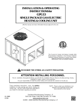
WIRING DIAGRAM
NOTES:
1. Couper le courant avant de faire letretien.
2. Employez uniquement des conducteurs en cuivre.
R6GN-150*/180* Series Convertible Package Gas Heat/Electric Air Conditioner
1. Disconnect all power before servicing.
2. For supply connections use copper conductors only.
3. If any of the original wire as supplied with the furnace must be replaced, it must
be replaced with wiring material having a temperature rating of at least 105C.
4. For supply wire ampacities and overcurrent protection, see unit rating label.
5. Remove white wire from POWER BLOCK- L3 and connect to autotransformer red wire.
6. For 120C Models only. For 208V operation remove wire from 230V tap and
place on 208V tap.
Three Phase 60 Hz.208-230/460 Volt
710849A
01/11
(Replaces 7108490)
Field Supplied Disconnect (3Phase Power Only)
For supply connections use copper conductors only.
Unit Terminal
Block
T2
T3
T1
IBC
Indoor Blower Motor
L1
L2
L3
GND
FUSE
BLOCK
1
2
3
BK WH
INDUCER
MOTOR
BOR
Transformer
See Note 6
Autotransformer
460V
Units Only
RED
See Note 5
L3 L2
RD/WH BK
LVT-C (24V COM.)
CC1
24V Hot
Max
Temp.
Limit
24V Common
Flame
Rollout
Switch
Upper
Secondary
Limit
IBC
OFC
2
3
1
2
3
1
CC2
CLOR1
(Field
Installed
Option)
Stage 1
Evap.
Freezestat
Low
Pressure
Switch
High
Pressure
Switch
CLOR2
(Field
Installed
Option)
E-5
E-4
LVT-Y1 (Stage 1 Cool)
LVT-Y2 (Stage 2 Cool)
E-2
E-1
LVT-W1 (Stage 1 Heat)
LVT-W2 (Stage 2 Heat)
E-8
E-15
E-14
BOR
95
96
LVT-G
LVT-R
E-9
To Mixed Air Sensor
(When Econ Used)
TDR - Time Delay Relay
IBC - Contactor, Indoor Blower Motor
CC1&2 - Contactor, Stage 1&2 Compressor
OFC - Contactor, Outdoor Fan
CCH - Crankcase Heaters, Stage 1&2 Compressor
LVT - Low Voltage Terminal
BR - Blower Relay
CLOR1 & 2 - Compressor Lockout Relay
BOR - Blower Overload Relay
TB - Terminal Board - HX
S
S
S
C
C
C
R
R
R
Compressor 2
T2
T1
T3
CC2
CC2
SC-4
SC-5
Compressor 1
T2
T1
T3
CC1
CC1
SC-4
SC-5
Outdoor
Fan Motor
Outdoor
Fan Motor
Outdoor
Fan Motor
BK
WH
C1-3
C1-1
C1-2
C2-3
C2-1
C2-2
C1-3
C1-1
C1-2
E-4
E-2
E-1
Stage 2
Evap.
Freezestat
Low
Pressure
Switch
High
Pressure
Switch
SC-1
SC-1
SC-2 SC-2
E-3
POWER BLOCK
P1-2
P1-8
P1-3
P2-3
K2
S1
S2
IGNITION
CONTROL
G
C
R
L
COM
NC
NO
BLOWER
TIME
DELAY
K1
P2-4
W1
W2
HV
TRANSFORMER
FS
P2-1
COM
P1-9
P1-6
TB-3
TB-2
GAS VALVE
PRESSURE
SWITCH
SPARK
IGNITOR
FLAME
SENSOR
IC-L1
IC-IND
IC-K4
GND
High Limit Input
Rollout Switch Input
C
230V
208V
95 96
- Indicates plug connection.
Letter Indicates which plug.
Number indicates pin location.
E - Economizer
SC - Safety Circuit
IC - Ignititon Control
Status Light
(Red)
Ignition Control Failure Code
Steady On
2 flashes
Operation Normal
3 flashes
4 flashes
5 flashes
6 flashes
7 flashes
8 flashes
9 flashes
10 flashes
Pressure/centrifugal switch open with inducer on
Lockout from too many failed ignition tries
Lockout from too many flame losses
High temperature switch open
Rollout switch open
Flame present with gas off`
Exceeded max limit trips in one call for heat (5)
Gas Valve Fault
Pressure/centrifugal switch closed with inducer off
4A
OPTIONAL
OPTIONAL