1
IMPORTANT:
Go to www.extron.com for the complete
user guide, installation instructions, and
ore connecting the
pr
wer source.
DTP T/R DP 330 and DTP T/R DP 230 • Setup Guide
This guide provides instructions for an experienced installer to install either the Extron
DTP T/R DP 330 or DTP T/R DP 230 Display Port Extenders and to make all connections.
Installation
For additional mounting details and considerations, see the DTP T/R DP 330 and DTP T/R 230 User Guide at www.extron.com).
Step 1 — Mounting
Turn off or disconnect all equipment power sources and mount the transmitter and receiver as required.
Step 2 — Input and Output Rear Panel Connections
OVER TP
RS-232
IR
Tx Rx Tx RxG
POWER
12V
0.8A MAX
SIG LINK
IN
OUTPUTS
AUDIO
AUDIO
INPUTS
OVER TP
RS-232
IR
Tx Rx Tx RxG
POWER
12V
0.8A MAX
SIG LINK
OUT
DTP
HDBT
DDAABBII EE CC
FF HHCC GGII
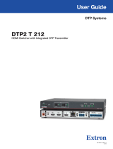
Figure 1. DTP T/R DP 330 and DTP T/R DP 230 Rear Panel Features
A
DisplayPort Input port — Connect a DisplayPort video input to this connector. The transmitters also accept
embedded digital audio on this port.
B
Audio Input port — Connect an audio input device to this 3.5 mm mini jack on the transmitter.
C
Over TP connector — To pass serial and infrared data or control signals on the Over TP RJ-45
TxRx
RxTx
Gnd
Gnd
RS-232 De
G
RS-232 IR
Rx
Tx
Tx
Rx
output, make the following connections via the RS-232 and IR captive screw connectors on the
transmitter and receiver.
Transmitter — Connect the controlling device.
Receiver — Connect the device to be controlled.
D
TP function switch —
If the receiving device is in the Extron DTP series, set this switch to DTP. The twisted
pair (TP) output consists of HDMI with embedded audio, analog audio, RS-232 and IR,
and remote power. The transmitter and receiver can be powered by one 12 VDC power
supply connected to either unit.
For an HDBaseT-enabled receiving device, set this switch to HDBT. The TP output consists of HDMI with embedded audio plus
RS-232 and IR. The transmitter and receiving device each requires its own 12 VDC power supply.
ATTENTION:
• Position this switch BEFORE connecting the appropriate device to the TP connector. Failure to comply can damage the
endpoint.
• Positionnez le sélecteur AVANT de connecter l’appareil approprié au connecteur TP. Ne pas respecter cette procédure
pourrait endommager le point de connexion.
E
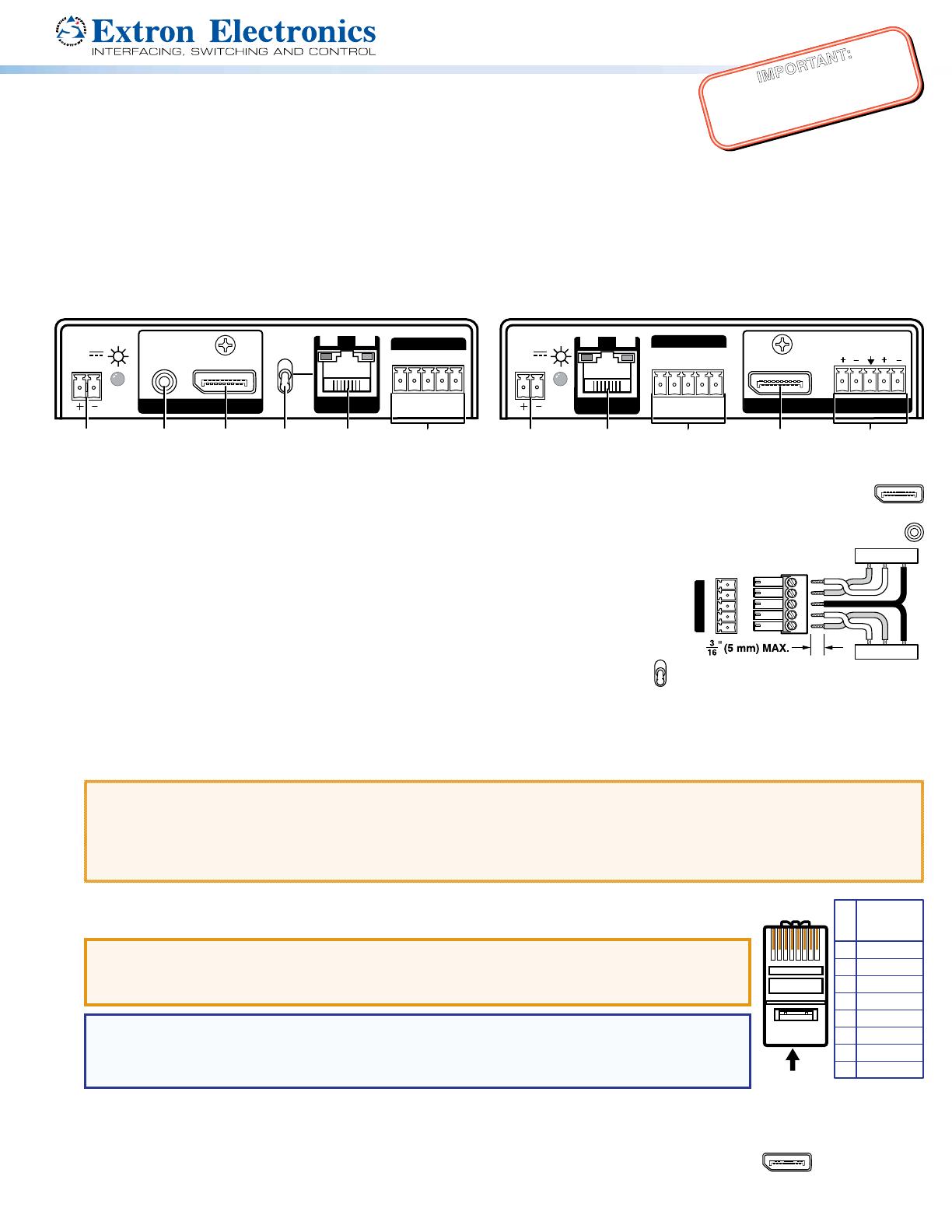
Out port and In port— Connect a shielded twisted pair (STP) cable between the Out (RJ-45) port on the
5
Pin
1
2
3
6
7
8
4
Wire color
White-green
Green
White-orange
White-blue
Orange
White-brown
Brown
Blue
TIA/EIA T
568B
12345678
transmitter and either the DTP In port or HDBT port on the receiving device.
ATTENTION:
• Do not connect this connector to a computer data or telecommunications network.
• Ne connectez pas ces port à des données informatiques ou à un réseau de télécommunications.
NOTE: Extron XTP DTP 24 shielded twisted pair (STP) cable is preferred for best results, but other
STP cable is acceptable. Extron recommends that you terminate both cable ends in accordance
with the following, at a minimum: TIA/EIA T 568B and 24 AWG, solid conductor, shielded cable with
400 MHz bandwidth.
Signal LED indicator — Lights when the device is transmitting or receiving a video signal.
Link LED indicator — Lights when a valid link between a DTP or HDBT input and output is established.
G
DisplayPort Output port — Connect a DisplayPort video display to this connector.
F