
Please read this manual carefully before operating
your TV. Retain it for future reference.
Record model number and serial number of the TV.
Refer to the label on the back cover and quote this
information to your dealer when requiring service.
LCD TV
OWNER’S MANUAL
LCD TV MODELS
32LF73
42LF73
32LH33
42LH33
Trade Mark of the DVB Digital Video
Broadcasting Project (1991 to 1996)
6504 : 32LF7300
6503 : 42LF7300
6506 : 32LH3300
6505 : 42LH3300
ENGLISH
Model :
Serial No. :
ID Number(s) :


GB-1
ACCESSORIES
Ensure that the following accessories are included with your TV. If an accessory is missing, please contact the dealer
where you purchased the TV.
Image shown may differ from your TV.
/WNERgS
-ANUAL
Owner's manual
A
V
M
O
D
E
E
N
E
R
G
Y
S
A
V
I
N
G
R
ET
U
RN
/ E
X
I
T
MEN
U
Q.MENU
INFO
GUIDE
i
M
U
T
E
PO
W
E
R
L
I
S
T
Q
.
V
I
E
W
MARK
F
A
V
A
V
M
O
D
E
E
N
E
R
G
Y
S
A
V
I
N
G
R
ET
U
RN
/ E
X
I
T
MEN
U
Q.MENU
INFO
GUIDE
i
M
U
T
E
PO
W
E
R
L
I
S
T
Q
.
V
I
E
W
MARK
F
A
V
Owner’s Manual Batteries Power Cord
A
V
M
O
D
E
E
N
E
R
G
Y
S
A
V
I
N
G
R
ET
U
R
N
/ E
X
I
T
MEN
U
Q.MENU
INFO
GUIDE
i
M
U
T
E
PO
W
E
R
L
I
S
T
Q
.
V
I
E
W
MARK
F
A
V
or
This item is not included for all models.
* Lightly wipe any stains or
ngerprints on the surface of the TV
with the polishing cloth.
Polishing Cloth
Polishing cloth for use on
the screen.
Do not use excessive force. This may
cause scratching or discolouration.
Remote Control
(Only 32/42LF73
**
) (Only 32LF73
**
, 32/42LH33
**
)
or
x 4
A
V
M
O
D
E
E
N
E
R
G
Y
S
A
V
I
N
G
R
ET
U
R
N
/ E
X
I
T
MEN
U
Q.MENU
INFO
GUIDE
i
M
U
T
E
PO
W
E
R
L
I
S
T
Q
.
V
I
E
W
MARK
F
A
V
x 4
Protection Cover
(Refer to p.12)
Bolts for stand assembly
(Refer to p.8)
1-screw for stand xing
(Refer to p.9)
RW230
(32LF73**, 32LH33**) (32/42LF73**, 32/42LH33**)
AW-47LG30M
Wall Mounting Bracket (Seperate purchase)
HDMI, the HDMI logo and High-Definition
Multimedia Interface are trademarks or registered
trademarks of HDMI Licensing LLC.
■
ACCESSORIES

GB-2
CONTENTS
CONTENTS
ACCESSORIES
PREPARATION
Front Panel Controls - - - - - - - - - - - - - - - - - - - - - - - - 4
Back Panel Information- - - - - - - - - - - - - - - - - - - - - - - 6
Stand Installation - - - - - - - - - - - - - - - - - - - - - - - - - - - 8
Desktop Pedestal Installation - - - - - - - - - - - - - - - - - - 9
Attaching the TV to a Desk
(Only 32LF73**, 32/42LH33**)
9
Careful installation advice - - - - - - - - - - - - - - - - - - - - 10
Back Cover for Wire Arrangement - - - - - - - - - - - - - - 11
Swivel Stand - - - - - - - - - - - - - - - - - - - - - - - - - - - - - 12
Not Using the Desk-Type Stand - - - - - - - - - - - - - - - 12
Wall Mount: Horizontal Installation - - - - - - - - - - - - - - 13
Antenna Connection- - - - - - - - - - - - - - - - - - - - - - - - 14
EXTERNAL EQUIPMENT SETUP
HD Receiver Setup - - - - - - - - - - - - - - - - - - - - - - - - 15
DVD Setup - - - - - - - - - - - - - - - - - - - - - - - - - - - - - - 17
VCR Setup - - - - - - - - - - - - - - - - - - - - - - - - - - - - - - 19
Insertion of CI Module - - - - - - - - - - - - - - - - - - - - - - 21
Digital Audio Out Setup - - - - - - - - - - - - - - - - - - - - - 21
Headphone Setup - - - - - - - - - - - - - - - - - - - - - - - - - 21
Other A/V Source Setup - - - - - - - - - - - - - - - - - - - - - 22
USB Setup (Only 32/42LF73**) - - - - - - - - - - - - - - - - 22
PC Setup - - - - - - - - - - - - - - - - - - - - - - - - - - - - - - - 23
WATCHING TV / PROGRAMME CONTROL
Remote Control Key Functions (Only 32/42LF73**)- - 30
Remote Control Key Functions (Only 32/42LH33**) - 32
Turning on the TV - - - - - - - - - - - - - - - - - - - - - - - - - 34
Programme Selection- - - - - - - - - - - - - - - - - - - - - - - 34
Volume Adjustment - - - - - - - - - - - - - - - - - - - - - - - - 34
Quick Menu- - - - - - - - - - - - - - - - - - - - - - - - - - - - - - 35
On Screen Menus Selection and Adjustment - - - - - - 36
Auto Programme Tuning - - - - - - - - - - - - - - - - - - - - 37
Manual Programme Tuning (In Digital Mode) - - - - - - 40
Manual Programme Tuning (In Analogue Mode) - - - - 42
Programme Edit- - - - - - - - - - - - - - - - - - - - - - - - - - - 44
5V Antenna Power (In Antenna Mode Only) - - - - - - - 46
Software Update (In Digital Cable Mode Only) - - - - - 47
Diagnostics - - - - - - - - - - - - - - - - - - - - - - - - - - - - - - 50
CI Information (In Digital Mode Only) - - - - - - - - - - - - 51
CI+CAM - - - - - - - - - - - - - - - - - - - - - - - - - - - - - - - - 52
Selecting the Programme List - - - - - - - - - - - - - - - - - 54
Input List - - - - - - - - - - - - - - - - - - - - - - - - - - - - - - - - 55
Input Label - - - - - - - - - - - - - - - - - - - - - - - - - - - - - - 56
AV Mode - - - - - - - - - - - - - - - - - - - - - - - - - - - - - - - - 56
Multifeed - - - - - - - - - - - - - - - - - - - - - - - - - - - - - - - - 57
Initializing (Reset to original factory settings) - - - - - - 58
TO USE A USB DEVICE (Only 32/42LF73**)
Photo List - - - - - - - - - - - - - - - - - - - - - - - - - - - - - - - 60
Music List - - - - - - - - - - - - - - - - - - - - - - - - - - - - - - - 64

GB-3
CONTENTS
TV GUIDE (EPG; ELECTRONIC PRO-
GRAMME GUIDE) (In Digital Mode)
PICTURE CONTROL
Picture Size (Aspect Ratio) Control - - - - - - - - - - - - - 71
Energy Saving - - - - - - - - - - - - - - - - - - - - - - - - - - - - 73
Preset Picture Settings - - - - - - - - - - - - - - - - - - - - - - 74
Manual Picture Adjustment - - - - - - - - - - - - - - - - - - - 75
Picture Improvement Technology- - - - - - - - - - - - - - - 76
Picture Reset- - - - - - - - - - - - - - - - - - - - - - - - - - - - - 78
Demo Mode (Only 32/42LF73**) - - - - - - - - - - - - - - - 79
Mode Setting - - - - - - - - - - - - - - - - - - - - - - - - - - - - - 80
SOUND & LANGUAGE CONTROL
Auto Volume Leveler - - - - - - - - - - - - - - - - - - - - - - - 81
Preset Sound Settings - Sound Mode - - - - - - - - - - - 82
Sound Setting Adjustment - User Mode - - - - - - - - - - 83
SRS Trusurround XT - - - - - - - - - - - - - - - - - - - - - - - 83
Balance- - - - - - - - - - - - - - - - - - - - - - - - - - - - - - - - - 84
TV Speakers On/Off Setup - - - - - - - - - - - - - - - - - - - 85
Selecting Digital Audio Out - - - - - - - - - - - - - - - - - - - 86
Audio Reset- - - - - - - - - - - - - - - - - - - - - - - - - - - - - - 87
I/II- - - - - - - - - - - - - - - - - - - - - - - - - - - - - - - - - - - - - 88
Language Selection - - - - - - - - - - - - - - - - - - - - - - - 90
TIME SETTING
Clock Setup- - - - - - - - - - - - - - - - - - - - - - - - - - - - - - 91
Auto On/Off Time Setting - - - - - - - - - - - - - - - - - - - - 92
Auto Shut-Off Setting - - - - - - - - - - - - - - - - - - - - - - - 93
Sleep Timer Setting - - - - - - - - - - - - - - - - - - - - - - - - 93
PARENTAL CONTROL / RATINGS
Set Password & Lock System - - - - - - - - - - - - - - - - - 94
Block Programme - - - - - - - - - - - - - - - - - - - - - - - - - 95
Parental Control (In Digital Mode Only) - - - - - - - - - - 96
Key Lock- - - - - - - - - - - - - - - - - - - - - - - - - - - - - - - - 97
TELETEXT
Switch On/Off - - - - - - - - - - - - - - - - - - - - - - - - - - - - 98
Simple Text - - - - - - - - - - - - - - - - - - - - - - - - - - - - - - 98
Fastext - - - - - - - - - - - - - - - - - - - - - - - - - - - - - - - - - 98
Special Teletext Functions - - - - - - - - - - - - - - - - - - - 99
APPENDIX
Troubleshooting - - - - - - - - - - - - - - - - - - - - - - - - - - 100
Maintenance - - - - - - - - - - - - - - - - - - - - - - - - - - - - 101
Product Specications - - - - - - - - - - - - - - - - - - - - - 102
OPEN SOURCE LICENSE - - - - - - - - - - - - - - - - - - 103
NOTICE
This product incorporates copy protection technology that is protected by U.S. and foreign patents, including patent
numbers 5,315,448 and 6,836,549, and other intellectual property rights. The use of Macrovision’s copy protection
technology in the product must be authorized by Macrovision. Reverse engineering or disassembly is prohibited.
►

GB-4
PREPERATION
FRONT PANEL CONTROLS
Image shown may differ from your TV.
32/42LF73
**
CAUTION
When the TV cannot be turned on with the remote control, press the main power button on the TV.
(When the power is turned off with the main power button on the TV, it will not be turned on with the remote
control).
►
PREPARATION
Intelligent sensor
Adjusts picture according to the
surrounding conditions.
PROGRAMME
VOLUME
OK
MENU
INPUT
Power/Standby Indicator
• illuminates red in standby mode.
• illuminates blue when the TV is switched on.
Remote Control Sensor
MAIN POWER

GB-5
PREPERATION
32/42LH33
**
CAUTION
When the TV cannot be turned on with the remote control, turn on the main power switch on the TV.
(When the main power switch is off, the TV will not be turned on with the remote control.)
►
INPUT
MENU
OK
P
INPUT
MENU
OK
P
PROGRAMME
VOLUME
OK
MENU
INPUT
INPUT
MENU
OK
P
Power/Standby Indicator
• illuminates red in standby mode.
• illuminates blue when the TV is switched on.
Remote Control Sensor
INPUT
MENU
OK
P
Main Power Switch (Power On/Off)
POWER
(Standby/Operation)

GB-6
PREPERATION
PREPARATION
BACK PANEL INFORMATION
Image shown may differ from your TV.
32/42LF73
**
ANTENNA IN
(RGB)
AV IN 3
L/MONO
R
AUDIO
VIDEO
H/P
2
3
1(DVI)
Power Cord Socket
This TV operates on an AC power. The voltage is
indicated on the Specications page. Never attempt to
operate the TV on DC power.
RGB/DVI Audio Input
Connect the audio from a PC or DTV.
OPTICAL DIGITAL AUDIO OUT
Connect digital audio to various types of equipment.
Connect to a Digital Audio Component.
Use an Optical audio cable.
Euro Scart Socket (AV1 / AV2)
Connect scart socket input or output from an external
device to these jacks.
HDMI/DVI IN Input
Connect an HDMI signal to HDMI IN. Or DVI
(VIDEO) signal to HDMI/DVI port with DVI to HDMI cable.
RGB IN Input
Connect the output from a PC.
Component Input
Connect a component video/audio device to these jacks.
Antenna Input
Connect antenna or cable to this jack.
USB Input
Connect USB storage device to this jack.
PCMCIA (Personal Computer Memory Card
International Association) Card Slot
Insert the CI Module to PCMCIA CARD SLOT.
(This feature is not available in all countries.)
Audio/Video Input
Connect audio/video output from an external device to
these jacks.
Headphone Socket
Plug the headphone into the headphone socket.
■

GB-7
PREPERATION
32/42LH33
**
2
1
ANTENNA IN
(RGB)
AV IN 3
L/MONO
R
AUDIO
VIDEO
H/P
Power Cord Socket
This TV operates on an AC power. The voltage is
indicated on the Specications page. Never attempt to
operate the TV on DC power.
RGB/DVI Audio Input
Connect the audio from a PC or DTV.
OPTICAL DIGITAL AUDIO OUT
Connect digital audio to various types of equipment.
Connect to a Digital Audio Component.
Use an Optical audio cable.
Euro Scart Socket (AV1 / AV2)
Connect scart socket input or output from an external
device to these jacks.
HDMI/DVI IN Input
Connect an HDMI signal to HDMI IN. Or DVI
(VIDEO) signal to HDMI/DVI port with DVI to HDMI cable.
RGB IN Input
Connect the output from a PC.
Component Input
Connect a component video/audio device to these jacks.
Antenna Input
Connect antenna or cable to this jack.
SERVICE ONLY PORT
PCMCIA (Personal Computer Memory Card
International Association) Card Slot
Insert the CI Module to PCMCIA CARD SLOT.
(This feature is not available in all countries.)
Audio/Video Input
Connect audio/video output from an external device to
these jacks.
Headphone Socket
Plug the headphone into the headphone socket.

GB-8
PREPERATION
PREPARATION
STAND INSTALLATION
Image shown may differ from your TV.
When assembling the desk type stand, check whether the bolt is fully tightened. (If not tightened fully, the product can tilt
forward after the product installation.) If you tighten the bolt with excessive force, the bolt can deviate from abrasion of the
tightening part of the bolt.
Only 32/42LF73** Only 32/42LH33**
➊
Carefully place the TV screen side down on a
cushioned surface to protect the screen from damage.
➊
Carefully place the TV screen side down on a
cushioned surface to protect the screen from damage.
➋
Assemble the parts of the Stand Body with the
Stand Base of the TV.
➋
Assemble the TV as shown.
A
V
M
O
D
E
E
N
E
R
G
Y
S
A
V
I
N
G
R
ET
U
R
N
/ E
X
I
T
MEN
U
Q.MENU
INFO
GUIDE
i
M
U
T
E
PO
W
E
R
L
I
S
T
Q
.
V
I
E
W
MARK
F
A
V
Stand Body
Stand Base
➌
Assemble the TV as shown.
➌
Fix the 4 bolts securely using the holes in the back of
the TV.
➍
Fix the 4 bolts securely using the holes in the
back of the TV.
Front
When assembling the stand, make sure to
distinguish and assemble the front and rear side
of the stand correctly.
■

GB-9
PREPERATION
DESKTOP PEDESTAL INSTALLATION
For adequate ventilation allow a clearance of 4” (10cm) all around the TV.
P R
VO L
O K
M E N U
IN P U T
/I
4 inches
4 inches4 inches
4 inches
ATTACHING THE TV TO A DESK (ONLY 32LF73
**
, 32/42LH33
**
)
The TV must be attached to desk so it cannot be pulled in a forward/backward direction, potentially causing injury or
damaging the product. Use only an attached screw.
1-Screw
(provided as parts of the product)
Stand
Desk
WARNING
To prevent TV from falling over, the TV should be securely attached to the floor/wall per installation instructions.
Tipping, shaking, or rocking the machine may cause injury.
►

GB-10
PREPERATION
PREPARATION
CAREFUL INSTALLATION ADVICE
You should purchase necessary components to fix the TV safety and secure to the wall on the market.
Position the TV close to the wall to avoid the possibility of it falling when pushed.
The instructions shown below are a safer way to set up the TV, by fixing it to the wall, avoiding the possibility of it falling
forwards if pulled. This will prevent the TV from falling forward and causing injury. This will also prevent the TV from
damage. Ensure that children do not climb or hang from the TV.
2
1
➊
Use the eye-bolts or TV brackets/bolts to fix the product to the wall as shown in the picture.
(If your TV has bolts in the eyebolts, loosen these bolts.)
* Insert the eye-bolts or TV brackets/bolts and tighten them securely in the upper holes.
➋
Secure the wall brackets with the bolts on the wall. Match the height of the bracket that is mounted on the wall.
3
➌
Use a sturdy rope to tie the product for alignment. It is safer to tie the rope so it becomes horizontal between the
wall and the product.
NOTE
When moving the TV undo the cords first.
Use a platform or cabinet strong and large enough to support the size and weight of the TV.
To use the TV safely make sure that the height of the bracket on the wall and on the TV is the same.
■
■
■
►
►
►

GB-11
PREPERATION
BACK COVER FOR WIRE ARRANGEMENT
Image shown may differ from your TV.
➊
Connect the cables as necessary.
To connect additional equipment, see the External Equipment Setup section.
➋
Install the CABLE MANAGEMENT CLIP as shown.
CABLE MANAGEMENT CLIP
➌
Fit the CABLE MANAGEMENT CLIP as shown.
NOTE
Do not use the CABLE MANAGEMENT CLIP to lift the TV.
- If the TV is dropped, you may be injured or the TV may be damaged.
■
►

GB-12
PREPERATION
PREPARATION
SWIVEL STAND
Image shown may differ from your TV.
After installing the TV, you can adjust the TV manually to the left or
right direction by 20 degrees to suit your viewing position.
NOT USING THE DESKTYPE STAND
Image shown may differ from your TV.
When installing the wall-mounted unit, use the protection cover.
or
or
Insert the PROTECTION COVER into the TV until clicking sound.
■
■

GB-13
PREPERATION
The TV can be installed in various ways such as on a wall, or on a desktop etc.
The TV is designed to be mounted horizontally.
EARTHING
Ensure that you connect the earth wire to prevent
possible electric shock. If grounding methods are not
possible, have a qualified electrician install a separate
circuit breaker.
Do not try to earth the TV by connecting it to telephone
wires, lightening rods or gas pipes.
Power Supply
Circuit breaker
WALL MOUNT: HORIZONTAL INSTALLATION
We recommend the use of a LG Brand wall mounting bracket when mounting the TV to a wall.
We recommend that you purchase a wall mounting bracket which supports VESA standard.
LG recommends that wall mounting be performed by a qualified professional installer.
NOTE
Should Install wall mount on a solid wall perpendicular to the floor.
Should use a special wall mount, if you want to install it to ceiling or slanted wall.
The surface that wall mount is to be mounted on should be of sufficient strength to support the weight of TV set; e.g.
concrete, natural rock, brick and hollow block.
Installing screw type and length depends on the wall mount used. Further information, refer to the instructions
included with the mount.
LG is not liable for any accidents or damage to property or TV due to incorrect installation:
- Where a non-compliant VESA wall mount is used.
- Incorrect fastening of screws to surface which may cause TV to fall and cause personal injury.
- Not following the recommended Installation method.
AA
BB
4 inches
4 inches
4 inches
4 inches
4 inches
AA
BB
Model
VESA
(A * B)
Standard
Screw
Quantity
32LF73
**
, 32LH33
**
200
*
100 M4 4
42LF73
**
, 42LH33
**
200
*
200 M6 4
■
■
■
■
■
►
►
►
►
►

GB-14
PREPERATION
PREPARATION
To prevent damage do not connect to the mains outlet until all connections are made between the devices.
ANTENNA CONNECTION
For optimum picture quality, adjust antenna direction.
An antenna cable and converter are not supplied.
ANTENNA IN
(RGB)
AV IN 3
L/ MONO
R
AUDIO
VIDEO
H/P
2
3
1(DVI)
Wall
Antenna
Socket
Outdoor
Antenna
(VHF, UHF)
Multi-family Dwellings/Apartments
(Connect to wall antenna socket)
Single-family Dwellings /Houses
(Connect to wall jack for outdoor antenna)
RF Coaxial Wire (75 ohm)
ANTENNA IN
(RGB)
AV IN 3
L/ MONO
R
AUDIO
VIDEO
H/P
2
3
1(DVI)
UHF
VHF
Signal
Amplifier
Terrestrial
Antenna
In poor signal areas, to achieve better picture quality it may be necessary to install a signal amplifier to the antenna as
shown above.
If signal needs to be split for two TVs, use an antenna signal splitter for connection.
■
■
■
■
■

GB-15
EXTERNAL EQUIPMENT SETUP
To avoid damaging any equipment, never plug in any power cord until you have finished connecting all equipment.
This section on EXTERNAL EQUIPMENT SETUP mainly uses diagrams for 32LF73
**
model.
Image shown may differ from your TV.
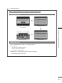
HD RECEIVER SETUP
This TV can receive Digital RF/Cable signals without an external digital set-top box. However, if you do receive Digital
signals from a digital set-top box or other digital external device, refer to the diagram as shown below.
Connecting with a Component Cable
➊
Connect the video outputs (Y, PB, PR) of the digital set top box to the
COMPONENT IN VIDEO jacks on the TV.
➋
Connect the audio outputs of the digital set-top box to the
COMPONENT IN AUDIO jacks on the TV.
➌
Turn on the digital set-top box. (Refer to the owner’s manual for the
digital set-top box.)
➍
Select Component input source using the INPUT button on the
remote control.
Signal Component HDMI
480i/576i O X
480p/576p O O
720p/1080i O O
1080p
O
(50/60Hz only)
O
(24Hz/30Hz/50Hz/60Hz)
■
■
■
■
EXTERNAL EQUIPMENT SETUP
ANTENNA IN
(RGB)
2
3
1(DVI)
ANTENNA IN
(RGB)
2
3
1(DVI)
ANTENNA IN
(RGB)
2
3
1(DVI)
➊
➋

GB-16
EXTERNAL EQUIPMENT SETUP
EXTERNAL EQUIPMENT SETUP
Connecting with an HDMI Cable
➊
Connect the digital set-top box to HDMI/DVI IN 1, HDMI IN 2, HDMI IN 3 or HDMI
IN 4 (Only 32/42LF73
**
) jack on the TV.
➋
Turn on the digital set-top box.
(Refer to the owner’s manual for the digital set-top box.)
➌
Select HDMI1, HDMI2, HDMI3 or HDMI4 (Only 32/42LF73
**
) input source using the
INPUT button on the remote control.
NOTE
Check that your HDMI cable is version 1.3 or higher. If the HDMI cables don’t support
HDMI version 1.3, flickering or no screen display can result. Please use the latest
cables that support at least HDMI version 1.3.
Connecting with an HDMI to DVI Cable
➊
Connect the digital set-top box to HDMI/DVI IN 1 jack on the TV.
➋
Connect the audio output of the digital set-top box to the AUDIO IN (RGB/DVI)
jack on the TV.
➌
Turn on the digital set-top box.
(Refer to the owner’s manual for the digital set-top box.)
➍
Select HDMI 1 input source using the INPUT button on the remote control.
►
ANTENNA IN
(RGB)
2
3
1(DVI)
ANTENNA IN
(RGB)
2
3
1(DVI)
ANTENNA IN
(RGB)
2
3
1(DVI)
➊
ANTENNA IN
(RGB)
2
3
1(DVI)
ANTENNA IN
(RGB)
2
3
1(DVI)
ANTENNA IN
(RGB)
2
3
1(DVI)
➊
➋

GB-17
EXTERNAL EQUIPMENT SETUP
DVD SETUP
Connecting with a Component Cable
➊
Connect the video outputs (Y, PB, PR) of the DVD to the
COMPONENT IN VIDEO jacks on the TV.
➋
Connect the audio outputs of the DVD to the COMPONENT IN
AUDIO jacks on the TV.
➌
Turn on the DVD player, insert a DVD.
➍
Select Component input source using the INPUT button on the
remote control.
➎
Refer to the DVD player’s manual for operating instructions.
Component Input ports
To achieve better picture quality, connect a DVD player to the component input ports as shown below.
Component ports on the TV
Y PB PR
Video output ports on DVD player
Y
Y
Y
Y
PB
B-Y
Cb
Pb
PR
R-Y
Cr
Pr
ANTENNA IN
(RGB)
2
3
1(DVI)
(R) AUDIO (L)
AUDIO/
VIDEO
ANTENNA IN
(RGB)
2
3
1(DVI)
ANTENNA IN
(RGB)
2
3
1(DVI)
➊
➋

GB-18
EXTERNAL EQUIPMENT SETUP
EXTERNAL EQUIPMENT SETUP
Connecting with a Euro Scart Cable
➊
Connect the Euro scart socket of the DVD to the AV1 Euro scart socket on the
TV.
➋
Turn on the DVD player, insert a DVD.
➌
Select AV1 input source using the INPUT button on the remote control.
If connected to AV2 Euro scart socket, select AV2 input source.
➍
Refer to the DVD player’s manual for operating instructions.
NOTE
Any Euro scart cable used must be signal shielded.
Copy-protected programmes will not be output on the EURO scart sockets for
legal reasons. Even if it was output, the video signals fed through the EURO
scart sockets will be not recorded by copyright protection systems.
Scart Output
Main Input AV1 (SCART1 Output) AV2 (SCART2 Output)
Digital TV Mute Digital TV
Analogue TV
Mute
(Analogue TV if the TV mode you last
watched is Analogue mode.)
Analogue TV
AV1 (SCART1)
CVBS
AV1 (CVBS)
RGB
AV2 (SCART2) CVBS AV2 (CVBS)
Component Mute
RGB Mute
AV3(CVBS) AV3 (CVBS)
HDMI1
Mute
HDMI2 Mute
HDMI3 Mute
HDMI4 (Only 32/42LF73**) Mute
Connecting the HDMI Cable
➊
Connect the HDMI output of the DVD to the HDMI/DVI IN 1, HDMI IN 2,
HDMI IN 3 or HDMI IN 4 (Only 32/42LF73
**
) jack on the TV.
➋
Select HDMI1, HDMI2, HDMI3 or HDMI4 (Only 32/42LF73
**
) input source
using the INPUT button on the remote control.
➌
Refer to the DVD player’s manual for operating instructions.
NOTE
The TV can receive video and audio signals simultaneously when using a
HDMI cable.
If the DVD does not support Auto HDMI, you must set the output resolution
appropriately.
Check that your HDMI cable is version 1.3 or higher. If the HDMI cables don’t
support HDMI version 1.3, flickering or no screen display can result. Please
use the latest cables that support at least HDMI version 1.3.
►
►
►
►
►
ANTENNA IN
(RGB)
2
3
1(DVI)
(R) AUDIO (L)
AUDIO/
VIDEO
ANTENNA IN
(RGB)
2
3
1(DVI)
ANTENNA IN
(RGB)
2
3
1(DVI)
➊
ANTENNA IN
(RGB)
2
3
1(DVI)
(R) AUDIO (L)
AUDIO/
VIDEO
ANTENNA IN
(RGB)
2
3
1(DVI)
ANTENNA IN
(RGB)
2
3
1(DVI)
➊
Page is loading ...
Page is loading ...
Page is loading ...
Page is loading ...
Page is loading ...
Page is loading ...
Page is loading ...
Page is loading ...
Page is loading ...
Page is loading ...
Page is loading ...
Page is loading ...
Page is loading ...
Page is loading ...
Page is loading ...
Page is loading ...
Page is loading ...
Page is loading ...
Page is loading ...
Page is loading ...
Page is loading ...
Page is loading ...
Page is loading ...
Page is loading ...
Page is loading ...
Page is loading ...
Page is loading ...
Page is loading ...
Page is loading ...
Page is loading ...
Page is loading ...
Page is loading ...
Page is loading ...
Page is loading ...
Page is loading ...
Page is loading ...
Page is loading ...
Page is loading ...
Page is loading ...
Page is loading ...
Page is loading ...
Page is loading ...
Page is loading ...
Page is loading ...
Page is loading ...
Page is loading ...
Page is loading ...
Page is loading ...
Page is loading ...
Page is loading ...
Page is loading ...
Page is loading ...
Page is loading ...
Page is loading ...
Page is loading ...
Page is loading ...
Page is loading ...
Page is loading ...
Page is loading ...
Page is loading ...
Page is loading ...
Page is loading ...
Page is loading ...
Page is loading ...
Page is loading ...
Page is loading ...
Page is loading ...
Page is loading ...
Page is loading ...
Page is loading ...
Page is loading ...
Page is loading ...
Page is loading ...
Page is loading ...
Page is loading ...
Page is loading ...
Page is loading ...
Page is loading ...
Page is loading ...
Page is loading ...
Page is loading ...
Page is loading ...
Page is loading ...
Page is loading ...
Page is loading ...
Page is loading ...
Page is loading ...
Page is loading ...
Page is loading ...
Page is loading ...
Page is loading ...
Page is loading ...
Page is loading ...
Page is loading ...
Page is loading ...
Page is loading ...
-
 1
1
-
 2
2
-
 3
3
-
 4
4
-
 5
5
-
 6
6
-
 7
7
-
 8
8
-
 9
9
-
 10
10
-
 11
11
-
 12
12
-
 13
13
-
 14
14
-
 15
15
-
 16
16
-
 17
17
-
 18
18
-
 19
19
-
 20
20
-
 21
21
-
 22
22
-
 23
23
-
 24
24
-
 25
25
-
 26
26
-
 27
27
-
 28
28
-
 29
29
-
 30
30
-
 31
31
-
 32
32
-
 33
33
-
 34
34
-
 35
35
-
 36
36
-
 37
37
-
 38
38
-
 39
39
-
 40
40
-
 41
41
-
 42
42
-
 43
43
-
 44
44
-
 45
45
-
 46
46
-
 47
47
-
 48
48
-
 49
49
-
 50
50
-
 51
51
-
 52
52
-
 53
53
-
 54
54
-
 55
55
-
 56
56
-
 57
57
-
 58
58
-
 59
59
-
 60
60
-
 61
61
-
 62
62
-
 63
63
-
 64
64
-
 65
65
-
 66
66
-
 67
67
-
 68
68
-
 69
69
-
 70
70
-
 71
71
-
 72
72
-
 73
73
-
 74
74
-
 75
75
-
 76
76
-
 77
77
-
 78
78
-
 79
79
-
 80
80
-
 81
81
-
 82
82
-
 83
83
-
 84
84
-
 85
85
-
 86
86
-
 87
87
-
 88
88
-
 89
89
-
 90
90
-
 91
91
-
 92
92
-
 93
93
-
 94
94
-
 95
95
-
 96
96
-
 97
97
-
 98
98
-
 99
99
-
 100
100
-
 101
101
-
 102
102
-
 103
103
-
 104
104
-
 105
105
-
 106
106
-
 107
107
-
 108
108
-
 109
109
-
 110
110
-
 111
111
-
 112
112
-
 113
113
-
 114
114
-
 115
115
-
 116
116


