2
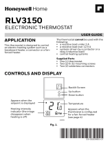
UWP Mounting System installation
Use 3x supplied
screws (#8 11/2
for red anchors and
#6 11/2 for yellow
anchors)
1. Before starting, turn the power off
at the breaker box or switch. Open
package to find the UWP. See Figure 1.
2. Position the UWP on wall. Level and
mark hole positions. See Figure 2.
Drill holes at marked positions, and
then lightly tap supplied wall anchors
into the wall using a hammer.
‒ If your box contains red anchors,
drill 7/32” holes.
‒ If your box contains yellow anchors,
drill 3/16” holes.
3. Pull the door open and insert the wires
through wiring hole of the UWP. See
Figure 3.
4. Place the UWP over the wall anchors.
Insert and tighten mounting screws
supplied with the UWP. Do not
overtighten. Tighten until the UWP
no longer moves. Close the door. See
Figure 4.
4
3
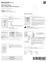
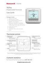
For the rectangular cover plate:
1. Mount the Cover Plate on the wall using
any of the 6 screw holes. Insert and tighten
the mounting screws supplied with the
Cover Plate. Do not overtighten. See Figure
1. Make sure the Cover Plate is level. Attach
the UWP by hanging it on the top hook
of the Cover Plate and then snapping the
bottom of the UWP in place. See Figure 2.
2. If there are no existing wall anchors:
a. Position the Cover Plate on wall. Level
and mark hole positions. See Figure 1.
b. Drill holes at marked positions, and then
lightly tap supplied wall anchors into the
wall using a hammer.
• If your box contains red anchors, drill
7/32” (5.6 mm) holes.
• If your box contains yellow anchors,
drill 3/16” (4.8 mm) holes.
• Use 2x supplied screws (#8 11/2”
(38 mm) for red anchors and #6
11/2” (38 mm) for yellow anchors).
2