
UM_Virgo_v1.8_121520
Virgo
Server Motherboard
User's Manual

Content
Preface ������������������������������������������������������������������������������������������������ i
Safety Instructions ������������������������������������������������������������������������������ ii
About This Manual ����������������������������������������������������������������������������� iii
Chapter 1� Product Features �������������������������������������������������������������� 1
1�1 Components ��������������������������������������������������������������������������������������1
1�2 Specifications �����������������������������������������������������������������������������������2
1�3 Feature ���������������������������������������������������������������������������������������������� 3
Chapter 2� Hardware Setup ���������������������������������������������������������������� 4
2�1 Central Processing Unit Setup ���������������������������������������������������������� 4
2.1.1 Processor Installation ..........................................................................................4
2�2 System Memory ��������������������������������������������������������������������������������7
2.2.1 DIMM Population .................................................................................................8
2.2.2 DCPMM DIMM Population ................................................................................10
2.2.3 Memory Installation ...........................................................................................11
Chapter 3� Motherboard Settings ����������������������������������������������������� 12
3�1 Block Diagram ���������������������������������������������������������������������������������12
3�2 Content List �������������������������������������������������������������������������������������13
3�3 Placement ���������������������������������������������������������������������������������������14
3�4 Connector and Jumper ��������������������������������������������������������������������15
3.4.1 Connector ...........................................................................................................15
3.4.2 Jumper ................................................................................................................20
3�5 System LED Indicator ����������������������������������������������������������������������21
3.5.1 Internal LED ........................................................................................................21
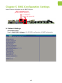
Chapter 4� BIOS Configuration Settings ������������������������������������������� 22
4�1 Navigation Keys �������������������������������������������������������������������������������22
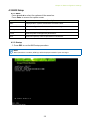
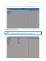
4�2 BIOS Setup ��������������������������������������������������������������������������������������23
4.2.1 Menu ...................................................................................................................23
4.2.2 Startup ................................................................................................................23
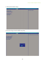
4.2.3 Update .................................................................................................................26
4.2.4 DCPMM Setup ....................................................................................................27
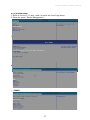
4�3 Main �����������������������������������������������������������������������������������������������29
4.3.1 Main ....................................................................................................................29
4�4 Advanced ����������������������������������������������������������������������������������������30
4.4.1 Peripheral Configuration .................................................................................... 30
4.4.2 Video Configuration ...........................................................................................30
4.4.3 OEMBoard Function ...........................................................................................30
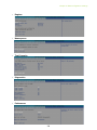
4.4.4 SIO AST2500 ......................................................................................................31
4.4.5 Socket Configuration .........................................................................................31
4.4.6 ME Configuration ...............................................................................................37
4.4.7 PCH Configuration .............................................................................................38
4.4.8 H2O IPMI Configuration .....................................................................................39
4.4.9 APEI Configuration .............................................................................................39
4.4.10 Console Redirection .........................................................................................39
4.4.11 H2O Event Log Config Manager ......................................................................40
4.4.12 H2oUve Configuration .....................................................................................40
4�5 Security �������������������������������������������������������������������������������������������41
Table of Contents

4.5.1 Security ...............................................................................................................41
4�6 Power ����������������������������������������������������������������������������������������������42
4.6.1 Power ..................................................................................................................42
4�7 Boot ������������������������������������������������������������������������������������������������43
4.7.1 Boot .....................................................................................................................43
4�8 Exit ��������������������������������������������������������������������������������������������������44
4.8.1 Exit.......................................................................................................................44
Chapter 5� BMC Configuration Settings ������������������������������������������� 45
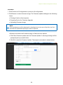
5�1 Network Settings �����������������������������������������������������������������������������45
5�2 Web GUI ������������������������������������������������������������������������������������������48
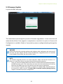
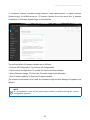
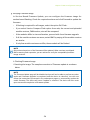
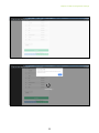
5�3 Firmware Update �����������������������������������������������������������������������������51
Chapter 6� Technical Support ����������������������������������������������������������� 56
Content

Copyright © 2017 AIC, Inc. All Rights Reserved.
This document contains proprietary information about
AIC® products and is not to be disclosed or used except in
accordance with applicable agreements.

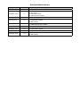
Document Release History
Release Date
Version Update Content
March, 2017 1 User's Manual release to public.
September, 2018 1.1
1. BIOS update
2. New Cover
3. Gramnatical Error
4. Connector and Jumper
October, 2018 1.2 Specification update
January, 2019 1.3
1. HW update
2. Specification update
3. BMC update
August, 2019 1.4
1. BIOS update
2. DIMM Configuration update
September, 2019 1.5 Jumper update
November, 2019 1.6
1.BIOS update
2. Specification update
December, 2019 1.7 SW update
September, 2020 1.8
1. New cover
2. BMC update

Copyright
No part of this publication may be reproduced, stored in a retrieval system, or
transmitted in any form or by any means, electronic, mechanical, photo-static, recording
or otherwise, without the prior written consent of the manufacturer.
Trademarks
All products and trade names used in this document are trademarks or registered
trademarks of their respective holders.
Changes
The material in this document is for information purposes only and is subject to change
without notice.
Warning
1. A shielded-type power cord is required in order to meet FCC emission limits and also
to prevent interference to the nearby radio and television reception. It is essential
that only the supplied power cord be used.
2. Use only shielded cables to connect I/O devices to this equipment.
3. You are cautioned that changes or modifications not expressly approved by the
party responsible for compliance could void your authority to operate the equipment.
Disclaimer
AIC® shall not be liable for technical or editorial errors or omissions contained herein.
The information provided is provided "as is" without warranty of any kind. To the extent
permitted by law, neither AIC or its aliates, subcontractors or suppliers will be liable
for incidental, special or consequential damages including downtime cost; lost prots;
damages relating to the procurement of substitute products or services; or damages
for loss of data, or software restoration. The information in this document is subject to
change without notice.
Instruction Symbols
Special attention should be given to the instruction symbols below.
NOTE
This symbol indicates that there is an explanatory or
supplementary instruction.
CAUTION
This symbol denotes possible hardware impairment. Upmost
precaution must be taken to prevent serious harware damage.
WARNING
This symbol serves as a warning alert for potential body
injury. The user may suffer possible injury from disregard or
lack of attention.
Preface

When installing, operating, or performing maintenance on this equipment, the following
safety precautions should always be observed in order to reduce the risk of fire, electric
shock, and personal injury.
Read and understand all instructions.
• Observe warnings and instructions marked on the product.
• For proper mounting instructions, please consult the User’s Manual provided with this
product.
• Do NOT place this product on an unstable cart, stand, table or uneven surface that
might cause the product to fall and sustain serious damage.
• Only install the equipment identified in the User’s Manual. Use of other equipment
could cause improper connection of circuitry and may result in fire or personal injury.
• This product should only be operated with the type of power source indicated on the
marked label. If you are uncertain about which type of power supply is used in your
area, consult your dealer or local Power Company.
• Disconnect the power supply module before removing power from the system. Unplug
this product from the wall outlet before cleaning. Use a damp cloth for cleaning. Do
not use liquid cleaners or aerosol cleaners.
• Do not use this product near a water source, such as a faucet.
• Never spill liquids of any kind on this product.
• Never shove objects of any kind into this product’s open slots, as they may touch
dangerous voltage points or short out parts and could result in fire or electric shock.
• Do not block or cover slots and openings in this unit, as they were made for ventilation
and prevent this unit from overheating. Do not place this product in a built-in
installation unless proper ventilation is available.
• Do not disassemble this product. This product should only be taken apart by trained
personnel. Opening or removing covers and circuit boards may expose you to electric
shock or other risks. Incorrect reassembly can also cause electric shock when the
unit is subsequently used.
• Risk of explosion is possible if battery is replaced with an incompatible type. Dispose
of used batteries accordingly.
• This product is equipped with a three-wire grounding type plug, a plug with a third
(grounding) pin. As a safety feature, this plug is intended to fit only into a grounding
type power outlet. If you are unable to insert the plug into the outlet, contact your
electrician to replace the outlet. Do not remove the grounding type plug or use a
3-Prong To 2-Prong Adapter to circumvent the safety feature; doing so may result in
electric shock and/or damage to this product.
Safety Instructions

Thank you for selecting and purchasing the Virgo Serverboard.
This user's manual is provided for professional technicians to perform easy hardware
setup, basic system configurations, and quick software startup. This document pellucidly
presents a brief overview of the product design, device installation, and firmware settings
for the Virgo motherboard. For the latest version of this user's manual, please refer to the
AIC® website: https://www.aicipc.com/tw/productdetail/20861.
Chapter 1 Product Features
This chapter delivers the overall layout of the product, including the fundamental
components on the motherboard, design specifications, and noteworthy features. Virgo is
an ideal server grade motherboard that is specifically designed to accommodate diverse
enterprises for managing heavy workloads, databases, nearline applications, and cloud
deployments. This product supports the Intel® Xeon® Scalable Processors and Socket P0
(LGA-3647) with a memory support 12 DDR4 2400/2666 MHz DIMM accross 6 channels
per CPU.
Chapter 2 Hardware Setup
This chapter displays an easy installation guide for assembling the CPU (Central
Processing Unit) and memory module. Utmost caution for proceeding to set up the
hardware is highly advised. The components on the motherboard are highly fragile and
vulnerable to exterior influence. Do not attempt to endanger the device by placing the
device in a potentially unstable or hazardous surroundings, including positioning the device
on an uneven grounds or humid environments.
Chapter 3 Motherboard Settings
This chapter elaborates the overall layout of the server motherboard, including multifarious
connectors, jumpers, and LED descriptions. These descriptions assist users to configure
different settings and functions of the motherboard, as well as to confirm the location of
each connector and jumper.
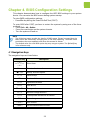
Chapter 4 BIOS Configuration Settings
This chapter introduces the key features of BIOS, including the descriptions and option
keys for diverse functions. These details provide users to effortlessly navigate and
configure the input/output devices.
Chapter 5 BMC Configuration Settings
This chapter illustrates the diverse functions of IPMI BMC, including the details on logging
into the web page and assorted definitions. These descriptions are helpful in configuring
various functions through Web GUI without entering the BIOS setup. For more information
of BMC configurations, please refer to IPMI BMC (Aspeed AST2500) User's Manual for a
more detailed description.
Chapter 6 Technical Support
For more information or suggestion, please contact the nearest AIC® corporation
representative in your district or visit the AIC® website: https://www.aicipc.com/en/index.
It is our greatest honor to provide the best service for our customers.
About This Manual

1
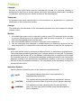
VIRGO
Product specifications and features are subject to change without prior notice�
Chapter 1� Product Features
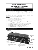
1�1 Components
Dimensions
mm : 304.8 x 330.2
inches : 12 x 13
Serial
Port
VGA
Port
2 x USB 3.0 + RJ45
dedicated NIC for BMC
Intel
®
PCH Integrated
10G (Dual SFP+)
Aspeed AST2500
BMC + Video (IPMI 2.0)
6 x SFF-8643 Connectors
(Supports 6 x PCIe x4 for
NVMe SSD)
2 x 10G SFI by
SFF-8612 (Oculink)
(PCH C624 SKU only)
1 x M.2 Key
(2242/2280) supports
SATA/PCIe x4
3 x PCIe
Gen3 x8 Slot
2 x PCIe
Gen3 x16 Slot
Total 10 x SATA 6Gb/s
(8 Ports by 2 x Mini-SAS +
2 Ports by 7-pin SATA)
2 x Mini-SAS HD
Supports 8 x SAS 12G
Broadcom SAS3008 IOC
Controller (Optional)
Intel® PCH
(Lewisburg)
6 x DDR4 DIMM Slots
6 Channel (from CPU0)
LGA3647 Socket P0 for
Intel® Xeon® Processor
Skylake-SP (CPU0)
6 x DDR4 DIMM Slots
6 Channel (from CPU1)
LGA3647 Socket P0 for
Intel® Xeon® Processor
Skylake-SP (CPU1)

2
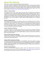
Chapter 1. Product Features
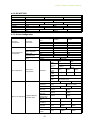
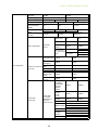
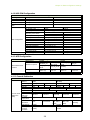
1�2 Specifications
System
Processor
Support
Intel® Xeon® Scalable Processors
(Skylake/Cascade Lake/Cascade Lake Refresh)
CPU TDP
165W
UPI Speeds
10.4 GT/s, 9.6 GT/s
Socket Type
Socket P0 (LGA-3647 Socket)
System
Memory
1 x DIMM per channel
DDR4 2400/2666MHz RDIMM/LRDIMM
(feature supports up to DDR4 2933MHz
by next gen. process upgrade)
- up to 192GB RDIMM SRx4
- up to 384GB RDIMM DRx4
- up to 1536GB RDIMM 3DS 8Rx4
- up to 768GB LRDIMM QRx4
- up to 1536GB LRDIMM 3DS 8Rx4
(Apache Pass) support
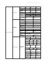
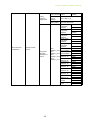
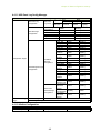
Expansion
Slots
additional bracket) supports SATA/PCIe x4
System BIOS
BIOS Type
Insyde UEFI BIOS
BIOS
Features
redirection
Mode
On-board
Devices
SATA/SAS
Intel® Lewisburg PCH on-chip solution
8 ports 12G SAS via 2 x mini-SAS HD (optional)
BMC
Aspeed AST2500 Advanced PCIe Graphics &
Remote Management Processor
Serial over LAN
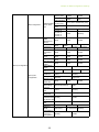
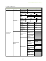
On-board
Devices
Network
Controller
Controller with dual SFP+ rear connectors
(KR/SFI/XFI) by onboard header
(optional by PCH C624 SKU)
BMC dedicated management port
Graphics
Aspeed AST2500 Advanced PCIe Graphics &
Remote Management Processor
Input/Output
Serial ATA
10 x SATA 6.0 Gb/s ports
LAN
dual ports: 10G KR/SFI/XFI
(optional by PCH C624 SKU)
management
USB
USB3.0/USB2.0
VGA
(share with external VGA port)
Serial Port
Other
Additional
Information
SAS (Optional)
ports SAS 12 Gb/s

3
Chapter 1. Product Features
The Virgo server board offers the latest Intel® Xeon® Scalable Processors technology
solutions with compelling performance and provides premium power efficiency, which is
optimized for efficient performance platforms (storage, security and communications in-
frastructure).
By implementing Intel® Xeon® Scalable Processors, fully integrated microarchitecture,
the Virgo server board delivers unmatched performance, providing six channels of DDR4
2400/2666MHz (feature supports up to DDR4 2933MHz by next gen. process upgrade)
per socket, dual 10GbE SFP+ and optional internal connector to support configurable dual
ports for 10GbE (KR/ SFI/XFI) or 1GbE (KX), and optional Broadcom SAS3008 SAS IOC on-
board.
Featured with ground breaking technologies including Intel® Next Generation Microar-
chitecture and Instruction Set (AVX-512, VMD, QAT - optional by PCH SKU), Speed Shift
Technology, UPI link speeds up to 10.4GT/s, the Virgo server board enable next generation
server solutions with an incredible leap in performance in a standard EATX form factor
platform.
• Supports Intel® Xeon® Scalable Processors for highest server performance and
improved power efficiency
• Supports 2 x PCIe Gen3 x16 slots + 3 x PCIe Gen3 x8 slots + 6 x SFF-8643 each
supports PCIe Gen3 x4
• Supports one NGFF (M.2) with PCIe Gen3 x4 / SATA co-design
• Broadcom SAS3008 SAS/SATA I/O Controller for 12Gb/s SAS
• Onboard dual ports 10GbE SFP+ and optional two configurable ports support 10GbE
(KR/SFI/XFI) or 1GbE (KX), by internal connector supported by Intel®Lewisburg PCH
• Onboard Baseboard Management Controller for system management and IPMI control
• Embedded components for 5+ year long life
1�3 Feature

4
Chapter 2� Hardware Setup
This section describes a simple instruction guide for installing the hardware components
on the serverboard system. Turn off and unplug all system and peripheral devices before
proceeding.
2�1 Central Processing Unit Setup
The serverboard supports dual Xeon scalable processors and Socket P0 (LGA-3647).
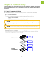
2�1�1 Processor Installation
To ensure a safe and easy setup, you need to prepare before installation:
a T20 Torx screwdriver
ESD wrist strap/mat and conductive foam pad
CAUTION
The pins of the processor socket are vulerable and easily susceptible to damage if fingers or any
foreign objects are pressed against them. Please keep the socket protective cover on when the
processor is not installed.
CAUTION
When unpacking a processor, hold the processor only by its edges to avoid touching the contacts.
Standard Processor Assembly:
A standard processor assembly is comprised of PHM(Processor Heat sink Module)
components and processor socket assembly.
Heat sink
Standard
Processor Clip
Standard
Processor
Bolster Plate
Precsessor
Socket
PHM Components
Processor
Socket Assembly

5
Chapter 2. Hardware Setup
Processor Socker Assembly:
The server board includes two processor sockets (LGA-3647), supports two Intel®
Xeon® Processor Scalable Family and has a Thermal Design Power (TDP) of up to
165W on selected models.
PHM (Processor Heat sink Module) Component:
Non Frabic
Processor
Non Frabic
Processor Clip
Heat sink

6
Chapter 2. Hardware Setup
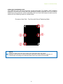
PHM Screw Installation Order:
The PHM sits level with the processor socket assembly. The PHM is NOT installed
properly if it does not sit level with the processor socket assembly. Once the PHM is
seated over the processor socket assembly, the four heat sink torque screws must be
secured in the following order as shown below.
Processor Heat Sink – Top View with Screw Tightening Order
NOTE
Failure to tighten the heat sink screws in the specified order may cause
damage to the processor socket assembly. Heat sink screws should be tighted to 12
in-lbs torque according to the ndicated order on the top of the heat sink label.

7
Chapter 2. Hardware Setup
This server board supports up to twelve DDR4 2400 and 2666 Registered ECC DRAM/
Load-Reduced DIMM (LRDIMM)
2�2 System Memory
NOTE
-In Virgo case, the lanes from CPU#0 are routed to PCIe slots 1 & 5 and onboard SFF-
8643.
-The lanes from CPU#1 are routed to PCIe slots 2/3/4 and the onboard SFF-8643.
2
B18
A18 A1
B1
B18
A18 A1
B1
A1
B21
1
2
3
4
4
1
5
1 2 3 7 8 9
T
R
P
N
M
L
K
J
H
G
F
D
D
C
B
A
7060 6545 50 5535 40
25 3015 205 10
A
C
L
J
G
E
AB
Y
V
R
N
AN
AL
AJ
AF
AD
BD
BB
AY
AV
AR
BU
BN
BR
BL
BJ
BF
CA
BW
144 288
77
222
221
145
1
78
144 288
77
222
221
1451
78
144 288
77
222
221
1451
78
EE
DY
DU
DJ
DA
CN
CE
BU
BJ
BA
AN
AE
U
J
A
8
7
6
5
4
3
2
143
42
41
40
39
38
37
36
35
34
33
32
31
30
29
28
27
26
25
24
23
22
21
20
19
18
17
16
15
14
13
12
11
10
9
79
78
77
76
75
74
73
72
71
70
69
68
67
66
65
64
63
62
61
60
59
58
57
56
55
54
53
52
51
50
49
48
47
46
45
44
86
85
84
83
82
81
80
EE
DY
DU
DJ
DA
CN
CE
BU
BJ
BA
AN
AE
U
J
A
8
7
6
5
4
3
2
1 43
42
41
40
39
38
37
36
35
34
33
32
31
30
29
28
27
26
25
24
23
22
21
20
19
18
17
16
15
14
13
12
11
10
9
79
78
77
76
75
74
73
72
71
70
69
68
67
66
65
64
63
62
61
60
59
58
57
56
55
54
53
52
51
50
49
48
47
46
45
44 86
85
84
83
82
81
80
4
1
1
51 302515 2010
AK
AE
R
Y
K
E
A
123456
A
B
C
D
E
F
G
H
67
68
2
74
75 57
1
A
B
C
D
E
F
G
H
J
K
L
M
N
P
R
T
U
V
W
Y
AA1
AB1
1
2
3
4
5
6
7
8
9
10
11
12
13
14
15
16
17
18
19
20
21
22
1
13
1
20
19
2 1
20
19
2
1
20
19
2
A2
A1
B1
B2
A48
A49
B49
B48
A2
A1
B1
B2
A2
A1
B1
B2
A48
A49
B49
B48
C8
C6
C2
C3
C5
C9
C7
C4
C1
D6
D8
D3
D2
D5
D9
D7
D4
D1B1
B4
B7
B9
B8
B6
B2
B3
B5
A1
A2
A3
A4
A5
A6
A7
A8
A9
C8
C6
C2
C3
C5
C9
C7
C4
C1
D6
D8
D3
D2
D5
D9
D7
D4
D1B1
B4
B7
B9
B8
B6
B2
B3
B5
A1
A2
A3
A4
A5
A6
A7
A8
A9
C8
C6
C2
C3
C5
C9
C7
C4
C1
D6
D8
D3
D2
D5
D9
D7
D4
D1B1
B4
B7
B9
B8
B6
B2
B3
B5
A1
A2
A3
A4
A5
A6
A7
A8
A9
C8
C6
C2
C3
C5
C9
C7
C4
C1
D6
D8
D3
D2
D5
D9
D7
D4
D1B1
B4
B7
B9
B8
B6
B2
B3
B5
A1
A2
A3
A4
A5
A6
A7
A8
A9
A9
A8
A7
A6
A5
A4
A3
A2
A1
B5
B3
B2
B6
B8
B9
B7
B4
B1
D1
D4
D7
D9
D5
D2
D3
D8
D6
C1
C4
C7
C9
C5
C3
C2
C6
C8
A9
A8
A7
A6
A5
A4
A3
A2
A1
B5
B3
B2
B6
B8
B9
B7
B4
B1 D1
D4
D7
D9
D5
D2
D3
D8
D6
C1
C4
C7
C9
C5
C3
C2
C6
C8
A9
A8
A7
A6
A5
A4
A3
A2
A1
B5
B3
B2
B6
B8
B9
B7
B4
B1 D1
D4
D7
D9
D5
D2
D3
D8
D6
C1
C4
C7
C9
C5
C3
C2
C6
C8
A9
A8
A7
A6
A5
A4
A3
A2
A1
B5
B3
B2
B6
B8
B9
B7
B4
B1 D1
D4
D7
D9
D5
D2
D3
D8
D6
C1
C4
C7
C9
C5
C3
C2
C6
C8
S
E
B
1
5
4
1
5
8
4
4
85
1
1
11
10
20
2
11
12
1
1
2
2
9
10
1
2
9
10
1
1
10
9
2
1
9
2
2
9
10
1
2
10
1
2
9 10
1
1
6
5
2
1
6
5
2
1
6
5
2
2
1
2
1
2
1
2
1 2 1 2
2
1
2
1
2
1
2
1
2
1
1
2
1
2
1
2
1
2
1
1
2
4
4
R9
R1
U14 U18
U4
U1
3
1
3
1
12
2324
5 9
14
1814
6
16
1
6
1
6
6
1
6
1
3
56
8
10
11
12
14
15
pcb outline
pcb outline
A2
A1
B1
B2
A82
A81
B81
B82
A2
A1
B1
B2
A82
A81
B81
B82
+
223
220
76
78
221
222
77
79
287
288
143
144
223
220
76
78
1
145
146
221
222
7779
287
288
143
144
223
220
76
78
1
145
146
221
222
77 79
287
288
143
144
223
220
76
78
1
145
146
221
222
77 79
287
288
143
144
223
220
76
78
1
145
146
221
222
77 79
287
288
143
144
223
220
76
78
1
145
146
221
222
7779
287
288
143
144
223
220
76
78
1
145
146
221
222
7779
287
288
143
144
223
220
76
78
221
222
7779
287
288
143
144
223
220
76
78
1
221
222
77
79
287
288
143
144
1
5
6
1
2
34
5
789
pcb outline
pcb outline
9
CPU1CPU1
CPU0CPU0
JDIMML0
JDIMMK0
JDIMMJ0
JDIMML0
JDIMMK0
JDIMMJ0
JDIMMG0
JDIMMH0
JDIMMI0
JDIMMG0
JDIMMH0
JDIMMI0
JDIMMC0
JDIMMB0
JDIMMA0
JDIMMC0
JDIMMB0
JDIMMA0
JDIMMD0
JDIMME0
JDIMMF0
JDIMMD0
JDIMME0
JDIMMF0
1
SFF-8643
2
SFF-8643
PCIE5
PCIE4
PCIE3
PCIE2
PCIE1

8
Chapter 2. Hardware Setup
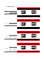
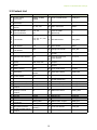
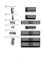
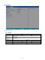
2�2�1 DIMM Population
DIMM Numbers DIMM ARRANGMENT
2 DIMMs
CPU1 CPU0
JDIMM_L0 JDIMM_C0
JDIMML0
JDIMMC0
JDIMMK0
JDIMMB0
JDIMMJ0
JDIMMA0
JDIMMG0
JDIMMD0
JDIMMH0
JDIMME0
JDIMMI0
JDIMMF0
CPU 1
CPU 1
CPU 1
CPU 0
CPU 0
CPU 0
JDIMML0
JDIMMC0
JDIMMK0
JDIMMB0
JDIMMJ0
JDIMMA0
JDIMMG0
JDIMMD0
JDIMMH0
JDIMME0
JDIMMI0
JDIMMF0
CPU 1
CPU 1
CPU 1
CPU 0
CPU 0
CPU 0
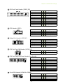
4 DIMMs
CPU1 CPU0
JDIMM_L0 JDIMM_C0
JDIMM_J0 JDIMM_A0
JDIMML0
JDIMMC0
JDIMMK0
JDIMMB0
JDIMMJ0
JDIMMA0
JDIMMG0
JDIMMD0
JDIMMH0
JDIMME0
JDIMMI0
JDIMMF0
CPU 1
CPU 1
CPU 1
CPU 0
CPU 0
CPU 0
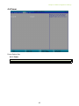
6 DIMMs
CPU1 CPU0
JDIMM_L0 JDIMM_C0
JDIMM_J0 JDIMM_A0
JDIMM_I0 JDIMM_F0
JDIMML0
JDIMMC0
JDIMMK0
JDIMMB0
JDIMMJ0
JDIMMA0
JDIMMG0
JDIMMD0
JDIMMH0
JDIMME0
JDIMMI0
JDIMMF0
CPU 1
CPU 1
CPU 1
CPU 0
CPU 0
CPU 0
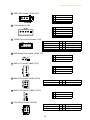
8 DIMMs
CPU1 CPU0
JDIMM_L0 JDIMM_C0
JDIMM_J0 JDIMM_A0
JDIMM_G0 JDIMM_D0
JDIMM_I0 JDIMM_F0

9
Chapter 2. Hardware Setup
JDIMML0
JDIMMC0
JDIMMK0
JDIMMB0
JDIMMJ0
JDIMMA0
JDIMMG0
JDIMMD0
JDIMMH0
JDIMME0
JDIMMI0
JDIMMF0
CPU 1
CPU 1
CPU 1
CPU 0
CPU 0
CPU 0
CPU1 CPU0
JDIMM_ L0 JDIMM_ C0
JDIMM_ K0 JDIMM_ B0
JDIMM_ J0 JDIMM_ A0
JDIMM_ G0 JDIMM_ D0
JDIMM_ I0 JDIMM_ F0
10 DIMMs
JDIMML0
JDIMMC0
JDIMMK0
JDIMMB0
JDIMMJ0
JDIMMA0
JDIMMG0
JDIMMD0
JDIMMH0
JDIMME0
JDIMMI0
JDIMMF0
CPU 1
CPU 1
CPU 1
CPU 0
CPU 0
CPU 0
CPU1 CPU0
JDIMM_ L0 JDIMM_ C0
JDIMM_ K0 JDIMM_ B0
JDIMM_ J0 JDIMM_ A0
JDIMM_ G0 JDIMM_ D0
JDIMM_ H0 JDIMM_ E0
JDIMM_ I0 JDIMM_ F0
12 DIMMs

10
Chapter 2. Hardware Setup
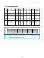
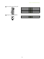
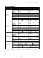
2�2�2 DCPMM DIMM Population
CPU0 CPU1
DIMM JDIMMF0 JDIMME0 JDIMMD0 JDIMMA0 JDIMMB0 JDIMMC0 JDIMML0 JDIMMK0 JDIMMJ0 JDIMMG0 JDIMMH0 JDIMMI0
App Direct
Mode
DCPMM DRAM1 DRAM1 DRAM1 DRAM1 DCPMM - - - - - -
Memory
Mode
DCPMM DRAM2 DRAM2 DRAM2 DRAM2 DCPMM
-
- - - - -
Mixed
Memory
Mode
DCPMM DRAM3 DRAM3 DRAM3 DRAM3 DCPMM - - - - - -
App Direct
Mode
DCPMM DRAM1 DRAM1 DRAM1 DRAM1 DCPMM DCPMM DRAM1 DRAM1 DRAM1 DRAM1 DCPMM
Memory
Mode
DCPMM DRAM2 DRAM2 DRAM2 DRAM2 DCPMM DCPMM DRAM2 DRAM2 DRAM2 DRAM2 DCPMM
Mixed
Memory
Mode
DCPMM DRAM3 DRAM3 DRAM3 DRAM3 DCPMM DCPMM DRAM3 DRAM3 DRAM3 DRAM3 DCPMM
NOTE
DIMM Type RDIMM 3DS RDIMM LRDIMM 3DS LRDIMM Capacity
DRAM1
Any Capacity
DRAM2
≥32GB
DRAM3
Any Capacity
DCPMM Any Capacity (Uniformly for all channels for system configuration)
NOTE
Please abide to the DCPMM population rules listed below for your system to function accordingly.
• There is only a maximun of 1 DCPMM in each channel.
• Populate DCPMM DIMM on IMC0 before IMC1.

11
Chapter 2. Hardware Setup
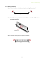
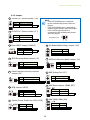
2�2�3 Memory Installation
Step 1 Unlock the dimm socket by pressing the retaining clips outward.
Step 2 Insert the memory module into the slot. Make sure that the DIMM notch is
accurately positioned.
Step 3 Close the retaining clips to complete installation.
DIMM n
otch

12
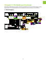
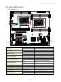
This section describes the jumpers, internal connectors and internal LEDs setting on Virgo
motherboard. The motherboard layout and important jumper settings are listed below.
3�1 Block Diagram
Chapter 3� Motherboard Settings
DMI GEN3@8GT/s
LGA3647-0 Socket
SPI Flash
W25Q64BVSSIG
CPU TDP 165W
Platform Environment Control Interface(PECI)
DMI3 x 4
MX25L51245GMI-10G
Flash
Debug port
USB#3
USB#2
ECC DDR4 (1866/2133/2400/2667)
CPU0
MUX
USB#0
USB#1
DIMM #A0
DIMM #B0
DIMM #C0
DIMM #D0
DIMM #E0
CPU0_VRD
VR13
XDP
Skylake-SP
(Cascade Lake-SP)
CPU1
LGA3647-0 Socket
DIMM #G0
CPU TDP 165W
DIMM #I0 DIMM #K0
DIMM #L0
ECC DDR4 (1866/2133/2400/2667)
TDP 19W
Lewisburg-4
PCH
SATAPort #0~9
SATA#0
SATA#1
SATA#2
SATA#3
PCIe slot X8 (Support NTB)
PCIe slot X16
Port3(IOU2)
PCI-E GEN3 @8GT/s X8
Port2(IOU1)
PCI-E GEN3 @8GT/s X16
Port3(IOU2) Port1(IOU0)
LPC/eSPI
Platform Environment Control Interface(PECI)
@6Gb/s
SATA#6
SATA#7
USB2.0 Port #0~3
@5Gb/s
USB3.0 Port #0~3
DIMM #F0DIMM #H0 DIMM #J0
CPU1_VRD
VR13
PCIe slot2
PCIe slot3
PCIe slot4
PCIe slot5
Port2(IOU1)
NGFF M.2 2242/2280
MUX x1
PCIE x4 or SATA x1
PCI-E GEN3 @8GT/s X4 & SATA @6Gb/s
SATAPort #10
@6Gb/s
SATA#8
SATA#9
PCI Express x 4
PCI Express x 16
PCIe slot X16
PCI-E GEN3 @8GT/s X16
LSI
SAS3008
SASPort x4
@12Gb/s
SASPort x4
@12Gb/s
PCI Express x 16
S25FL256SAGMFI001
NVSRAM
CY14V101LA-BA25
Flash
UART0
Debug port
ICE0
Debug port
PCIe slot X8
PCI-E GEN3 @8GT/s X8
Port1(IOU0)
PCIE x 8
PCI-E GEN3@8GT/s
SFF-8643
SFF-8643
PCI Express x 4
Port1a(IOU0)
Port1c(IOU0)
Port1d(IOU0)
PCI Express x 8
Port3c(IOU2)
Port2a(IOU1)
Port2a(IOU1)
Skylake-SP
(Cascade Lake-SP)
Port3a(IOU2)
PCI Express x 4
SATA#4
SPI
NUVOTON
NPCT650
SPI Flash
W25Q256FVFIQ
TPM 2.0
(Internal Box Header )
Edge Connector
RJ45 x1
SPI
SPI2
USB(X2)
RMII
Aspeed AST2500
VGA CONN
VGA Pin Header
PCI Express x 1
COM1
(DB-9 CONN)
Pin Header
BMC Debug
Box Header
COM2
(1x3 pin)
JCOM4
(2x5 pin)
USB(X2)
ADM213
ADM213
COM5
USB2.0 Port #4~5
Box Header
(2x5 pin)
SFP x2
NCSI
ADM213
COM1
AST_USB Port #0~1 to PCH Port #4~5
EDY4016AABG-DR-F-D
DDR4 x16
COM4
LCM
Pin Header
(1x5 pin)
Secure boot key
PCI Express x 8
Port3c(IOU2)
PCI Express x 8
UPI
UPI @10.4GT/s
UPI1 UPI0
UPI0UPI1
UPI
UPI @10.4GT/s
SFF-8643
SFF-8643
PCIe slot X8 (Support NTB)
PCIe slot1
PCI Express x 8
Port3a(IOU2)
PCI-E GEN3 @8GT/s X8
SFF-8643
SFF-8643
SFF-8643
SFF-8643
Port1a(IOU0)
PCI Express x 4
Port1b(IOU0)
PCI Express x 4
Port1c(IOU0)
PCI Express x 4
Port1d(IOU0)
PCI Express x 4
10/100Mbps dedicate
management port
RTL8201EL
SFIx2
SFIx2
I2C4
LM95241CIMM
LM95241CIMM-1
LM95241CIMM-2
SFF-8612
SATA#5
PCI-E GEN3 @8GT/s X4
PCI-E GEN3 @8GT/s X4
PCI-E GEN3 @8GT/s X4
PCI-E GEN3 @8GT/s X4
PCI-E GEN3 @8GT/s X4
PCI-E GEN3 @8GT/s X4
Page is loading ...
Page is loading ...
Page is loading ...
Page is loading ...
Page is loading ...
Page is loading ...
Page is loading ...
Page is loading ...
Page is loading ...
Page is loading ...
Page is loading ...
Page is loading ...
Page is loading ...
Page is loading ...
Page is loading ...
Page is loading ...
Page is loading ...
Page is loading ...
Page is loading ...
Page is loading ...
Page is loading ...
Page is loading ...
Page is loading ...
Page is loading ...
Page is loading ...
Page is loading ...
Page is loading ...
Page is loading ...
Page is loading ...
Page is loading ...
Page is loading ...
Page is loading ...
Page is loading ...
Page is loading ...
Page is loading ...
Page is loading ...
Page is loading ...
Page is loading ...
Page is loading ...
Page is loading ...
Page is loading ...
Page is loading ...
Page is loading ...
Page is loading ...
-
 1
1
-
 2
2
-
 3
3
-
 4
4
-
 5
5
-
 6
6
-
 7
7
-
 8
8
-
 9
9
-
 10
10
-
 11
11
-
 12
12
-
 13
13
-
 14
14
-
 15
15
-
 16
16
-
 17
17
-
 18
18
-
 19
19
-
 20
20
-
 21
21
-
 22
22
-
 23
23
-
 24
24
-
 25
25
-
 26
26
-
 27
27
-
 28
28
-
 29
29
-
 30
30
-
 31
31
-
 32
32
-
 33
33
-
 34
34
-
 35
35
-
 36
36
-
 37
37
-
 38
38
-
 39
39
-
 40
40
-
 41
41
-
 42
42
-
 43
43
-
 44
44
-
 45
45
-
 46
46
-
 47
47
-
 48
48
-
 49
49
-
 50
50
-
 51
51
-
 52
52
-
 53
53
-
 54
54
-
 55
55
-
 56
56
-
 57
57
-
 58
58
-
 59
59
-
 60
60
-
 61
61
-
 62
62
-
 63
63
-
 64
64


Ask a question and I''ll find the answer in the document
Finding information in a document is now easier with AI
Related papers
Other documents
-
Gigabyte S461-3T0 User manual
-
Intel Optane Persistent Memory and SAP HANA Platform User guide
-
-
DFI PL610-C622 Owner's manual
-
Supermicro X11OP Series User manual
-
-
-
 ANTAIRA USB-HUB4K3 Installation guide
-
-
