Page is loading ...

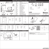
No. Code Descripon
1 LED_LAN1 SFP+ LAN port#1 Acve LED
2 SFP+_1_2 SFP+ LAN port #1 (Le)
SFP+ LAN port #2 (Right)
3 LED_LAN2 SFP+ LAN#2 link/Acve LED
4 SW_ID ID buon with LED
5 LAN1_2 GbE LAN port #1 (Le)
GbE LAN port #2 (Right)
6 VGA VGA port
7 COM1 Serial port cable connector
8 U2_0 Slimline connector #1 (PCIe x4 signal)
9 U2_1 Slimline connector #2(PCIe x4 signal)
10 MEZZ_2 PCIe x 8 slot (Proprietary/for mezzanine card)
11 MEZZ_1 PCIe x 8 slot (Proprietary/for mezzanine card)
12 USB3_MLAN Sever management LAN port (top)/USB 3.0 ports (buom)
13 BAT Baery socket
14 PMBUS PMBus connector
15 ATX1 2x12 pin main power connector
16 SYS_FAN5 System fan connector#5
17 CPU1_FAN1 CPU fan connector (for secondary CPU)
18 CPU0_FAN1 CPU fan connector (for primary CPU)
19 P12V_AUX2 2x4 pin 12V power connector (for secondary CPU)
20 SYS_FAN4 System fan connector#4
21 SYS_FAN3 System fan connector#3
22 SYS_FAN2 System fan connector#2
23 P12V_AUX1 2x4 pin 12V power connector (for primary CPU)
24 SYS_FAN1 System fan connector#1
25 SW_RAID VROC key
26 LAN4_AC1 LAN#4 Acve LED
27 LAN3_AC1 LAN#3 Acve LED
28 FP_1 Front panel header
29 J2 Funcon jumper switch #2
30 J1 Funcon jumper switch #1
31 CLR_CMOS Clear CMOS jumper
32 Error LED for DIMM slots
33 F_USB3 USB 3.0 header
34 SL_CN1 Slimline connector #1 (SATA 6Gb/s signal/for SATA#0~#3)
35 SL_CN2 Slimline connector #2 (SATA 6Gb/s signal/for SATA#4~#7)
36 SL_CN3 Slimline connector #3 (SATA 6Gb/s signal/for sSATA#0~#3)
No. Code Descripon
37 SSATA5 SATA 6Gb/s connector #5
38 SATA_DOM1 SATA DOM support power connector for SSATA port #5
39 TPM TPM connector
40 LED_BMC BMC firmware readiness LED
41 IPMB IPMB connector
42 PCIE_4 PCIe x16 slot #4 (Gen3 x16)
43 PCIE_3 PCIe x16 slot #3 (Gen3 x16)
44 PCIE_2 PCIe x16 slot #2 (Gen3 x16)
45 PCIE_1 PCIe x16 slot #1 (Gen3 x16)
46 SSATA4 SATA 6Gb/s connector #4
47 SATA_DOM0 SATA DOM support power connector for SSATA port #4
&38
3ULPDU\
1 2 3 4 5
7
89
13
11
10
14
15
16
17
18
19
20
21
22
23
24
25
26
27
28
47
46
31
32
30
29
33
35 34 36
38
39
37
45 44 43 42
40
41
6 12
Front Panel Header #1
1
2423
2
No. Pin Define
1 Power LED+
3 No Pin
5 Power LED-
7 HDD LED+
9 HDD LED-
11 Power Buon
13 GND
15 Reset Buon
17 GND
19 ID Buon
21 GND
23 NMI Switch
No. Pin Define
2 5V Standby
4 ID LED+
6 ID LED-
8 System Status LED+
10 System Status LED-
12 LAN1 Acve LED+
14 LAN1 Link LED-
16 SMBus Data
18 SMBus Clock
20 Case Open
22 LAN2 Acve LED+
24 LAN2 Link LED-
ATX Power
No. Pin Define
1 GND
2 GND
3 GND
4 GND
5 +12V
6 +12V
7 +12V
8 +12V
24 12
13
1
No. Pin Define
1 3.3V
2 3.3V
3 GND
4 +5V
5 GND
6 +5V
7 GND
8 Power Good
9 5VSB
10 +12V
11 +12V
12 3.3V
No. Pin Define
13 3.3V
14 -12V
15 GND
16 PS_ON
17 GND
18 GND
19 GND
20 -5V
21 +5V
22 +5V
23 +5V
24 GND
8 4
5 1
1 5
4 8
PMBUS
1
5No. Pin Define
1 PMBus Clock
2 PMBus Data
3 PMBus Alert
4 GND
5 3.3V Sense
Installing CPU and Heat Sink
4
1
4
3
2
1
2
3
Memory Populaon Configuraon
Intel Optane DCPMM DIMM Populaon Rule
Modes
iMC0
Slot1
Channel0Channel1Channel2 Channel0Channel1Channel2
Slot0 Slot1 Slot0 Slot1 Slot0 Slot1 Slot0 Slot1 Slot0 Slot1 Slot0
iMC1
DRAM1
DRAM2
DRAM3
DRAM1
DRAM2
DRAM3
DRAM1
DRAM2
DRAM3
Symmetric Populaon with the Socket
AD --
--
--
--
--
--
--
--
--
DCPMM
MM DCPMM
AD+MM DCPMM
DRAM1
DRAM2
DRAM3
DRAM1
DRAM2
DRAM3
DRAM1
DRAM2
DRAM3
--
--
--
DCPMM
DCPMM
DCPMM
2-1-1
2-1-1
2-1-1
Modes
iMC0
Slot1
Channel0Channel1Channel2 Channel0Channel1Channel2
Slot0 Slot1 Slot0 Slot1 Slot0 Slot1 Slot0 Slot1 Slot0 Slot1 Slot0
iMC1
DRAM1
DRAM1
DRAM1
DRAM1
DRAM1
DRAM1
Asymmetric Populaon with the Socket
AD --
--
--
--
--
--
--
--
AD*
DRAM1
DRAM1
DRAM1
DRAM1
DRAM1
DRAM1
--
--
DCPMM
DCPMM
2/1-1-1
2/1-1-1
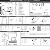
No. Desripon
1 Server Management LAN port
2 USB 3.0 ports
3 VGA port
4 GbE Ethernet LAN port #2
5 GbE Ethernet LAN port #1
6 ID buon with LED
7 SFP+ LAN#2 link/Acve LED
8 SFP+ LAN port #2
9 SFP+ LAN port #1
10 SFP+ LAN#1 link/Acve LED
1
234 5 7
698 10
ID buon/LED:
Blue On System identifcation
is active.
Off System identifcation
is disabled.
State Description
State Description
Yellow On 1 Gbps data rate
Green On 10 Gbps data rate
SFP+ LAN LED:
Off 10Mbps data rate
State Description
Yellow On 1Gbps data rate
Green On 100Mbps data rate
10/100/1000 LAN LED:
Speed LED Link/Acvity
LED
Green LED
Yellow LED
SATA Connector/SATA DOM
9
1
No. Pin Define
1 GND
2 TXP
3 TXN
4 GND
5 RXN
6 RXP
7 GND
8 5V
9 GND
13
1
3
No. Pin Define
1 5V
2 GND
3 No Connect
TPM Connector
14
13
2
1
No. Pin Define
1 Clock
2 P_3V3_AUX
3 SPI_RST
4 P3V3
5 SPI_MISO
6 IRQ_SERIAL
7 SPI_MOSI
No. Pin Define
8 No Connect
9 No Connect
10 No Pin
11 No Connect
12 GND
13 SPI_CS
14 GND
IPMB
41
No. Pin Define
1 Clock
2 GND
3 Data
4 VCC
CPU/System FAN
4 1
1 4 No. Pin Define
1 GND
2 +12V
3 Sense
4 Speed Control
USB 3.0 Header
120
1011
No. Pin Define
1 Power
2 IntA_P1_SSRX-
3 IntA_P1_SSRX+
4 GND
5 IntA_P1_SSTX-
6 IntA_P1_SSTX+
7 GND
8 IntA_P1_D-
9 IntA_P1_D+
10 NC
No. Pin Define
11 IntA_P2_D+
12 IntA_P2_D-
13 GND
14 IntA_P2_SSTX+
15 IntA_P2_SSTX-
16 GND
17 IntA_P2_SSRX+
18 IntA_P2_SSRX-
19 Power
20 No Pin
COM2 Connector
No. Pin Define
1 NDCD-
2 NSIN
3 NSOUT
4 NDTR-
5 GND
6 NDSR-
7 NRTS-
8 NCTS-
9 NRI-
10 No Pin
2 1
10 9
1
Jumper Sengs
No. Desripon
1 Clear CMOS Jumper
1-2 Close: Normal operaon (Default seng)
2-3 Close: Clear CMOS data.
Rear I/O Connector
HOST_SMBUS_SEL
PMBUS_SEL
ON
CPLD debug mode
Clear supervisor password
BIOS recovery mode
Force ME update
Normal [Default]
OFF
S3_MASK
DB_PLD
J1
1
2
3
4
ME_UPDATE
BIOS_PWD
ON
ME recovery mode Normal [Default]
Normal [Default]
Normal [Default]
Normal [Default]
OFF
BIOS_RCVR
ME_RCVR
J2
1
2
3
4
BIOS defined
BIOS defined
BIOS defined
BMC Firmware Readiness LED
State Descripon
On BMC firmware is inial
Blink BMC firmware is ready
Off AC loss
BMC Firmware Readiness LED (LED_BMC1):
MD61-SC2 Quick Reference Guide
Description
Normal operation
Error/DIMM missing
State
Off
Red On
DIMM Status LED:
Description
DIMM
Capacity
(GB)
DIMM Density
1 Slot per
Channel 2 Slot per Channel
Speed (MT/s); Voltage (V)
Slot Per Channel (SPC)
DIMM Per Channel (DPC)
1DPC 1DPC 2DPC
1.2V
2933 2933 2666
1.2V 1.2V
Ranks Per
DIMM and
Data Width
4Gb 8Gb
4GB 8GB
8GB 16GB
8GB 16GB
16GB
32GB
N/A
N/A
2H-64GB
4H-128GB
N/A
N/A 4H- 128GB
32GB
64GB
2H-64GB
8Gb
16GB
32GB
32GB
2H-128GB
4H-256GB
4H-256GB
64GB
128GB
2H -128GB
Type
RDIMM
RDIMM
RDIMM
RDIMM
LRDIMM
LRDIMM
3DS
RDIMM
3DS
QRx 4
8Rx 4
QRx4
SRx4
SRx8
DRx8
DRx4
QRx4
8Rx4
NOTE!
1. 2933MHz for 2nd Generaon Intel® Xeon® Scalable Processors only
2. Intel® Optane™ DC Persistent Memory for 2nd Generaon Intel® Xeon®
Scalable Processors only
* 2nd socket has no DCPMM DIMM
AD=All Modes; MM= Memory Mode.
For MM, general NM/FM rao is between 1:4 and 1:16. Excess capacity for FM can be used for AD (NM= Near Memory; FM= Far Memory)
For each individual populaon, sockets are normally symmetric with excepons for 1DCPMM per socket and 1 DCPMM per node case.
No DDR4 single rank x8 for either DCPMM Memory Mode or APP-Direct Mode
No mixing of DCPMM and NVDIMMs within the plaorm.
DDR channel and DIMM slot nomenclature may vary depending on plaorm implementaon.
Matrix targets configs for opmized Intel Optane DCPMM to DRAM cache rao in MM and MM + AD modes.
-- -- --
--
DRAM1
DRAM2
DRAM3
RDIMM
DCPMM Any Capacity (uniformly for all channels for a given configuraon
LRDIMM
LRDIMM 3DS LRDIMM3DS RDIMM
3DS RDIMM
RDIMM
RDIMM
Capacity
Capacity
DDR4 Type
See Validaon Matrix
(DDR4 DIMMs Vaildated
with DCPMM*)

Regulatory Noces Connect With Us
WEEE Symbol Statement
The symbol shown below is on the product or on its packaging, which indicates that this product must not be disposed of with other
waste. Instead, the device should be taken to the waste collecon centers for acvaon of the treatment, collecon, recycling and
disposal procedure. The separate collecon and recycling of your waste equipment at the me of disposal will help to conserve
natural resources and ensure that it is recycled in a manner that protects human health and the environment.
For more informaon about where you can drop off your waste equipment for recycling, please contact your local government
office, your household waste disposal service or where you purchased the product for details of environmentally safe recycling.
When your electrical or electronic equipment is no longer useful to you, "take it back" to your local or regional waste
collecon administraon for recycling.
If you need further assistance in recycling, reusing in your "end of life" product, you may contact us at the Customer Care
number listed in your product's user's manual and we will be glad to help you with your effort.
GIGABYTE产品未故意添加和使用有害物质(Cd、Pb、Hg、Cr+6、PBDE和PBB)。所有部件和元件均经过严格挑选,符合RoHS要求。此
外,我们GIGABYTE一直致力于开发不使用国际上禁止的有毒化学品的产品。
GIGABYTE products have not intended to add and safe from hazardous substances (Cd, Pb, Hg, Cr+6, PBDE and PBB). The parts and components
have been carefully selected to meet RoHS requirement. Moreover, we at GIGABYTE are connuing our efforts to develop products that do not use
internaonally banned toxic chemicals.
Restricon of Hazardous Substances (RoHS) Direcve Statement
限制使用有害物质 (RoHS) 指令声明
California Proposion 65 Warning
WARNING:
This product can expose you to chemicals including Lead, which is known to the State of California to cause cancer, and Bisphenol A
(BPA), which is known to the State of California to cause birth defects or other reproducve harm. For more informaon go to
www.P65Warnings.ca.gov.
Baery Warning:
Incorrectly installing a baery or using incompable baery may increase the risk of ifre explosion. Replace the baery only with
the same or equivalent type.
Do not disassemble, crush, punchture baeries.
Do not store or place your baery pack next to or in a heat source such as a fire, heatgenerang appliance, can or exhaust
vent. Heang baery cells to temperatures above 65oC (149oF) can cause explosion or fire.
Do not aempt to open or service baeries. Do not dispose of baeries in a fire or with household waste.
电池警告:
电池安装不当或使用不兼容的电池会增加火灾爆炸风险。更换电池时,只可使用相同或同等类型的电池。
请勿拆解、挤压、刺破电池。
请勿将电池存放或放置在热源中或旁边,如火源、产生热的设备、罐体或排气口。电池温度升至65oC (149oF)以上
可能导致爆炸或火灾。
请勿尝试打开或维修电池。电池废弃时,请勿投入火中或者作为家庭废弃物进行处理。
依照中华人民共和国的有毒有害物质的限制要求(China RoHS)提供以下的表格:
中华人民共和国电子信息产品中有毒有害物质或元素的名称及含量标识格式
For more informaon, visit our website at:
hp://www.gigabyte.com
Are you a GIGABYTE server reseller?
Get access to our complete source of sales & markeng materials at:
hp://reseller.b2b.gigabyte.com
Jonnect with GIGABYTE directly through the following channels
Email: server.grp@gigabyte.com
Facebook: hps://www.facebook.com/gigabyteserver
Twier: hps://twier.com/GIGABYTEServer
/