
Preferred
TM
Fan-Powered Evaporative Humidier
PF845411 & PF845412
READ AND SAVE THESE INSTRUCTIONS

Preferred
TM
Model PF845411/PF845412
Installation, Operation, & Maintenance Manual
2 Preferred Products
READ AND SAVE THESE INSTRUCTIONS
LIRE ET CONSERVER CES INSTRUCTIONS
TABLE OF CONTENTS
1. Warranty Statement .................................................................................................................................3
2. Safety Warnings .......................................................................................................................................3
3. Introduction ..............................................................................................................................................4
3.1 Basic Operation ..............................................................................................................................4
3.2 Specications Table ........................................................................................................................ 4
3.3 What’s in the Box ...........................................................................................................................4
4. Installation ................................................................................................................................................ 4
4.1 Clearances .....................................................................................................................................4
4.2 Mounting.........................................................................................................................................4
4.3. Plumbing ........................................................................................................................................6
4.4. Electrical/Wiring ..............................................................................................................................7
4.4.1 Wiring PF845411 (without water saving controls) .............................................................. 7
4.4.2 Wiring PF845412 (with water saving controls) ................................................................... 7
5. Operation .................................................................................................................................................7
5.1 Preliminary Checkout .....................................................................................................................7
5.2 Starting and Stopping the humidier ..............................................................................................7
5.3 End Of Season Decommissioning..................................................................................................8
6. Maintenance/Troubleshooting ..................................................................................................................8
6.1 Pad Replacement ...........................................................................................................................8
6.2 Control Board Faults & Reset.........................................................................................................8
6.3 Troubleshooting Chart .................................................................................................................... 9
6.4 Exploded View/Parts List ................................................................................................................10

Preferred
TM
Model PF845411/PF845412
Installation, Operation, & Maintenance Manual
3
Preferred Products
1. Warranty
This product comes with a ve (5) year limited warranty on parts. The
warranty provides that a replacement will be furnished for any part of
the product that fails in normal use and service during the applicable
warranty period specied, in accordance with the warranty’s terms. The
replacement part is warranted for only the unexpired portion of the origi-
nal warranty.
All parts are warranted for a period of FIVE (5) YEARS after the effec-
tive date. The effective date is the date of installation if properly docu-
mented. Otherwise, it is the date of manufacture plus Sixty (60) months.
STANDARD PROVISIONS AND CONDITIONS
The following terms are common to all of Preferred’s individual product
warranties.
THIS WARRANTY WILL NOT APPLY: a) to defects or malfunctions re-
sulting from failure to properly install, operate or maintain the unit in
accordance with the manufacturer’s printed instructions; b) to damage
from abuse, accident, re, ood, and the like; c) to parts used in con-
nection with normal maintenance, such as cleaning or replacing air l-
ters; d) to units that are not installed in the United States of America or
Canada; e) to units that are not installed in accordance with applicable
local codes, ordinances and good trade practices; or f) to defects or
damage caused by the use of any attachment, accessory or component
not authorized by Preferred.
SHIPPING COSTS: You will be responsible for the cost of shipping war-
ranty replacement parts from our factory to our Preferred distributor and
from the distributor to the location of your product. You also are respon-
sible for any shipping cost of returning the failed part to the distributor.
(If in Alaska, Hawaii, or Canada, you also must pay the shipping cost
of returning the failed part to the port of entry into the continental U.S.)
SERVICE LABOR RESPONSIBILITY: This Warranty does not cover
any labor expenses for service, nor for removing or reinstalling parts. All
such expenses are your responsibility, unless a service labor agreement
exists between you and your contractor.
HOW TO OBTAIN WARRANTY PERFORMANCE: You must promptly
report any failure covered by this warranty to the installing contractor or
distributor. Normally, the installing contractor from whom the unit was
purchased will be able to take the necessary corrective action by ob-
taining through his Preferred distributor any replacement parts. If the
contractor is not available, simply contact any other local contractor
handling Preferred products.
The name and location of a local contractor can usually be found in your
telephone directory or by contacting a Preferred distributor. If necessary,
the following Preferred ofce can advise you of the nearest Preferred
distributor:
4744 Island Ford Road • Randleman, NC 27317 • www.askpreferred.
com
HOWEVER, ANY REPLACEMENTS ARE MADE SUBJECT TO VALI-
DATION BY Preferred OF IN WARRANTY COVERAGE.
An item to be replaced must be made available in exchange for the
replacement.
MISCELLANEOUS: No one is authorized to make any warranties on
behalf of Preferred. ANY IMPLIED WARRANTIES, INCLUDING MER-
CHANTABILITY OR FITNESS FOR A PARTICULAR PURPOSE, SHALL
NOT EXTEND BEYOND THE APPLICABLE WARRANTY PERIODS
SPECIFIED ABOVE, Preferred SOLE LIABILITY WITH RESPECT TO
DEFECTIVE PARTS SHALL BE AS SET FORTH IN THIS WARRANTY,
AND ANY CLAIMS FOR INCIDENTAL OR CONSEQUENTIAL DAMAG-
ES ARE EXPRESSLY EXCLUDED. Some states do not allow limitations
on how long an implied warranty lasts, or for the exclusion of incidental
or consequential damages, so the above limitation or exclusion may not
apply to you.
This Warranty gives you specic legal rights, and you may also have
other rights that vary from state to state.
2. Safety & Warnings
!
DANGER
RISK OF ELECTRIC SHOCK
Before cleaning, servicing, or parts replacement, the unit
must be disconnected from all sources of electricity. Failure to
comply may result in serious injury or death.
!
WARNING
Improper installation, adjustment, alteration, service, or main-
tenance may cause property damage, injury, or death. This
appliance must be installed according to these instructions.
Read these instructions thoroughly before installing or servic-
ing the unit.
!
CAUTION
Read these instructions thoroughly before installing this unit.
Check data label and verify electrical specications agree
with those at the point of installation.
!
WARNING
Failure to install this unit in a position that is level and plumb
may impair the unit’s ability to drain if an overow condition
presents itself. Damage to personal property may also result.
!
WARNING
Installation in freezing conditions can result in unit failure.
Damage to personal property may also result.

Preferred
TM
Model PF845411/PF845412
Installation, Operation, & Maintenance Manual
4 Preferred Products
3. Introduction
The benets of a properly humidied environment (35-50%
Relative Humidity) are many. They include both personal com-
fort as well as the preservation of furniture, draperies, carpets,
wooden oors and cabinets, paintings, pianos, etc. Your home
can be more comfortable at a lower temperature (i.e.: 68° F)
at 30-40% Relative Humidity (RH) than at 71° to 72° F with-
out controlled humidity. Since every degree of temperature
setback represents about 3% of your heating costs, this can
possibly represent a signicant annual savings. During the heat-
ing season, cold air inltrates the home and must be heated.
When heated, this air dries out and greatly increases its
capacity to hold more moisture. By using a humidier, a
source of water is provided to satisfy this increased mois-
ture holding capability, rather than having it drawn from our
body surface and the surrounding furnishings in the home.
3.1 Basic Operation
Your Preferred
TM
fan-powered evaporative humidier oper-
ates on the principles of evaporation. Water is introduced to
an evaporator pad as warm air is drawn from the duct and cir-
cuilated through the pad. The warm air evaporates the water
and the relative humidity of the air increases. Any excess water
is passed to the drain. PF845412 units are equipped with a
water saving controller which acts to minimize the amount of
water that may ow to the drain by adjusting the total water ow
to the humidier.
Setting the humidistat in the recommended range of 30-40%
relative humidity assures automatic humidity control during the
heating season. A lower setting may be necessary to prevent
condensation on windows. An electronic humidistat is supplied
with PF845412 units that can automatically adjust the setpoint
as the outdoor temperature falls.
No action is needed to turn the humidier off for the summer
months. If desired, simply lower the humidistat setpoint.
3.2 “What’s In The Box?”
PF845411 PF845412 Description
X X Humidier
X Mech. Humidistat
X Electronic Humidistat
X Transformer
X X Parts Bag
3.3 Unit Specications
Type of Unit Fan-Powered Evaporative
Mounting Location Warm Air Supply Duct
Capacity (GPD) 20.0 GPD @ 140 °F
16.5 GPD @ 120 °F
10.0 GPD @ 100 °F
Water Supply 20-100 PSI
Voltage(Amps) 120VAC(0.8A)
Unit Dimensions 11.6"W x 10.12"D x 18.12"H
Water Supply Connection 1/4” OD Tubing
Drain Water Connection 1/2” ID Tubing
Duct Opening 13.13”W x 14.25”H
Shipping Weight 17 Lbs.
Operating Weight 13 Lbs.
Approvals ETL
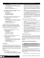
4. Installation
Prior to installing this product:
• Read the instructions carefully and completely to ensure
safe operation. Failure to follow the instructions could lead
to damage to the product or cause a hazardous condition.
• Check the ratings given on the product to make sure it is
suitable for your application.
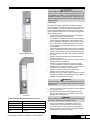
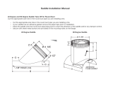
Remember to select a location that is readily accessible for
periodic inspection, cleaning, and service. The following table
indicated the minimum allowable installation clearances. The
following illustrations show some of the possible installation
congurations and where the humider should be installed.
This model must be installed on the discharge air side of the
furnace or heat-pump so that it will operate with the warmest
possible air.
Upow - Side Return
Horizontal Flow

Preferred
TM
Model PF845411/PF845412
Installation, Operation, & Maintenance Manual
5
Preferred Products
Upow - Bottom Return
Down-ow
4.1 Recommended Minimum Installation Clearance
Left 3 inches
Right 3 inches
Top 2 inches
Bottom 6 inches
Back 12 inches
!
CAUTION
This humidier should be installed by a qualied service per-
son only. Do not connect the unit to the power source until
the installation is complete. A thorough checkout of the unit
installation should be completed before operating the unit.
Failure to follow these directions may void the manufacturer’s
original warranty.
4.2 Mounting
The Preferred
TM
PF845411/PF845412 humidier should be
mounted directly to the warm air supply duct of your HVAC sys-
tem. Since warm air is required for maximum performace, do
not mount the humidier to the return side of the HVAC duct.
Certain conditions must be met to ensure proper unit operation.
Refer to the following list.
• Ensure that the duct surface is reinforced, if necessary, to
allow the unit to remain level and plumb.
• Ensure that the humidier has adequate clearance to allow
for the removal and replacement of the evaporator pad.
• When installing the humidier in an attic or above a ceiling,
a drain tray must be installed under the unit as a precau-
tionary measure to prevent water damage from occuring if
a leak develops.
• The recommended humidistat range is 30-40% relative hu-
midity. If condensation occurs on windows, the humidistat
setting must be lowered to prevent condensation damage.
• DO NOT install the humidier where freezing temperatures
may occur.
• DO NOT install the humidier where it interferes with the
furnace access panels.
• DO NOT install the humidier close to a ue pipe. Intense
heat may damage the humidier.
• DO NOT mount the humidier in the jacket of a cased
coil. It is preferable to mount the humidier immediately
downstream of the cased coil, if present. Ensure that the
humidier does not interfere with the coil ends.
• DO NOT mount the humidier in a furnace jacket.
• DO NOT install on gravity hot air systems.
• DO NOT connect a hot water supply to Preferred
TM
humidi-
ers that are equipped with water saving controls. (Model
PF845412 with Water Saving Controls).
!
IMPORTANT
The unit must be installed so that interconnection can be
made to the source of electrical supply without the use of an
extension cord.
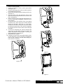
1. Tape the mounting template to the duct so that it is at and
the top edge is level.
2. Carefully remove the center of the template by tearing
along the perforated lines. Use a marker to trace on the
duct along the cutout opening.
!
WARNING
Electrical power to the furnace must be disconnected before
proceeding. Serious injury or death may result.
3. Drill the holes marked on the template. Remove the
template from the duct and carefully cut the duct along
the outside edge of the rectangle that was traced by the
marker. Remove any burrs from the cut edge of the sheet
metal taking care not to injure yourself.

Preferred
TM
Model PF845411/PF845412
Installation, Operation, & Maintenance Manual
6 Preferred Products
4. Apply the gasket material found in the accessory bag to
the duct around the rectangular cutout.
5. Lift the humidifer base into the rectangular opening so that
the plastic tabs engage the lower edge of the rectangular
opening. The tabs should be on the inside of the duct. Tilt
the upper edge of the humidier against the duct so that
the mounting holes line up with the drilled holes on the
duct. Secure the humidier with two #8 X 3/4” self-drilling-
sheet metal screws from the accessory bag.
6. Refer to the section regarding pad replacement on page
8. Complete that section before proceeding to ensure
that the internal components of the humidier are properly
aligned/installed as they may have become misaligned
during shipment. Failure to complete this task may result
in faulty operation or leaks.
7. Ensure that the humidier is level and plumb before pro-
ceeding.
4.3 Plumbing
1. Install a saddle valve and strainer (not provided) on the
nearest cold water supply pipe. (See the instructions that
accompany the saddle valve for additional details).
2. After the saddle valve and strainer are installed but before
inserting the line into the humidier supply tting, turn the
saddle valve to the open position and discharge the water
into a bucket or pan. This will allow the water to ush any
debris that may have accumulated in the line during the in-
stallation process. Once this is complete, close the saddle
valve.
3. Attach the line to the humidier by simply pushing the line
into the push-to-lock tting and pulling back slightly to seat
the line. If it becomes necessary to remove the line, press
on the release ring around where the line goes into the t-
ting to release the line and pull it out. See Figure 5 for
plumbing diagram.
4. Connect the drain hose to the drain connection tting and
run this to an open, gravity drain. The end of this line must
not be submerged in water or be trapped.
5. Turn on the saddle valve.
6. Ensure that no water is leaking from any of the ttings be-
fore proceeding.
Figure 5
4.4 Electrical
!
CAUTION
This humidier should be installed by a qualied service per-
son only in accordance with the Nation Electric Code, ANSI/
NFPA 70 and the Rules of the Canadian Electric Code, Part
I, C22.1. Do not connect the unit to the power source until
the installation is complete. A thorough checkout of the unit
installation should be completed before operating the unit.
Failure to follow these directions may void the manufacturer’s
original warranty.
The Preferred
TM
PF845411/PF845412 humidier requires a
120 VAC source of electrical power. The unit is equipped with
a line-cord so that this power source may be connected easily.
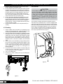
Before proceeding, ensure that interconnection of the 120 VAC
power may be accomplished without the use of an extension
cord. In order to access the wiring compartment remove the
screw as shown in Figure 6. Once the screw is removed, the
door may be opened as shown in Figure 7.
Figure 6

Preferred
TM
Model PF845411/PF845412
Installation, Operation, & Maintenance Manual
7
Preferred Products
Figure 7
4.4.1 Wiring Model PF845411(without water saving controls)
Wiring the high voltage portion of the unit:
Plug line cord into a source of 120 VAC electrical power. Pro-
vide means of overload protection as required.
VALVE
SOLENOID
HUMIDISTAT
MANUAL
SWITCH
AIR PROVING
24 VAC
R1
TRANSFORMER
120 VAC
LINE CORD
HUMIDIFIER
120 VAC
Figure 8
Wiring the low voltage portion of the unit:
Refer to Figure 8. Air proving switch (not provided) is optional.
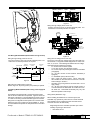
4.4.2 Wiring Model PF845412(water saving contol equipped
model)
The PF845412 is equipped with a circuit board that controls
how the fan and water valve are powered. Figure 9 shows the
main parts of the board. The wiring diagram is shown in gure
10. Refer to the wiring notes shown after Figure 10 for board
wiring/control congurations that explain how to set the board
based upon the type of system it is being installed on. These
recommendations will provide the best performance and water
savings.
LINE CORD
TERMINALS
LOW VOLTAGE
TERMINALS
DIP SWITCHES
MOTOR
CONNECTOR
RESET
BUTTON
THERMISTOR
CONNECTORS
LED
VALVE
CONNECTOR
Figure 9
Wiring the high voltage portion of the unit:
Plug line cord into a source of 120 VAC electrical power. Pro-
vide means of overload protection as required.
SOLENOID
VALVE
YEL
YEL
BLK
WHT
GRN
MOTOR
DUCT THERMISTOR
UNIT THERMISTOR
MANUAL
HUMIDISTAT
SWITCH
AIR PROVING
HUMIDISTAT
ELECTRONIC
OR
TERMINALS. SEE
FROM SYSTEM
WIRING NOTES
LINE CORD
120 VAC
TERMINALS. SEE
TO SYSTEM
WIRING NOTES
Figure 10
Wiring the low voltage portion of the unit:
The source of 24 VAC (low voltage) comes from the HVAC sys-
tem terminals. The typical terminal designators are used, such
as R, C, G, W, etc. The following list identies the low voltage
terminals and their respective connection.
• R = 24 VAC from the HVAC system
• C= 24 VAC common from the HVAC system
• Hr = 24 VAC output for powering the electronic humidistat
(if equipped)
• Hc = 24 VAC common for the electronic humidistat (if
equipped)
• H = Humidistat input (must be 24 VAC)
• W/G = Input from HVAC system. This is used when
the humidier is used with warm air furnaces. See DIP
switch settings in section 5.
• AP1/AP2 = Air proving switch is connected here. Do not
apply voltage.
• Go = 24 VAC output may be used to energize a relay or
connected back to the thermostat “G” terminal to turn on
the HVAC fan. Thermostat functionality may vary and
affect the operation of this output.
Wiring Notes (PF845412 only):
When installing the PF845412 on a furnace system, the
humidier may operate only when there is a call-for-heat OR
the humidier may be congured to start the HVAC blower
whenever there is a call-for-humidity.
Single Stage Furnace: Humidier operates upon call-for-
humidity only during a call-for-heat.
• DIP Switch #3: On

Preferred
TM
Model PF845411/PF845412
Installation, Operation, & Maintenance Manual
8 Preferred Products
is too large for the load, you may change the DIP switch
position to ON. It is not necessary in most cases.
• DIP #3 = Temperature Check - If you are installing this
humidier on a system that will have duct temperatures
regularly below 100°F, set this DIP switch to the OFF po-
sition. Typical furnace bonnet temperature is nominally
120°F.
• DIP #4 = Furnace Runs Fan/Humidier Runs Fan - In
most systems the HVAC system operates the main blow-
er. The PF845412 has a 24VAC output that may be used
to start the main blower if you would like to be able to get
some humidcation while the furnace is off.
• DIP #5 = Temperature Override - This DIP switch is fac-
tory set to OFF. In the event of a T1 thermistor failure,
this switch may be set to ON. This will allow the humidi-
er to operate temporarily with a single thermistor until a
replacement is aquired.
5.1 Preliminary Checkout and Start-up Sequence
1. Check that unit drain plumbing is properly connected and
drained.
2. Ensure that the supply plumbing is installed properly.
3. Open cold water supply and insure water is reaching the
unit. Incoming water line should be ltered.
4. Ensure that the unit’s line cord is plugged into an appro-
priate power source.
5. With the unit powered and the humidistat has a “call for
humidity”, the indicator LED (if equipped) will illuminate
Green and the unit will begin operation.
6. If at any point the indicator LED illuminates red or blinks
red/green alternating, a fault has been detected; service
will be required and the fault must be reset. Refer to the
Maintenance & Troubleshooting section.
7. Refer to the humidistat manual for “call for humidity” per-
centage settings.
5.2 Starting/Stopping the unit
In order to start and stop the unit you must only raise or lower
the humidistat setting to a point at which the contacts are closed
or open. When the humidistat contacts are closed, the unit will
start. When the humidistat contacts are open, the unit will stop.
Unplugging the line cord may not remove all sources of power
to the unit.
6. Maintenance & Troubleshooting
!
DANGER - RISK OF ELECTRIC SHOCK
Before cleaning, servicing, or parts replacement, the unit must
be disconnected from all sources of electricity.
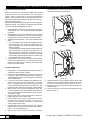
6.1 Pad Replacement
It will become necessary to replace the pad inside your Pre-
ferred
TM
PF845411/PF845412 humidier as time goes on. A
solid red LED Service indicator light may light up. This will tell
you that it is time to service your humidier. Please refer the
following procedure.
1. Adjust Humidistat to the lowest setting to ensure that
• DIP Switch #4: Off
• Air Proving Switch: Recommended but not required.
If no air proving switch is used, install a jumper across
the AP1/AP2 terminals
• Go Terminal: No Connection
• W/G Terminal: Connected to System “W”
Multi Stage/Modulating Furnace: Humidier operates upon
call-for-humidity only during a call-for-heat.
• DIP Switch #3: Off
• DIP Switch #4: Off
• Air Proving Switch: Required
• Go Terminal: No Connection
• W/G Terminal: No Connection
Single or Multi Stage Furnace: Humidier operates upon a
call-for-humidity and will start the HVAC blower.
• DIP Switch #3: Off
• DIP Switch #4: On
• Air Proving Switch: Recommended but not required.
If no air proving switch is used, install a jumper across
the AP1/AP2 terminals
• Go Terminal: Connected to System “G”
• W/G Terminal: No Connection
Although the capacity of the humidier may be reduced by
more than 40%, the PF845412 may be installed on a heat
pump system and congured to operate only when there is a
call-for-heat OR the humidier may be congured to start the
HVAC blower whenever there is a call-for-humidity.
Heat Pump System: Humidier operates upon call-for-
humidity only during a call-for-heat.
• DIP Switch #3: Off
• DIP Switch #4: Off
• Air Proving Switch: Required
• Go Terminal: No Connection
• W/G Terminal: No Connection
Heat Pump System: Humidier operates upon a call-for-
humidity and will start the HVAC blower.
• DIP Switch #3: Off
• DIP Switch #4: On
• Air Proving Switch: Recommended but not required.
If no air proving switch is used, install a jumper across
the AP1/AP2 terminals
• Go Terminal: Connected to System “G”
• W/G Terminal: No Connection
5. Operation
Once the PF845411/PF845412 is installed and ready to be start-
ed, the humidistat and DIP switches on the control board within
the humidier unit must be conrgured. The PF845411 without
the water saving controls does not have any DIP switches to
congure. You may skip to the Preliminary Checkout and Start-
up Sequence.
DIP Switches/Settings:
• DIP #1 = Bypass or Motorized (Factory Set)
• DIP #2 = High Capacity/Low Capacity - This is factory
set to High Capacity. If you determine that the humidier

Preferred
TM
Model PF845411/PF845412
Installation, Operation, & Maintenance Manual
9
Preferred Products
Figure 12
Figure 13
Figure 14
there is no call for humidity.
2. Unplug the humidier in order to remove power before
servicing the unit.
3. Close the water supply valve so that no water may ow to
the humidier during servicing.
4. Remove the screw that secures the wiring access cover.
See Figure 11.
5. Open the access cover and remove the screw on the
right side of the opening that holds the motor dome to the
base. See Figure 12.
6. With the screws removed, unplug the wiring from the mo-
tor to the circuit board (if equipped) or disconnect the 3
wire connector.
7. Lift the entire dome from the base of the unit by pulling
the bottom of the dome away from the base and then
lifting it off of the base. See Figure 13. If you discon-
nected the motor leads correctly, the motor dome should
be free from the base and you can remove it completely.
Do not hang the dome from the motor wires as damage
can result.
8. To remove the evaporator pad, push the retaining clips
and pull the top pad retainer out from the base. The
retainer and pad will come out together. The drain pan
stays inside the unit. See Figure 14.
9. Reassemble the humidier.
10. If required, reset the service timer (RED LED) by press-
ing the reset button on the circuit board (if equipped) for
three seconds. PF845412 units with water saving con-
trols include a circuit board.
Figure 11

Preferred
TM
Model PF845411/PF845412
Installation, Operation, & Maintenance Manual
10 Preferred Products
6.2 Control Board Faults & Reset
Faults are indicated by a red and green ashing LED located
on the base of the unit in the lower left corner. (See gure 9
above). There is a reset button on the control board that will
reset the unit in the event of a fault. Use the fault list below and
the troubleshooting chart to diagnose the fault and correct any
issues that may be present.
When the LED is glowing solid green, the unit is humidifying and
operating normally. The following list describes the faults that
may occur and will be displayed by the LED’s.
1. Rapid Red Blink = Terminals AP1 & AP2 for the air proving
switch did not close. The unit will not operate until airow
is present.
2. Slow Red Blink = Once the solenoid valve is energized and
humidication has begun, the controls must see a change
in termperature or the unit will not be allowed to operate.
3. Alternating Red/Green Blink = One of the thermistors has
failed.
• If T1 has failed the LED will blink Green/Red/Red with a
two second delay. The unit will not operate in this con-
dition unless DIP switch #5 is turned ON and the reset
button is pressed.
• If T2 has failed the LED with blink Green/Green/Red with
a two second delay. The unit will not operate in this con-
dition unless the T1 thermistor is relocated to act as T2
and DIP switch #5 is turned ON. Using the override DIP
switch is only recommended as a temporary solution until
the failed thermistor can be replaced.
4. Solid Red LED = This functions to remind the homeowner
to replace the evaporator pad. The unit will continue to op-
erate and the LED may be cleared by pressing the reset
button on the control board.
6.3 Motor Replacement
1. Follow steps 1-7 in the pad replacement section in order to
separate the dome from the unit base.
2. Insert a at-head screwdriver into the motor cover as shown
in Figure 15. Tilt the screwdriver up as shown in Figure 16.
This willl release the motor cover and allow you to slide it off
of the humidier dome.
3. If you have a circuit board equipped unit (PF845412), un-
plug the motor cable from the circuit board. If you have
a unit not equipped with a circuit board, unplug the white
connector to free the motor leads from the relay board. The
motor/dome will now be free from the base of the humidier.
4. With the motor cover removed, as described in step 2, dis-
connect the quick-connects from the black and white wires.
Also, remove the ground terminal from the motor by remov-
ing the ground screw.
5. Using an allen wrench, loosen the setscrew on the fan im-
peller to remove it from the motor shaft.
6. Using a nutdriver, remove the four nuts that secure the mo-
tor to the dome and remove the motor. Take care not to
misplace the nuts, washers, & grommets. These will be
used to mount the new motor.
7. Install the new motor to the dome using the nuts, washers,
& grommets that you removed from the old motor. Refer to
Figure 17 to see installation order.
8. With the new motor mounted to the dome, connect the
ground wire to the motor and reconnect the quick-connect
terminals on the black and white wires.
Figure 15
Figure 16
9. Replace the motor cover by sliding it onto the dome until it
bottoms out. Place the dome back on the base and secure
it with the screw removed previously. Refer to Figure 13.
10. Reconnect the motor cable that was disconnected as de-
scribed in step 3.
11. Close the access door on the dome and replace the screw.
Refer to Figure 12.

Preferred
TM
Model PF845411/PF845412
Installation, Operation, & Maintenance Manual
11
Preferred Products
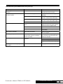
6.3 Troubleshooting Chart PF845412 (water saving units only)
Problem/Symtom Probable Cause Corrective Action
Power is applied and the LED does not
illuminate.
No issue. The LED does not illuminate unless the
humidistat terminals are closed.
Humidistat contacts are closed but the
unit will not operate.
System Calibration in progress. Wait 2 minutes for the unit to begin
operating.
Solenoid Valve is not operating Ensure that there is power supplied to
the valve. Check control board output.
Motor is not operating Ensure that there is power supplied to
the motor. Check control board output.
Circuit Board has failed/fuse is blown Replace circuit board.
Motor will not operate/turn. Motor internal thermal protective device
is open.
Remove power and allow motor to cool.
Restart unit and ensure proper operation.
If motor will not turn, replace motor.
Motor has failed Replace motor.
Fan is stuck Remove obstruction or replace fan/motor
as necessary.
LED is glowing solid RED. Service Timer has expired Replace the humidier pad and reset the
LED. See page 8.
LED displays a rapid red blink. Air proving switch did not close allowing
the unit to start. Unit will not operate if
airow is not present.
Ensure that the fan is operating and reset
the control board by pressing the reset
button for 3 seconds.
LED displays a slow red blink. No temperature change measured by
thermistors.
Ensure thermistors are connected.
Check water supply.
Verify that the evaporator pad is getting
wet.
LED displays an alternating red/green
blink pattern.
Thermisor failure. See page 9.

Preferred
TM
Model PF845411/PF845412
Installation, Operation, & Maintenance Manual
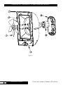
12 Preferred Products
11
10
3
13
22
12
Figure 17

Preferred
TM
Model PF845411/PF845412
Installation, Operation, & Maintenance Manual
13
Preferred Products
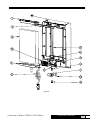
29
7
8
14
6
21
16
15
1
16
18
17
20
20
4
Figure 18

Preferred
TM
Model PF845411/PF845412
Installation, Operation, & Maintenance Manual
14 Preferred Products
29
7
9
14
6
25
19
16
15
1
16
17
2
Figure 19

Preferred
TM
Model PF845411/PF845412
Installation, Operation, & Maintenance Manual
15
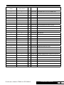
Preferred Products
PF845411 w/o circuit
board
PF845412 with water
saving controls
ITEM P/N DESCRIPTION
1 1 1 266372-001 SOLENOID VALVE, 24V, W/ CONNECTOR
1 - 2 G-217 FLUID RESTRICTOR (not shown)
1 1 3 G-110 BLADE - FAN
- 1 4 G-128 FLUID RESTRICTOR
1 - 5 63667 TRANSFORMER - 120V-24V (not shown)
1 1 6 265455-001 DRAIN TRAY
1 1 7 265456-001 FILTER RETAINER
- 1 8 265457-001 ASS'Y-DISTRIBUTION TUBE 18 HOLE
1 - 9 265457-002 ASS'Y-DISTRIBUTION TUBE 6 HOLE
1 1 10 265460-001 MAIN-SHROUD
1 1 11 266371-001 MOTOR MAIN DOME
1 1 12 265462-001 MOTOR CAP
1 1 13 265463-001 DOME ACCESS DOOR
1 1 14 265470-001 PAD - EVAPORATOR
1 1 15 265471-001P PAINT - BRACKET,SOLENOID VALVE
2 2 16 265698-001 PNEUMATIC PUSH-TO-CONNECT FITTING
1 1 17 153296-007 TUBING, 1/4" O.D. x 15" LG
- 1 18 266370-001 CONTROL BOARD, for PF845412
1 - 19 265800-001 BOARD WITH RELAY, PLATE
- 2 20 266180-001 THERMISTOR ASSEMBLY, APPROX. 9"
- 1 21 265628-001 POWER CORD, 6'
1 1 22 265807-001 MOTOR ASS'Y
- 1 23 265846-001 WIRING HARNESS ASSY, PF845412 (not shown)
1 - 24 265846-003 WIRING HARNESS ASSY, PF845411 (not shown)
1 - 25 265847-001 POWER CORD ASS'Y
2 - 26 265849-001 MOTORIZED RELAY/TERM. WIRE (not shown)
- 1 27 265160-002 HUMIDISTAT, ELECTRONIC (not shown)
1 - 28 265160-001 HUMIDISTAT, MECHANICAL (not shown)
1 1 29 266257-001 MAIN BASE PF845411

Form No. 265817-004 rev. 10182012 © 2011. All Rights Reserved.
Preferred Products
4744 Island Ford Rd. | Randleman, NC 27317
www.askpreferred.com
-
 1
1
-
 2
2
-
 3
3
-
 4
4
-
 5
5
-
 6
6
-
 7
7
-
 8
8
-
 9
9
-
 10
10
-
 11
11
-
 12
12
-
 13
13
-
 14
14
-
 15
15
-
 16
16


Preferred PF845411 Installation, Operation & Maintenance Manual
- Type
- Installation, Operation & Maintenance Manual
- This manual is also suitable for
Ask a question and I''ll find the answer in the document
Finding information in a document is now easier with AI
Other documents
-
 Skuttle 86 Owner's manual
-
 Skuttle Indoor Air Quality Products SK0-0055-001 User manual
-
 Speedi-Products SM-SDL45 08 Operating instructions
-
Bryant HUMBBLBP2018-A User manual
-
FIELD CONTROLS S2020 Installation guide
-
Carrier HUMXXSFP1012 Installation Instructions Manual
-
 EWC Controls S2020 User manual
-
Aprilaire 800 Installation guide
-
Trion CM200 Flow-Through Humidifier User manual
-


