Page is loading ...

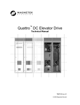
Quattro™ DC
Quattro™ DC Elevator Drive
Technical Manual
To properly use the product, read this manual thoroughly and retain for easy reference, inspection,
and maintenance. Ensure that the end user receives this manual.
TM7337 rev 23
© Magnetek Elevator 2018

WARRANTY Standard products manufactured by the Company are warranted to be free from
defects in workmanship and material for a period of one year from the date of
shipment, and any products which are defective in workmanship or material will be
repaired or replaced, at the Company’s option, at no charge to the Buyer. Final
determination as to whether a product is actually defective rests with the Company.
The obligation of the Company hereunder shall be limited solely to repair or replace,
at the Company’s discretion, products that fall within the foregoing limitations, and
shall be conditioned upon receipt by the Company of written notice of any alleged
defects or deficiency promptly after discovery and within the warranty period, and in
the case of components or units purchased by the Company, the obligation of the
Company shall not exceed the settlement that the Company is able to obtain from the
supplier thereof. No products shall be returned to the Company without its prior
consent. Products which the company consents to have returned shall be shipped
prepaid f.o.b. the Company factory. The Company cannot assume responsibility or
accept invoices for unauthorized repairs to its components, even though defective.
The life of the products the Company depends, to a large extent, upon type of usage
thereof and THE COMPANY MAKES NO WARRANTY AS TO FITNESS OF ITS
PRODUCTS FOR THE SPECIFIC APPLICATIONS BY THE BUYER NOR AS TO
PERIOD OF SERVICE UNLESS THE COMPANY SPECIFICALLY AGREES
OTHERWISE IN WRITING AFTER PROPOSED USAGE HAS BEEN MADE KNOWN
TO IT.
This warranty does not apply to experimental products for which no warranty is made
or given and Buyer waives any claim thereto.
THE FOREGOING WARRANTY IS EXCLUSIVE AND IN LIEU OF ALL OTHER
WARRANTIES, EXPRESSED OR IMPLIED, INCLUDING, BUT LIMITED TO, ANY
WARRANTY OF MECHANTIBILITY OR OF FITNESS FOR A PARTICULAR
PURPOSE AND BUYER HEREBY WAIVES ANY AND ALL CLAIMS THEREFORE.
LIMITATIONS IN NO EVENT SHALL MAGNETEK BE LIABLE FOR LOSS OF PROFIT,
OF LIABILITY INDIRECT, CONSEQUENTIAL OR INCIDENTAL DAMAGES WHETHER
ARISING OUT OF WARRANTY, BREACH OF CONTRACT OR TORT.
QUATTRO is a trademark of Magnetek, Inc.
All rights reserved. No part of this publication may be reproduced or used in any form or by any means - graphic, electronic, or
mechanical including photocopying, recording, taping, or information storage and retrieval systems - without written permission
of the publisher.
2018 Magnetek, Inc.

1
Quattro™ Startup guide
1. Prior to applying any voltage to the drive complete the following steps.
2. Record the following motor data;
a. Rated Motor Volts, Amps, Field amps forcing, Field amps running
b. Rated motor RPM, Rated encoder PPR, Elevator speed (ft/min, m/sec, mm/sec)
c. If using a friction wheel, find the ratio between wheel and the surface it is riding on
3. Disconnect the motor armature wires and the field wires from the drive;
a. Using a megger at 500 – 1000V, a good reading is 2Mohms or larger.
i. Armature
1. Check A1 to ground
2. Check A2 to ground
3. If a breakdown is detected this must be addressed before
proceeding.
ii. Field
1. Check F1 to ground
2. Check F2 to ground
3. If a breakdown is detected this must be addressed before
proceeding.
iii. Armature - Field
1. Check A1 /2 to F1 / 2
2. If a breakdown is detected this must be addressed before proceeding.
b. Measure the total field resistance (F1 – F2) with a DVOM, record this number.
c. Measure the resistance of each individual field coil.
d. Perform an AC drop test on the field coils.
i. Apply 120 / 240VAC to F1 and F2, measure the AC voltage on each coil.
1. These numbers should be similar for each coil.
4. Is Quattro configured with the standard field module or the alternate low voltage version?
a. High voltage module generates motor field current from 1 – 40A. This module will
work for all cases and has no additional switches or jumpers to set.
b. Low voltage module is design for to separate ranges; 1- 20A and 20 -40A. The
hardware requires two separate hardware setups to set the range. This module can
be identified by the addition of a transformer plugged in at location J3, for the low
range this must be located in the ‘A’ position and the high range would be the ‘B’. In
addition JP1 jumper must be installed in the ‘A’ location for low and ‘B’ for the high
range.
If using the low voltage supply, this quick check should be completed to verify it will work on
this specific motor;
Calculate both Vbus (DC bus voltage) and Vf (voltage required on the motor field to reach full
field amps).
Vbus = (Vin x SQRT 2) + DC Bus Voltage Boost (A5), where Vin is the three phase AC
voltage applied to the Quattro, if an auto-transformer is used then this would be measured at
the secondary, SQRT 2 = 1.41, DC Bus Voltage Boost (A5) is defaulted to 30 and has the
range of 15 – 75.
Vf = Full FLD Current (A6) x Field resistance, where the Full FLD Current is the maximum DC
current which will be applied to the motor fields, field resistance is obtained by disconnecting
the motor field wires at TB3 – 1 and TB3 -2 and measuring the resistance. A typical number
for this would be 5 – 100 ohms.
These are the two condition which are being tested;

a. Full FLD Current (A6) less than or equal to 20
a. Vbus / 2 must be greater than or equal to (Vf x 1.5)
b. Full FLD Current (A6) greater than 20
a. Vbus / 4 must be greater than or equal to (Vf x 1.5)
If either of these conditions are not true then the standard field module must be used
5. Input voltage requirements.
These are the two equations to calculate to determine the minimum AC voltage applied to the
drive based on the conditions;
‐ Rated drive amps is the current rating of the Quattro
DC drive 125, 150, 200, 250, 300.
‐ Full Load Motor Volts is the required voltage to run at
contract speed up at full load. If this isn’t know use the
motor nameplate volts.
a. V L-L = (((Full Load Motor Voltage X 1.3) – 75) / 1.41)
Equation 1. Nominal Line to Line voltage
b. V L-L = ((Rated motor current X Full Load Motor voltage x 0.92) / rated
drive amps)
Equation 2. Nominal Line to Line voltage
The drive will require the larger of the values from Equation 1 and 2. This determines
minimum voltage required to operate that motor. If the actual voltage is less than this calculation, then
it would be required that the voltage be stepped up. Magnetek has optional Auto transformers
specifically designed for this purpose and will fit within the Quattro drive enclosure. If the actual
voltage applied to the Quattro exceeds 1.5 x rated motor voltage, then it would be recommended that
the voltage be stepped down to closer to 1 to 1.1 times rated motor voltage. The chart shown below
provides a method to select an auto transformer.
6. Open the fuse holders in the drive labeled F1, 2, 3, 4
7. Apply three phase power to the drive, measure the 230V control power on the line side of F1,
F2. This should be between 220 and 240Vac.
8. Turn off the three phase power and close the F1, F2 fuse holders. Re-apply the three phase
power. Locate the LV Power Distribution PCB (A10), verify the low voltage DC levels;

3
a. Check TP1 +5V, TP3 +15V, TP4 -15V, Reference TP2 COM, TP5 +24V, reference
TP6 C_24V.
9. Verify all of the drive parameters are set according to the controller manufacturers
recommendations.
10. Close the F3, F4 fuse holders, and clip the meter leads on those same points. Set the meter
on DC voltage. Push the PCM relay in for about 1s (damage will occur if held in longer!!),
then release, the meter should read the line voltage x 1.41. Dropping slowly is normal, quick
is not a good condition.
11. Once, the drive has passed all of the steps, the drive is ready to run the auto tune. To start
the process, go to the selection ‘A4 AUTO TUNE MOTOR’. If it completes with no faults, then
go into the A4 menu and select the gain selection method ‘Use self-tune’, the drive is ready to
run the elevator.
12. Next, the field current can be adjusted.
a. In the A6 menu, there is forcing current, running current and standing current. The
forcing current may be on the motor N.P. or perhaps the field voltage is available (FFA
= FFV / Field R). After that step is complete, run the elevator from bottom to top at
100% contract speed, adjust the weak field amps until the armature volts measure
nameplate. Standing field can be set to 10 – 25% of the forcing current.
13. At balanced load run the elevator from bottom to top, then top to bottom. Look in the D1 menu
and locate the Estimated Inertia, enter this as the new inertia in the A1 menu.

Table of Contents
Introduction ............................................................................................................. 16
Drive Ratings and Specifications ....................................................................................................... 16
Software Operating Features ............................................................................................................. 17
Drive Model Numbers ........................................................................................................................ 17
Part Number Definition ........................................................................................... 18
QDC AAA-1BCD-EE ................................................................................................ 18
Quattro startup guide ............................................................................................. 19
Initial Inspection ................................................................................................................................. 19
Advanced output filter ........................................................................................................................ 21
Grounding considerations .................................................................................................................. 21
Initial adjustments after power up ...................................................................................................... 22
Interconnections ..................................................................................................... 24
Drive Sequencing .................................................................................................... 31
NORMAL operating sequence ........................................................................................................... 31
ABNORMAL operating sequence ...................................................................................................... 32
Quattro Pre-Charge ........................................................................................................................... 32
Drive Operation and Feature Overview ................................................................. 33
Analog Velocity Follower ................................................................................................................... 33
Preset Speed & Profile Generator ..................................................................................................... 33
Serial Link Follower ............................................................................................................................ 33
Pre-Torque ......................................................................................................................................... 33
Torque Feed Forward ........................................................................................................................ 33
Torque/Current Ramp-Down ............................................................................................................. 33
Motor Field Current Control and Field weakening ............................................................................. 33
DSPR ................................................................................................................................................. 34
Over-Speed Test ................................................................................................................................ 34
Fault & Alarm Reset ........................................................................................................................... 34
Electronic Motor Over-Load ............................................................................................................... 34
Armature Voltage Feedback .............................................................................................................. 34
EN81-1 Single Contactor .................................................................................................................. 35
Parameters .............................................................................................................. 36
Parameter Introduction ...................................................................................................................... 36
Menu Navigation ................................................................................................................................ 37
Parameter Tree .................................................................................................................................. 39
Adjust A0 menu ....................................................................................................... 41
Drive A1 submenu ............................................................................................................................. 41
S-Curves A2 submenu ....................................................................................................................... 51
Multistep Ref A3 submenu ................................................................................................................. 53
Motor Side Power Convert A4 submenu ........................................................................................... 55
Line Side Power Converter A5 submenu........................................................................................... 57

5
Motor Parameters A6 submenu ......................................................................................................... 59
Configure C0 menu ................................................................................................. 64
User Switches C1 submenu .............................................................................................................. 64
Logic Inputs C2 submenu .................................................................................................................. 78
Logic Outputs C3 submenu ............................................................................................................... 81
Analog Outputs C4 submenu ............................................................................................................. 83
Display D0 menu ..................................................................................................... 84
Elevator Data D1 submenu ................................................................................................................ 84
MS Power Data D2 submenu ............................................................................................................ 87
LS Power Data D3 submenu ............................................................................................................. 88
Utility U0 menu ........................................................................................................ 89
Fault F0 menu .......................................................................................................... 95
Maintenance ............................................................................................................ 97
Maintenance Overview ...................................................................................................................... 97
Drive Servicing ................................................................................................................................... 97
Troubleshooting ...................................................................................................... 98
Appendix ................................................................................................................ 122
Auto Tune Procedure ....................................................................................................................... 122
................................................................................................................................ 122
Inertia Calculations .......................................................................................................................... 124
Anti-Rollback .................................................................................................................................... 125
EMC Compliance ............................................................................................................................. 128
Encoder Cable Clamps .................................................................................................................... 128
Testpoints (Main Control Board – Power Supplies) ......................................................................... 129
Testpoints (Product Interface Board – Power Supplies) .................................................................. 130
Testpoints (Product Interface Board – Other) .................................................................................. 131
Testpoints (Product Interface Board - LED definitions) ................................................................... 132
Testpoints (Power Distribution Board – Power Supplies) ................................................................ 133
Testpoints (Gate Drive Board – LED definitions) ............................................................................. 134
Testpoints (Customer Interface Board – Power Supplies) .............................................................. 136
Testpoints (Customer Interface Board – Other) .............................................................................. 137
Control Power Consumption ............................................................................................................ 138
Watts Loss ....................................................................................................................................... 138
Input / Output Ratings ...................................................................................................................... 138
Wire Terminal Specs ........................................................................................................................ 139
Note: Additional ground terminal lugs are located at the top of the drive on right side of the chassis.
These lugs will accommodate ground wires in the range of #6-350MCM (10-175mm^2) .............. 139
Dimensions / Weights Standard ...................................................................................................... 141
Dimensions / Weights with Top Hat ................................................................................................. 142
Component Locations ...................................................................................................................... 149
Low Voltage Field Module ............................................................................................................... 154
Input Voltage Requirements ............................................................................................................ 156
Spare Parts Quattro DC Drive ......................................................................................................... 160
Index ....................................................................................................................... 171

6
Sub
menu
Parameter Units Range Default
Site
Setting
A1 Drive A1 Submenu – See Drive A1 submenu on page 41.
A1 CONTRACT CAR SPD
fpm 0.0 – 1500.0 100.0
m/s 0.000 – 8.000 2.000
A1 CONTRACT MTR SPD RPM 30.0 – 3000.0 50.0
A1 RESPONSE rad/sec 1.0 – 20.0 5.0
A1 INERTIA sec 0.25 – 10.00 2.00
A1 INNER LOOP XOVER rad/sec 0.1 – 20.0 2.0
A1 CURRENT LIMIT % 0.0 – 300.0 250.0
A1 GAIN REDUCE MULT % 10 – 100 100
A1 GAIN CHNG LEVEL % of rated spd 0.0 – 100.0 100.0
A1 TACH FILTER BW rad/sec 1 – 100 100
A1 TACH RATE GAIN none 0.0 – 30.0 0.0
A1 SPD PHASE MARGIN degrees 45 – 90 80
A1 RAMPED STOP TIME sec 0.00 – 2.50 0.20
A1 CONTACT FLT TIME sec 0.10 – 5.00 0.50
A1 BRAKE PICK TIME sec 0.00 – 5.00 1.00
A1 BRAKE HOLD TIME sec 0.00 – 5.00 0.50
A1 OVERSPEED LEVEL % of contract spd 90.0 – 150.0 115.0
A1 OVERSPEED TIME sec 0.00 – 9.99 0.10
A1 OVERSPEED MULT % 100.0 – 150.0 125.0
A1 ENCODER PULSES PPR 600 – 20000 5000
A1 ENC RATIO MULT none 0.001 – 32.000 1.000
A1 SPD DEV LO LEVEL % of contract spd 0.1 – 20.0 10.0
A1 SPD DEV TIME sec 0.00 – 9.99 0.50
A1 SPD DEV HI LEVEL % of contract spd 0.0 – 99.9 10.0
A1 SPD COMMAND BIAS volts -6.00 – +6.00 0.00
A1 SPD COMMAND MULT none 0.90 – 5.00 1.00
A1 EXT TORQUE BIAS volts -6.00 – +6.00 0.00
A1 EXT TORQUE MULT none -10.00 – +10.00 1.00
A1 PRE TORQUE TIME sec 0.00 –10.00 0.00
A1 ZERO SPEED LEVEL % of contract spd 0.00 – 99.99 1.00
A1 ZERO SPEED TIME sec 0.00 – 9.99 0.10
A1 UP/DWN THRESHOLD % of contract spd 0.00 – 9.99 1.00
A1 ANA 1 OUT OFFSET % -99.9 – +99.9 0.0
A1 ANA 2 OUT OFFSET % -99.9 – +99.9 0.0
A1 ANA 1 OUT GAIN none 0.0 – 10.0 1.0
A1 ANA 2 OUT GAIN none 0.0 – 10.0 1.0
A1 FLT RESET DELAY sec 0 – 120 5
A1 FLT RESETS/HOUR faults 0 – 10 3
A1 UP TO SPD. LEVEL % of contract spd 0.00 – 110.00 90.00
A1 RUN DELAY TIMER sec 0.00 – 0.99 0.00
A1 AB ZERO SPD LEV % 0.00 – 2.00 1.00
A1 AB OFF DELAY sec 0.00 – 9.99 0.00
A1 CONTACTOR DO DLY sec 0.00 – 5.00 0.00
A1 TRQ LIM MSG DLY sec 0.00 – 10.00 0.50
A1 ARB MODE none 0 - 2 0
A1 ARB BANDWIDTH RAD 1.00 – 15.00 6.00
A1 ARB DAMPING none 0.01 – 20.00 2.00
A1
ARB SPEED
THRESHOLD
none 0.00 – 10.00 0.00
A1 NOTCH FILTER FRQ Hz 5 – 60 20
A1 NOTCH FILT DEPTH % 0 – 100 0
A1 STNDBY FLD TIME sec 0 – 999 5

Quattro DC Quick Parameter Reference
7
Sub
menu
Parameter Units Range Default
Site
Setting
A1 DSPR TIME min 0 – 546 10
A1 FULL FIELD FLT TIME min 0 – 99 1
A1 SER2 INSP SPD
ft/s2 0 – 100 30
m/s2
0
–
0.500
0.150
A1 SER2 RS CRP SPD
ft/s2 0 – 300 10
m/s2 0 – 1.540 0.050
A1 SER2 RES CRP TIME Sec 0 – 200.0 180
A1 SER2 FLT TOL Sec 0 – 2.00 0.5
A2 S-Curves A2 Submenu – See S-Curves A2 submenu on page 51.
A2 ACCEL RATE 0
ft/s
2
0.00 – 7.99 7.99
m/s
2
0.000 – 3.999 2.000
A2 DECEL RATE 0
ft/s
2
0.00 – 7.99 7.99
m/s
2
0.000 – 3.999 2.000
A2 ACCEL JERK IN 0
ft/s
3
0.0 – 29.9 0.0
m/s
3
0.00 – 9.99 0.00
A2 ACCEL JERK OUT 0
ft/s
3
0.0 – 29.9 0.0
m/s
3
0.00 – 9.99 0.00
A2 DECEL JERK IN 0
ft/s
3
0.0 – 29.9 0.0
m/s
3
0.00 – 9.99 0.00
A2 DECEL JERK OUT 0
ft/s
3
0.0 – 29.9 0.0
m/s
3
0.00 – 9.99 0.00
A2 ACCEL RATE 1
ft/s
2
0.00 – 7.99 7.00
m/s
2
0.000 – 3.999 0.090
A2 DECEL RATE 1
ft/s
2
0.00 – 7.99 3.00
m/s
2
0.000 – 3.999 0.090
A2 ACCEL JERK IN 1
ft/s
3
0.0 – 29.9 8.0
m/s
3
0.00 – 9.99 2.40
A2 ACCEL JERK OUT 1
ft/s
3
0.0 – 29.9 8.0
m/s
3
0.00 – 9.99 2.40
A2 DECEL JERK IN 1
ft/s
3
0.0 – 29.9 8.0
m/s
3
0.00 – 9.99 2.40
A2 DECEL JERK OUT 1
ft/s
3
0.0 – 29.9 8.0
m/s
3
0.00 – 9.99 2.40
A2 ACCEL RATE 2
ft/s
2
0.00 – 7.99 3.00
m/s
2
0.000 – 3.999 0.090
A2 DECEL RATE 2
ft/s
2
0.00 – 7.99 3.00
m/s
2
0.000 – 3.999 0.090
A2 ACCEL JERK IN 2
ft/s
3
0.0 – 29.9 8.0
m/s
3
0.00 – 9.99 2.40
A2 ACCEL JERK OUT 2
ft/s
3
0.0 – 29.9 8.0
m/s
3
0.00 – 9.99 2.40
A2 DECEL JERK IN 2
ft/s
3
0.0 – 29.9 8.0
m/s
3
0.00 – 9.99 2.40
A2 DECEL JERK OUT 2
ft/s
3
0.0 – 29.9 8.0
m/s
3
0.00 – 9.99 2.40
A2 ACCEL RATE 3
ft/s
2
0.00 – 7.99 3.00
m/s
2
0.000 – 3.999 0.090
A2 DECEL RATE 3
ft/s
2
0.00 – 7.99 3.00
m/s
2
0.000 – 3.999 0.090
A2 ACCEL JERK IN 3
ft/s
3
0.0 – 29.9 8.0
m/s
3
0.00 – 9.99 2.40
A2 ACCEL JERK OUT 3
ft/s
3
0.0 – 29.9 8.0
m/s
3
0.00 – 9.99 2.40
A2
DECEL JERK IN 3
ft/s
3
0.0 – 29.9 8.0
m/s
3
0.00 – 9.99 2.40

Quattro DC Quick Parameter Reference
8
Sub
menu
Parameter Units Range Default
Site
Setting
A2 DECEL JERK OUT 3
ft/s
3
0.0 – 29.9 8.0
m/s
3
0.00 – 9.99 2.40
A2
ACCEL RATE 4
ft/s
3
0.0 – 7.99 5
m/s
3
0.000 – 3.999 1.52
A2
DECEL RATE 4
ft/s
3
0.0 – 7.99 5
m/s
3
0.000 – 3.999 1.52
A2 ACCEL JERK IN 4
ft/s
3
0.0 – 29.9 0
m/s
3
0.00 – 9.99 0
A2 ACCEL JERK OUT 4
ft/s
3
0.0 – 29.9 0
m/s
3
0.00 – 9.99 0
A2 DECEL JERK IN 4
ft/s
3
0.0 – 29.9 0
m/s
3
0.00 – 9.99 0
A2 DECEL JERK OUT 4
ft/s
3
0.0 – 29.9 0
m/s
3
0.00 – 9.99 0
A3 Multistep Ref A3 Submenu – See Multistep Ref A3 submenu on page 53.
A3 SPEED COMMAND 1
ft/min
-3000.0 – +3000.0 0.0
m/sec
-16.000 – +16.000 0.000
A3 SPEED COMMAND 2
ft/min
-3000.0 – +3000.0 0.0
m/sec
-16.000 – +16.000 0.000
A3 SPEED COMMAND 3
ft/min
-3000.0 – +3000.0 0.0
m/sec
-16.000 – +16.000 0.000
A3 SPEED COMMAND 4
ft/min
-3000.0 – +3000.0 0.0
m/sec
-16.000 – +16.000 0.000
A3 SPEED COMMAND 5
ft/min
-3000.0 – +3000.0 0.0
m/sec
-16.000 – +16.000 0.000
A3 SPEED COMMAND 6
ft/min
-3000.0 – +3000.0 0.0
m/sec
-16.000 – +16.000 0.000
A3 SPEED COMMAND 7
ft/min
-3000.0 – +3000.0 0.0
m/sec
-16.000 – +16.000 0.000
A3 SPEED COMMAND 8
ft/min
-3000.0 – +3000.0 0.0
m/sec
-16.000 – +16.000 0.000
A3 SPEED COMMAND 9
ft/min
-3000.0 – +3000.0 0.0
m/sec
-16.000 – +16.000 0.000
A3 SPEED COMMAND 10
ft/min
-3000.0 – +3000.0 0.0
m/sec
-16.000 – +16.000 0.000
A3 SPEED COMMAND 11
ft/min
-3000.0 – +3000.0 0.0
m/sec
-16.000 – +16.000 0.000
A3 SPEED COMMAND 12
ft/min
-3000.0 – +3000.0 0.0
m/sec
-16.000 – +16.000 0.000
A3 SPEED COMMAND 13
ft/min
-3000.0 – +3000.0 0.0
m/sec
-16.000 – +16.000 0.000
A3 ft/min
-3000.0 – +3000.0 0.0

Quattro DC Quick Parameter Reference
9
Sub
menu
Parameter Units Range Default
Site
Setting
SPEED COMMAND 14 m/sec
-16.000 – +16.000 0.000
A3 SPEED COMMAND 15
ft/min
-3000.0 – +3000.0 0.0
m/sec
-16.000 – +16.000 0.000

Quattro DC Quick Parameter Reference
10
Sub
menu
Parameter Units Range Default
Site
Setting
A4 Motor Side Power Convert A4 Submenu – See Motor Side Power Convert on page 55.
A4 ARM INDUCTANCE mH
0.01 – 327.67
10.00
A4 ARM RESISTANCE ohm
0.0001 – 2.9999
0.1000
A4 MOTOR FIELD RES ohm
0.0 – 3276.7
9.0
A4 MOTOR FIELD TC sec
0.000 – 32.767
0.607
A4 AUTO TUNE MOTOR none
Start Autotune?
-
A4 GAIN SELECTION none
manual
use saved par
use self-tune
MANUAL
A4 GAIN BANDWIDTH A rad/sec
100 – 2000
500
A4 GAIN BANDWIDTH F rad/sec
1 – 40
5
A4 SPD MODEFILT BW rad/sec
5 – 110
100
A4 PWM FREQUENCY kHz
2.5 – 16.0
6.0
A4 UV ALARM LEVEL %
80 – 99
90
A4 UV FAULT LEVEL %
50 – 99
80
A4 FLD CARRIER FRQ kHz
3 – 40
3
A5 Line Side Power converter A5 Submenu – See Line Side Power Converter on page 57.
A5 Id REG PROP GAIN none 0 – 9.99 0.30
A5 Id REG INTGRL GAIN none
0 – 999
10
A5 Iq REG PROP GAIN none
0.00 – 9.99
0.30
A5 Iq REG INTGRL GAIN none
0 – 999
40
A5 DC BUS REG P GAIN none
0.00 – 9.99
3.00
A5 DC BUS REG I GAIN none
0 – 999
40
A5 INPUT L-L VOLTS volts
150 – 480
200
A5 INITIAL L FREQ Hz
50 – 60
55
A5 DC BUS V BOOST volts
15 – 75
30
A5 SW BUS OV LEVEL volts
100 – 850
850
A5 BUS VREF SOURCE none
track line v
trk vin param
TRACK LINE V
A5 PLL FILTER FC Hz
20.0 – 150.0
40.0
A5 POLE FILTER kHz
0.1 – 3.0
2.2
A5 PRE CHGE THRESH none
1 – 60
28
A5 LS PWM FREQUENCY kHz
8.0 – 12.0
10.0

Quattro DC Quick Parameter Reference
11
Sub
menu
Parameter Units Range Default
Site
Setting
A6
Motor A6 Submenu – See Motor Parameters A6 submenu on page 59.
A6 MOTOR ID None - -
A6 RATED MOTOR CURR amps 1.0 – 400.0 0.0
A6 ARMATURE VOLTAGE volts 55 – 600 0
A6 FULL FLD CURRENT amps 1.0 – 40.0 0.0
A6 WEAK FLD CURRENT amps 1.0 – 40.0 0.0
A6 STANDBY FIELD amps 0.0 – 40.0 0.0
A6 FLUX CONFIRM LEV % 25.0 – 99.0 85.0
A6 ARMATURE IR DROP % 0.0 – 25.0 0.0
A6 TACH VOLT SENSE % 0.1 – 60.0 25.0
A6 TACH SPEED SENSE % 0.1 – 40.0 5.0
A6 OVLD START LEVEL % 100 – 150 110
A6 OVLD TIME OUT sec 5.0 – 120.0 60.0
A6 SAVE MEAS ARM L mH 0.00 – 327.67 0.00
A6 SAVE IR DROP % 0.0 – 3276.7 0.0
A6 SAVE MEAS ARM R ohm 0.0000 – 3.2767 0.0000
A6 SAVE FIELD RES ohm 0.0 – 3276.7 0.00
A6 SAVE FIELD TC sec 0.000 – 32.767 0.000
C1 User Switches C1 Submenu – See User Switches C1 submenu on page 64.
C1 SPD COMMAND SRC
none
serial
multi-step
ser mult step
analog input
MULTI-STEP
C1 RUN COMMAND SRC
none
external tb
serial
serial+extrn
EXTERNAL TB
C1 FIELD ENA SOURCE
none
external tb
serial
enable on run
2-bit serial
ENABLE ON RUN
C1 HI/LO GAIN SRC
none
internal
external tb
serial
INTERNAL
C1 SPEED REG TYPE
none
elev spd reg
pi speed reg
external reg
cemf reg
ELEV SPD REG
C1 MOTOR ROTATION none
forward
reverse
FORWARD
C1 ENCODER CONNECT
none
forward
reverse
FORWARD
C1 SPD REF RELEASE
none
reg release
brake picked
REG RELEASE
C1 CONT CONFIRM SRC none external tb EXTERNAL TB fixed
C1 TACH FILTER
none
Off
On
OFF
C1 PreTorque SOURCE
none
none
analog input
serial
NONE
C1 PreTorque LATCH
none
latched
not latched
NOT LATCHED
C1 PTorq LATCH CLCK
none
external tb
serial
EXTERNAL TB
C1 OVERSPD TEST SRC
none
external tb
serial
EXTERNAL TB

Quattro DC Quick Parameter Reference
12
Sub
menu
Parameter Units Range Default
Site
Setting
C1 User switches C1 Submenu continued …
C1 FAULT RESET SRC none
external tb
serial
automatic
EXTERNAL TB
C1 BRAKE PICK SRC none
internal
serial
INTERNAL
C1 BRAKE PICK CNFM
none
none
external tb
internal time
on speed cmd
NONE
C1 BRAKE HOLD SRC none
internal
serial
INTERNAL
C1 RAMPED STOP SEL none
none
ramp on stop
NONE
C1 RAMP DOWN EN SRC none
external tb
run logic
serial
EXTERNAL TB
C1 BRK PICK FLT ENA
none
disable
enable
DISABLE
C1 BRK HOLD FLT ENA none
disable
enable
DISABLE
C1 EXT TORQ CMD SRC
none
none
serial
analog input
NONE
C1 DIR CONFIRM
none
disabled
enabled
DISABLED
C1 S-CURVE ABORT
none
disabled
enabled
DISABLED
C1 PRIORITY MESSAGE none
disable
enable
ENABLE
C1 STOPPING MODE
none
immediate
ramp to stop
IMMEDIATE
C1 AUTO STOP
none
enable
disable
DISABLE
C1 DSPR ENABLE
none
disable
enable
DISABLE
C1 ARB SELECT
none
disable
enable
DISABLE
C1 SERIAL MODE none
none
mode 1
mode 2
mode 2 Test
NONE
C1 SER2 FLT MODE none
immediate
run remove
rescue
IMMEDIATE
C1 NTSD Mode none
external
1 threshold
2 thresholds
3 thresholds
EXTERNAL
C1
C1 DSPR ENABLE none
disable
enable
DISABLE

Quattro DC Quick Parameter Reference
13
Sub
menu
Parameter Units Range Default
Site
Setting
C2
Logic Inputs C2 Submenu – See Logic Inputs C2 submenu on page 78.
C2 N.C. INPUTS
none Hex Number
0X01
C2
LOGIC INPUT 1 TB1(1)
contact cfirm
ctr pwr sense
drive enable
extrn fault 1
extrn fault 2
extrn fault 3
extrn /flt 4
fault reset
field enable
low gain sel
mech brk hold
mech brk pick
no function
ospd test src
ntsd input1
ntsd input 2
pre-trq latch
run
run 2
run down
run up
s-curve sel 0
s-curve sel 1
ser2 insp ena
step ref b0
step ref b1
step ref b2
step ref b3
trq ramp down
up/dwn
CONTACT CFIRM
fixed
LOGIC INPUT 2 TB1(2) CTR PWR SENSE
fixed
LOGIC INPUT 3 TB1(3)
LOGIC INPUT 4 TB1(4)
LOGIC INPUT 5 TB1(5)
LOGIC INPUT 6 TB1(6)
LOGIC INPUT 7 TB1(7)
LOGIC INPUT 8 TB1(8)
LOGIC INPUT 9 TB1(9)
C3
Logic Outputs C3 Submenu – See Logic Outputs C3 submenu on page 70
LOGIC OUTPUT 1
TB1(25
alarm
alarm+flt
auto brake
b. ena status
brake hold
brake pick
brk hold flt
brk pick flt
car going dwn
car going up
charge fault
close contact
contactor flt
curr reg flt
drv overload
encoder flt
fault
flux confirm
ground fault
in low gain
motor trq lim
mtr overload
no faults
no function
not alarm
ntsd Active
over curr flt
overspeed flt
overtemp flt
overvolt flt
ovrtemp alarm
phase fault
ramp down ena
ready 2 start
ready to run
regen trq lim
run commanded
run confirm
speed dev
speed dev low
speed ref rls
speed reg rls
undervolt flt
up to speed
uv alarm
zero speed
CLOSE
CONTACT
LOGIC OUTPUT 2
TB1(26)
RUN
COMMANDED
LOGIC OUTPUT 3
TB1(27)
MTR OVERLOAD
LOGIC OUTPUT 4
TB1(28)
ENCODER FLT
LOGIC OUTPUT 5
TB1(29)
FAULT
LOGIC OUTPUT 6
TB1(30)
SPEED REG
RLS
LOGIC OUTPUT 7
TB1(31)
SPEED REG
RLS
SSR1 TB1(21/22) NO FUNCTION
SSR2 TB1(23/24) NO FUNCTION
RELAY COIL 1
TB2(1/3/5)
NO FUNCTION
RELAY COIL 2
TB2(8/10/12)
NO FUNCTION
C4
Analog Outputs C4 Submenu – See analog Outputs C4 submenu on page 72
C4 ANA OUT 1 TB1-12
analog addr2
analog addr3
arb state
arm current
arm voltage
pretorque ref
motor mode
spd rg tq cmd
speed command
speed error
SPEED REF

Quattro DC Quick Parameter Reference
14
Sub
menu
Parameter Units Range Default
Site
Setting
C4 ANA OUT 2 TB1-13
aux torq cmd
bus voltage
est motor spd
field current
iarm error
ls pwr input
speed feedbk
speed ref
tach rate cmd
tach speed
torque ref
- drive overload
SPEED FEEDBK

Quattro DC Quick Parameter Reference
15
Menu Parameter Unit
D1 Elevator Data Submenu
D1 Speed Command ft/min or m/sec
D1 Speed Reference ft/min or m/sec
D1 Speed Feedback ft/min or m/sec
D1 Motor Speed RPM
D1 Speed Error ft/min or m/sec
D1 Pre-Torque Ref % of rated torque
D1 Pre-Torq Last % of rated torque
D1 Ext-Torque Cmd % of rated current
D1 Spd Reg Torq Cmd % of rated torque
D1 Tach Rate Cmd % of rated torque
D1 Aux Torque Cmd % of rated torque
D1 Est Inertia Seconds
D1 Rx Com Status 1 = true; 0 = false
D1 RX Error Count Counts
D1 Logic Outputs 1 = true; 0 = false
D1 Logic Inputs 1 = true; 0 = false
D1 Rx Logic Input 1 = true; 0 = false
D1 NTSD 1 Spd Fdbk ft/min or m/sec
D1 NTSD 2 Spd Fdbk ft/min or m/sec
D1 NTSD 3 Spd Fdbk ft/min or m/sec
D2 MS Power Data Submenu
D2 Armature Current Amps
D2 Field Current Amps
D2 Armature Voltage Volts
D2 MS Bus Voltage Volts
D2 Motor Mode None
D2 Motor Overload %
D2 Torque Ref %
D2 Est Spd Fdbk ft/min or m/sec
D2 Encoder Speed ft/min or m/sec
D2 Analog Addess2 none
D2 Analog Addess3 none
D2 DS Module Temp. °C
D2 LS Module Temp. °C
D2 Highest Temp. °C
D2 Field IGBT Temp. °C
D2 Armature Cur Err Amps
D2 Auto Meas Arm L mH
D2 Auto Meas IRDrop %
D2 Auto Meas Arm R Ohm
D2 Auto Field Res Ohm
D2 Auto Field Tc sec
D3 LS Power Data Submenu
D3 LS Power Input kW
D3 DC Bus Volts Volts
D3 DC Bus Volts Ref Volts
D3 LS Overload %
D3 LS Input Current Amps
D3 LS D Axis I %
Menu Parameter Unit
D3 LS Q Axis I %
D3 LS D Axis V %
D3 LS Q Axis V %
D3 Input Hz Hz
D3 Input Vab Volts
D3 Input Vca Volts
D3 LS Module Temp °C

Quattro DC Quick Parameter Reference
16
Menu Parameter Unit
U1 Password U1 Submenu
U1 Enter password -
U1 New password -
U1 Password Lockout -
U2 Hidden Items U2 Submenu
U2 Hidden Items Enable -
U3 Units U3 Submenu
U3 Units Selection -
U4 Ovrspeed Test U4 Submenu
U4 Overspeed Test -
U5 Restore Dflts U5 Submenu
U5 Restore Motor Defaults -
U5 Restore Drive Defaults -
U5 Restore Utility Defaults -
U6 Motor Side Info U6 Submenu
U6 MS Type -
U6 MS Platform -
U6 Field Module -
U6 MS Code Version -
U6 MS S/W Date -
U6 MS S/W Time -
U6 MS PIB Module -
U6 MS FPGA Revision -
U6 MS Cube ID -
U7 Line Side Info U7 Submenu
U7 LS Type -
U7 LS Code Version -
U7 LS S/W Date -
U7 LS S/W Time -
U7 LS FPGA Rev -
U7 LS Cube ID -
U8 Hex Monitor1 U8 Submenu
U8 Addr1 -
U8 Addr2&
U8 Addr3&
F1 Active Faults F1 Submenu
F1 Display Active Faults -
F1 Reset Active Faults -
F2 Faults History F2 Submenu
F2 Display Fault History -
F2 Clear Fault History -
F2 Display Fault Counters -
Introduction
Drive Ratings and Specifications
The Quattro drive is designed for connection to
a 4 wire grounded 3-phase input along with a
single-phase 230 VAC control power input.
Basic Drive Specifications
125, 150, 200, 250, 300 amps DC armature
output (Elevator Run Current) at up to
550VDC in 2 basic model sizes
150% overload for 60 seconds
250% overload for 6 seconds

Quattro DC Introduction
17
Up to 40 ADC motor field control
<8% utility input current harmonics at full
power (<5% on 125 amp unit)
Unity Power Factor (1.0 Service Factor)
0–45ºC (32–115ºF) ambient temp range
Fully regenerative operation
Includes motor armature contactor w/
provision for armature DB resistors
4+ Million Start-Stop operating cycles
(9) 24VDC Programmable Logic Inputs
(11) Programmable Logic Outputs:
(7) 24VDC
(2) Solid-State Relays
(2) Relays
5V or 12V Isolated encoder power source
w/ differential receivers
Service Conditions
Required: 200-480 VAC, 3-phase, 50/60 Hz
input power, Line Impedance Z < 6%
Required: 220-240 VAC, single-phase
control power, 50/60 Hz,2.6 amps (min).
Software Operating Features
The General Purpose Quattro-DC elevator
drive is a four-quadrant torque and speed
regulated motor drive with low power line
harmonic currents and unity power factor. It
can be configured to operate geared and
gearless elevators and lifts. Basic features
include...
User choice of operating speed reference
(see pg 33)
External analog reference follower
Serial link reference follower
Internal reference generator with
controlled S-Curve smoothing to one of 15
preset speeds
User choice of ft/min or m/sec speed
programming and display units (see pg 90)
User choice of input control logic for Run-Up /
Run-Down or Run / Direction relay control
with internal preset speeds (see pg 33)
User choice of P-I type or MagneTek
exclusive E-Reg, elevator velocity
regulators (see pages 74 and 74)
Optional CEMF speed regulator for use
during initial construction stage start-up
Torque Feed-Forward when available from
the car controller (see pg 33)
Pre-Torque at drive start to reduce roll-back
(see pg 33)
Controlled torque Ramp-Down to prevent
elevator brake thumping at stops
(see pg 33)
Internal frequency notch filter to reject rope
resonance interference (see pg 49)
Closed loop motor field current regulator
with simplified motor field weakening and
stand-by adjustments
Drive Stand-by Power Reduction (see pg 34)
User selectable choices for relay logic
outputs, including (see Logic Outputs C3
submenu on pg 81):
Drive OK / No Faults relay
Alarms Relay
Drive operating, OK to release brake
Car above/below speed X threshold
Car above/below Zero speed threshold
Car Moving Up
Car Moving Down
Speed Error above/below X threshold for Y
secs
Drive Standby Power Reduction (DSPR)
Elevator Brake actuation
User selectable analog trace outputs for
system diagnostics (see Analog Outputs C4
submenu on pg 83)
Diagnostic indicator for verifying logic input
and output conditions
Programmable Alarm Relay to indicate
important but non-critical conditions
Motor thermostat over-temperature
Motor Over-Load
Drive Over-Heating
Low Utility Line Input
Safety related fault trapping with
diagnostics, including:
Motor Over-Current
Motor field Malfunction
Contactor Failure
Severe Utility Line disturbances
Encoder Loss
Over-Speed Trip
User selectable automatic or external
commanded Fault Reset (see User
Switches C1 submenu on pages 64-72)
EN81-1 Safe Off Feature, single contactor
Drive Model Numbers
The Quattro DC drive is currently available
with five different output currents and a variety
of options.
The enclosure option consists of a customer
I/O panel. The customer I/O panel is an
optional larger width cabinet that allows for
customer interfacing within the supplied
cabinet. See Dimensions / Weights on page
141.

Quattro DC Introduction
18
The final option section determines the type of
motor contactor requested, Armature Filter,
Field Filter, Low Voltage Field Supply, and
Magnetek Operator. The Magnetek Operator
is not required to start running, but allows for
easy access to parameters, overspeed test,
and auto tuning. For more information on the
Low Voltage Field Supply (LV Field Supply),
please see Low Voltage Field Module on page
154. For instances where the Low Voltage
Field Module will work, it is recommended by
Magnetek.
Part Number
Definition
QDC AAA-1BCD-EE
AAA = output current rating
125 = 125A output current
150 = 150A output current
200 = 200A output current
250 = 250A output current
300 = 300A output current
B = enclosure options
6 = no customer I/O panel
7 = customer I/O panel
C = auto transformer options
0 = no Auto Transformer included
3 = 480VAC:380VAC transformer 60Hz
4 = 575VAC:380VAC transformer 60Hz
5 = 208VAC:380VAC transformer 60Hz
6 = 240VAC:380VAC transformer 60Hz
7 = 208VAC:480VAC transformer 60Hz
8 = 240VAC:480VAC transformer 60Hz
9 = 380VAC:480VAC transformer
50/60Hz
A = 400VAC:480VAC transformer
50/60Hz
B = 415VAC:480VAC transformer
50/60Hz
C = 575VAC:480VAC transformer 60Hz
D = 380VAC:208VAC transformer 60Hz
E = 380VAC:240VAC transformer 60Hz
F = 480VAC:208VAC transformer 60Hz
G = 480VAC:240VAC transformer
60Hz
H = 480VAC:400VAC transformer
50/60Hz
I = 480VAC:415VAC transformer
50/60Hz
J = 480VAC:380VAC transformer
50/60Hz
K = 380VAC:480VAC transformer 60Hz
L = 600VAC:480VAC transformer 60Hz
M = 600VAC:380VAC transformer
60Hz
N = 600VAC:240VAC transformer 60Hz
P = 600VAC:150VAC transformer 60Hz
Q = 415VAC:240VAC transformer
50/60Hz
D = control transformer options
1 = no control transformer included
D = control transformer options (cont)
3 = 208VAC input to control transformer
4 = 230VAC input to control transformer
5 = 240VAC input to control transformer
6 = 416VAC input to control transformer
7 = 460VAC input to control transformer
8 = 480VAC input to control transformer
9 = 550VAC input to control transformer
A = 575VAC input to control transformer
B = 600VAC input to control transformer
EE = options
00 = No Operator, Single Contactor, No Filters, Std Field Supply
01 = Operator, Single Contactor, No Filters, Std Field Supply
02 = No Operator, Dual Contactor, No Filters, Std Field Supply
03 = Operator, Dual Contactor, No Filters, Std Field Supply
04 = No Operator, Single Contactor, 1 Inductor Arm Filter, Std Field
Supply
05 = Operator, Single Contactor, 1 Inductor Arm Filter, Std Field Supply
06 = No Operator, Dual Contactor, 1 Inductor Arm Filter, Std Field Supply
07 = Operator, Dual Contactor, 1 Inductor Arm Filter, Std Field Supply
08 = No Operator, Single Contactor, 1 Inductor Field Filter, Std Field
Supply
09 = Operator, Single Contactor, 1 Inductor Field Filter, Std Field Supply
0A = No Operator, Dual Contactor, 1 Inductor Field Filter, Std Field
Supply
0B = Operator, Dual Contactor, 1 Inductor Field Filter, Std Field Supply
0C = No Operator, Single Contactor, 1 Inductor Field Filter, Arm Filter, Std
Field Supply
0D = Operator, Single Contactor, 1 Inductor Field Filter, Arm Filter, Std
Field Supply
EE = options (cont)
0E = No Operator, Dual Contactor, 1 Inductor Field Filter, Arm Filter, Std
Field Supply
0F = Operator, Dual Contactor, 1 Inductor Field Filter, Arm Filter, Std
Field Supply
10 = No Operator, Single Contactor, 1 Inductor Field Filter, LV Field
Supply
11 = Operator, Single Contactor, No Filters, LV Field Supply
12 = No Operator, Dual Contactor, No Filters, LV Field Supply
13 = Operator, Dual Contactor, No Filters, LV Field Supply
/
