Page is loading ...

1 I56-6653-000
11/06/2020
BEFORE INSTALLING
Please read the System Sensor Voice Evacuation Application Guide, which
provides detailed information on speaker notification devices, wiring and spe-
cial applications. Copies of this manual are available from System Sensor.
US: NFPA 72 and NEMA guidelines should be observed. System Sensor also
recommends installing fire alarm speakers in compliance with NFPA 72,
ANSI/ UL 1480 and NEC 760. Important: The notification appliance used
must be tested and maintained following NFPA 72 requirements.
CANADA: CAN/ULC S524 guidelines should be observed. System Sensor
also recommends installing fire alarm speakers in compliance with CAN/ULC
S524 and CEC. Important: he notification appliance used must be tested and
maintained following CAN/ULC S536 requirements
GENERAL DESCRIPTION
System Sensor series of notification appliances offer a wide range of audible
and visible devices for life safety notification. Our indoor speaker strobes
come with 7 field selectable candela settings. The candela setting can be veri-
fied when the unit is installed, by looking into the small window on the front.
The strobe portion is designed to be used in 12 VDC, 24VDC, or 24V FWR
(full wave rectified) systems. The speaker is designed to be used at either 25
or 70.7 volts, and it will operate at any one of four input power levels. Our
speaker strobes are suitable for dry and damp environments. These products
are electrically backwards compatible with previous generation of System
Sensor speakers, speaker strobes, and strobes. With its low total harmonic
distortion, the System Sensor L-Series offers high fidelity sound output.
USA: Speakers Strobes are public mode notification appliances intended to
alert occupants of a life safety event. The speaker is listed to ANSI/UL 1480
(public mode) and the strobe is listed to ANSI UL 1638 (public mode).
FIRE ALARM SYSTEM CONSIDERATIONS
USA: System Sensor recommends installing fire alarm speakers in compliance
with NFPA 72, ANSI/UL 1480 and NEC 760.
Canada: System Sensor recommends installing fire alarm speakers in compli-
ance with CAN/ULC S524 and Canadian Electrical Code.
SYSTEM DESIGN
The system designer must make sure that the total current drawn by the de-
vices on the loop does not exceed the current capability of the panel supply,
and that the last device on the circuit is operated within its rated voltage. The
current draw information for making these calculations can be found in the
tables within this manual. For convenience and accuracy, use the voltage drop
calculator on the System Sensor website (www.systemsensor.com).
When calculating the voltage for the last device, it is necessary to consider
the voltage drop due to the resistance of the wire. The thicker the wire, the
smaller the voltage drop. Note that if Class A wiring is installed, the wire
length may be up to twice as long as it would be circuits that are not fault
tolerant. The total number of strobes on a single NAC must not exceed 69 for
24 volt applications.
All products meet the light output profiles specified in the appropriate UL
Standards. (See Figure 6.)
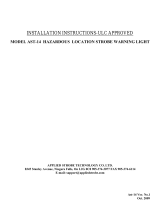
FIGURE 1. CANDELA AND SPEAKER SELECTOR LOCATIONS
Junction Box
(removed)
Speaker
Selector
Strobe Candela
Selector
A0589-00
INSTALLATION AND MAINTENANCE INSTRUCTIONS
L-Series Selectable Output
Drop-in Ceiling
Speaker Strobe, Speaker, and Strobe
For use with the following models. UL: SPSCWL-TILE, SPCWL-TILE, SCWL-TILE. ULC: SPSCWLA-TILE, SPCWLA-TILE, SCWLA-TILE.
PRODUCT SPECIFICATIONS
Standard Operating Temperature: 32°F to 120°F (0°C to 49°C)
Humidity Range: 10 to 93% Non-condensing
Nominal Voltage (speakers): 25 Volts or 70.7 Volts
Maximum Supervisory Voltage: 50 VDC
Speaker Frequency Range: 400 – 4000 Hz
Power Settings: ¼, ½, 1, 2 Watts
Input terminal wire gauge: 12 to 18 AWG
Strobe Flash Rate: 1 flash per second
Nominal Voltage (strobes): Regulated 12VDC, regulated 24VDC or FWR
Operating Voltage Range (includes fire alarm panels with built in sync): 8 to 17.5V (12V nominal) or 16 to 33V (24V nominal)
Operating Voltage with MDL3/A Sync Module: 8.5 to 17.5V (12V nominal) or 16.5 to 33V (24V nominal)
DIMENSIONS FOR PRODUCTS AND ACCESSORIES
Length Width Depth Weight
Speaker (SPCWL-TILE, SPCWLA-TILE)
23.69" (602 mm) 23.69" (602 mm) 3.29" (84 mm) 14.4 lb (6.53 kg)
Strobe (SCWL-TILE, SCWLA-TILE)
23.69" (602 mm) 23.69" (602 mm) 3.29" (84 mm) 14.2 lb (6.44 kg)
Speaker Strobe (SPSCWL-TILE, SPSCWLA-TILE)
23.69" (602 mm) 23.69" (602 mm) 3.29" (84 mm) 14.9 lb (6.76 kg)
Mounting Suspended Ceiling: Seismic tie-off points should be used for hanging the product from building structure. If ceiling is a 2'x4' grid, installer shall
subdivide the opening with a compatible T grid to create a 2'x2' cell for mounting the product.
NOTICE: This manual shall be left with the owner/user of this equipment.
3825 Ohio Avenue, St. Charles, Illinois 60174
800/736-7672, FAX: 630/377-6495
www.systemsensor.com
I56-6653-000

2 I56-6653-000
11/06/2020
FIGURE 2A. MOUNTED APPLIANCE (VIEWED FROM ABOVE)
A0590-01
FIGURE 2B. MOUNTED APPLIANCE WITH OPTIONAL CUSTOMER-
SUPPLIED EQUIPMENT (VIEWED FROM ABOVE)
A0595-00
FIGURE 2C. MOUNTED APPLIANCE (VIEWED FROM BELOW)
A0594-00
FIGURE 3. WIRING DIAGRAM (SPEAKER STROBE SHOWN)
(-) Violet
(+) Yellow
(+) Yellow
(-) Black
(+) Red
A0592-00
WIRING & SETTINGS
Wiring methods shall be in accordance with regional codes.
• United States: The National Electrical Code, NFPA 70, and the National
Fire Alarm and Signaling Code, NFPA 72.
• Canada: CSA C22.1, Canadian Electrical Code, Part I, Safety Standard for
Electrical Installations, Section 32.
Wiring must not be of such length or wire size which would cause the noti-
fication appliance to operate outside of its published specifications. Improper
connections can prevent the system from alerting occupants in the event of
an emergency.
1. To uncover the product wires and access hole, remove the junction box
with a Philips head screwdriver. (See Figure 1.)
2. Route the field wiring through the conduit connector.
3. Optional for rigid conduit applications or applications which require a
red junction box: Attach customer-supplied extension ring for alternate
cover. (See Figure 2B.)
4. Prepare the wire connections by stripping about
3
/
8
" of insulation from
the end of the field wiring. Terminate the wires using UL/ULC approved
wire nuts.
5. Connect wires for speakers and/or strobes. (See Figure 3.)
a. Speaker:
—Connect speaker INPUT from the Amplifier, Positive and Negative.
— Connect speaker OUTPUT to the next appliance or EOL resister.
b. Strobe:
— Connect the strobe INPUT from the FACP or NAC, Positive and
Negative.
— Connect the strobe OUTPUT to the next appliance or EOL resister.
NOTE: SUPERVISED STROBE INPUT POWER. System Sensor notifica-
tion appliances supervise the strobe power on the positive terminal. In-
put and output terminals are completely independent and must not be
shorted together.
6. Configure input power and/or candela settings.
a. Speaker: (See Figure 4.)
—Turn the VOLTS dial to select input voltage (25V or 70 V).
— Turn the WATTS dial to select input wattage (¼, ½, 1 or 2 W).
b. Strobe: (See Figure 5.)
— Loosen the cover plate on the back of the product with a Philips
head screwdriver and move it aside to access the candela switch.
— Use a small flat-head screwdriver to move the slider and select
candela (15, 30, 75, 95, 115, 150, 177).
— Reposition the cover plate and fasten securely.
7. Insert all wire connectors under junction box and replace cover.
8. Check that all cover plates and conduit connectors are secure.
MOUNTING AND REMOVAL INSTRUCTIONS
1. Insert appliance into the 2x2 opening on an angle and lay it onto the
grid.
2. Add additional support wires to the seismic tie off holes on the perimeter
of the appliance.
3. To remove: Disconnect seismic tie off wires, lift the appliance off the T-
grid, and lower through opening on an angle.
CAUTION
Factory finish should not be altered: Do not paint!

3 I56-6653-000
11/06/2020
SPEAKERS
System Sensor offers a wide range of power settings for your life safety needs,
including ¼, ½, 1, and 2W.
Sound levels data per UL 1480 can be found in Table 1.
FIGURE 4. SPEAKER WATTAGE AND VOLTAGE SETTINGS
A0593-00
TABLE 1. SOUND LEVELS FOR EACH TRANSFORMER POWER SETTING
Setting UL Reverberant (dBA @10 ft) UL Anechoic (dBA @10 ft)
¼ W 77 79
½ W 80 82
1 W 83 85
2 W 86 88
TABLE 2. DIRECTIONAL SOUND CHARACTERISTICS
Angle (degrees) Decibels
+/- 50-degrees -3dB
+/- 95-degrees -6dB
CAUTION
Signal levels exceeding 130% rated signal voltage can damage the speaker.
Consequently, an incorrect tap connection may cause speaker damage. This
means that if a 25V tap is selected when a 70.7V amplifier is being used,
speaker damage may result. Therefore, be sure to select the proper taps for the
amplifier voltage/input power level combination being used.
STROBES
FIGURE 5. CANDELA SELECTOR
A0486-01
FIGURE 6. LIGHT OUTPUT - VERTICAL DISPERSION, CEILING TO WALLS
TO FLOOR
Minimum light output requirements per UL1971
A0468-00
Candela Setting
Degrees*
Percent
of Rating 15 30 75 95 115 150 177
0 100 15 30 75 95 115 150 177
5-25 90 13.5 27.0 67.5 85.5 103.5 135.0 159.3
30-45 75 11.3 22.5 56.3 71.3 86.3 112.5 132.8
50 55 8.3 16.5 41.3 52.3 63.3 82.5 97.4
60 45 6.8 13.5 33.8 42.8 51.8 67.5 79.7
65 35 5.3 10.5 26.3 33.3 40.3 52.5 62.0
70 35 5.3 10.5 26.3 33.3 40.3 52.5 62.0
75 30 4.5 9.0 22.5 28.5 34.5 45.0 53.1
80 30 4.5 9.0 22.5 28.5 34.5 45.0 53.1
85 25 3.8 7.5 18.8 23.8 28.8 37.5 44.3
90 25 3.8 7.5 18.8 23.8 28.8 37.5 44.3
TABLE 3. CEILING-MOUNT STROBE CURRENT DRAW (mA)
Candela
Current Draw
(mA)
Current Draw (mA)
18-17.5 Volts 16–33 Volts
DC
DC FWR
15
87
41 60
30
153
63 86
75
-
111 142
95
-
134 164
11 5
-
158 191
150
-
189 228
177
-
226 264
*NOTE: Products set at 15 and 30 candela automatically work on either 12V
or 24V power supplies. The products are not listed for 12V DC operation when
set to any other candela settings.

4 I56-6653-000
©2020 System Sensor. 11/06/2020
System Sensor
®
is a registered trademark of Honeywell International, Inc.
Always make sure that the individual speakers are tested after installation per NFPA/
ULC regulations. The speakers may not be heard. The loudness of the speaker meets (or
exceeds) current Underwriters Laboratories’ standards. However, the speaker may not
alert a sound sleeper or one who has recently used drugs or has been drinking alcoholic
beverages. The speaker may not be heard if it is placed on a different floor from the
person in hazard or if placed too far away to be heard over the ambient noise such as traf-
fic, air conditioners, machinery or music appliances that may prevent alert persons from
hearing the alarm. The speaker may not be heard by persons who are hearing impaired.
WARNING
THE LIMITATIONS OF SPEAKERS
FCC STATEMENT
System Sensor Strobes and Horn/Strobes have been tested and found to comply with the
limits for a Class B digital device, pursuant to part 15 of the FCC Rules. These limits are
designed to provide reasonable protection against harmful interference when the equip-
ment is operated in a commercial environment. This equipment generates, uses, and
can radiate radio frequency energy and, if not installed and used in accordance with the
instruction manual, may cause harmful interference to radio communications. Operation
of this equipment in a residential area is likely to cause harmful interference in which
case the user will be required to correct the interference at his own expense.
For the latest Warranty information, please go to:
http://www.systemsensor.com/en-us/Documents/E56-4000.pdf
For Limitations of Fire Alarm Systems, please go to:
http://www.systemsensor.com/en-us/Documents/I56-1558.pdf
Speakers only: For the latest Important Assembly Information, please go to:
http://www.systemsensor.com/en-us/Documents/I56-6556.pdf
Warranty
Limitations of
Fire Alarm Systems
Speakers Only:
Assembly Information
SUPPLEMENTAL INFORMATION
DEVICE AND SYSTEM SECURITY
Before installing this product ensure that the tamper seal on the packaging is present and unbroken and the product has not been tampered with since leaving the factory. Do not
install this product if there are any indications of tampering. If there are any signs of tampering the product should be returned to the point of purchase.
It is the responsibility of the system owner to ensure that all system components, i.e. devices, panels, wiring etc., are adequately protected to avoid tampering of the system that could
result in information disclosure, spoofing, and integrity violation.
/