Page is loading ...

1
American Trail Products (Part # 37150001)
Renegade Roof Rack System
Installation Instructions
Always read instructions completely before beginning installation of any
American Trail Products.
PARTS LIST AND TOOLS REQUIRED:
PART DESCRIPTION QTY PER KIT
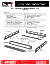
Front Panel Front or Roof Rack 1
Rear Panel Rear of Roof Rack 1
Side Panels Left & Right Sides of Roof Rack 2
Cross Bars Cross Bars Marked On End 5
Center Support Ties Cross Bars Together 1
Front Panel Support Brace Bolts to Rear Of Front Panel 1
American Trail Products, LLC
817 East Lambert Road
La Habra, CA 90631
Phone (877) 360-5337
Email: [email protected]
TOOLS REQUIRED FOR THIS INSTALLATION (Special Edition Models May Differ)
Allen Wrenches - 5mm, 4mm
Wrench or Socket - 10mm
HARDWARE DESCRIPTION QTY PER KIT
Nut, Stover M6 36
Washer M6 46
Bolt, Socket Head M6 x 1.0 x 10 8
Bolt, Button Head M6 x 1.0 x 16 28
Bolt, Button Head M6 x 1.0 x 12 5
Bolt, Button Head M6 x 1.0 x 30 5

2
Step 1. Remove Products from Packaging.
(A) Place all parts on a clean protected surface.
(B) Verify kit contents (see page 1) and inspect for damage.
Step 2. Molding Removal.
Begin by removing the molding from the roof (both sides). You will
need to start from the front edge using a small flat blade screw-
driver to get under the molding and lift up to remove.
Next, locate the front panel and brace (see fig 2) line up the holes and assemble using supplied M6 x
12MM button head hardware. (Note: the bolt head should be on the front (See Fig 4).
Now, place the side rails into position with logo at rear of vehicle (see fig 5) and install the M6 x
10MM socket head hardware to attach the rails to the roof (see fig 6) (leave rails loose at this time) Now
repeat on the other side. Next, slide both rails as far back as possible and tighten the hardware.
(some hardware is hard to get to once the front panel is installed)
Step 3. Front Panel Brace.
Step 4. Roof Side Rail Installation.
Brace
Fig 4
Fig 3
Fig 2
Fig 5 Fig 6 Fig 7
Fig 1

3
You’re finished! There is one last thing we would like you to due. Take pic-
tures or video of your Jeep and post it on Our social media showing your
American Trail Products installed. We may send you something as a thank
you for your effort. Thank you for choosing American Trail Products! Any
questions or comments call 877-360-JEEP.
Step 5. Front And Rear Panel Installation.
Next, place the front panel between the two side panels (fig 8) line up the top end of the front panel with the top
edge of the rack and bolt together using the supplied M6 x 16 button head bolts, washers and nuts (fig 9).
Now, place the rear panel between the two side panels (fig 10) and bolt together using the supplied M6 x 16
button head bolts, washers and nuts (fig 11).
Step 6. Cross Bar And Center Support Installation.
Fig 8 Fig 9 Fig 10 Fig 11
Fig 12 Fig 13
Next, identify the cross bars by locating the number stamped on the end of the plates, now starting at the front
of the vehicle place bar marked 1 in the forward position, then 2, 3, 4 with 5 being the last bar at the rear of the
vehicle. line up the five cross bars between the two side panels (fig 12) line up the holes on the cross bar with
the holes on the side panel and bolt together using the supplied M6 x 16 button head bolts (fig 13) (leave rails
loose at this time) Now, install the lower hardware (fig 14) using the supplied M6 x 16 button head bolts, wash-
ers and nuts (leave rails loose at this time). Now, install the center support (fig 15)
**Note: Cross bars can be flipped over during install to create a shallow basket if desired**
Fig 14 Fig 15
Step 6. Center Support And Final Hardware Installation.
Fig 16 Fig 17
Next, line up the center support with the holes in the cross bars and bolt together using the supplied M6 x 30
button head bolts, washers and nuts (see fig 16/17) Now, you can complete your install by tightening all roof
rack hardware (see fig 18).
Fig 18
/

