Page is loading ...

1 of 5
©2011 Tyco Electronics Corporation, a TE Connectivity Ltd. Company
All Rights Reserved
TE logo is a trademark.
*Trademark. Other products, logos, and company names might be trademarks of their respective owners.
Instruction Sheet
TOOLING ASSISTANCE CENTER
1-800-722-1111
PRODUCT INFORMATION
1-800-522-6752
This controlled document is subject to change.
For latest revision and Regional Customer Service,
visit our website at www.te.com
LOC B
Self-Locking
Metrimate Connectors 408-7846
11 APR 11 Rev B
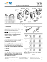
Figure 1
1. INTRODUCTION
This instruction sheet covers the assembly of the Self-
Locking Metrimate Connectors shown in Figure 1.
These connectors have metric and U.S. customary
dimensions which meet international standards (UL,
VDE, IEC, and CSA International). For specific
information concerning the connectors, contact Tyco
Electronics at the number at the bottom of this page.
Dimensions in this instruction sheet are in
millimeters [with inches in brackets]. Figures and
illustrations are for reference only and are not
drawn to scale.
Reasons for revision to this document are given in
Section 10, REVISION SUMMARY.
2. DESCRIPTION
The connectors consist of a housing plus the contacts
and wires. The connectors are available with 4-, 6-, 9-,
12-, 18-, 24-, and 36-positions. Each consist of a one-
piece housing (plug or receptacle) and contacts (pins
or sockets). The connectors can be used for free-
hanging or panel-mounted applications.
Each housing features two locks with serrated
releases, panel latches, polarization, cavity numbers,
and a raised collar around the No. 1 cavity. Refer to
Figure 3.
The panel latches are designed to retain a connector
in a panel. The panel latches deflect to permit insertion
and extraction through a FRONT or BACK of a panel.
The locking tabs will secure two mated connections
and retain them until two serrated releases of either
connector are depressed. This feature avoids
inadvertent disengagement, and permits the
connectors to be used for both free-hanging and
panel-mounted applications.
Socket Contact Panel Latches
Serrated
Release
Socket Housing (Plug)
Polarization
Featurees
Keying Plug 207654 Pin Housing (Receptacl)e
Serrated
Release
Pin Contact
Locking Tab
Keying Plug
200821
NUMBER OF
POSITIONS
HOUSING PART NUMBER ACCESSORIES
PLUG RECEPTACLE STRAIN-RELIEF ASSEMBLY KEYING PLUG
4 207015 207016 - - -
200821
or
207654
6 207152 207153 207600-1
9 207439 207440 207601-1
12 207017 207018 207602-1
18 207442 207443 207603-1
24 207304 207305 207088-1
36 207019 207020 207604-1
NOTE
i

408-7846
2 of 5
Rev B
Cavity numbers and the raised collar on the back of
each connector provide a visual means of identifying
each circuit.
Strain-relief assemblies and keying plugs are
accessories that can be used with these connectors.
The strain-relief assembly provides protection for
exposed and/or heavy cable bundles. The keying plug
provides additional polarization of connectors.
Each contact cavity will accept any of the various contacts in the
Multimate Program (Subminiature COAXICON* Contacts, Types II,
III(+), VI, and fiber optic). All of the contacts are size 16 with a pin
diameter of 1.6 [.062].
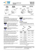
3. CONTACT SELECTION (Figure 2)
There are three forms of contacts: (1) loose-piece (all
styles), (2) tape-mounted strip (Type II only), and (3)
continuous metal strip (all styles except Type II and
fiber optic). The loose-piece contacts are for low-
volume applications, while the Type III (+) and Type VI
strip contacts are for high-volume applications.
Figure 2
Size 16 Pin
Wire Marking
Type VI
Contacts
Type III(+
Contacts)
Size 16 Pin
Socket
Type II Contacts
Barrel
Color
Code
Size 16
Pins
Long
Long-Long
(Grounding Pin)
Socket
Ferrule
Size 16 Multimate Pin
Ferrule
Subminiature COAXICON Contacts
Fiber Optic Contacts
Short Contact
(For Plug Connector)
Alignment Bushing
Long Contact
(For Receptacle
Connector)
CONDUCTOR MULTIMATE CONTACTS
TYPE SIZE TYPE DESCRIPTION
Coaxial Cable RG-161, 174•, 178, 179,
187, 188, 196•, and 316
Subminiature
Coaxicon
3--Piece (Screw Machine Inner Contact
Body with Precision Formed Outer Shell
and Ferrule)
Shielded (1.90 [.075] OD Max) 26 AWG
Twisted Pair (Solid and Stranded) 26 AWG
Twisted Pair (Solid) 28 AWG
Twisted Pair (Stranded) 28 AWG
Twisted Pair ((Solid) 30 AWG
Single Wire (Solid and Stranded)
32-14 AWG Type II Contact 2-Pieece (Screw Machine/Precision
Formed Spring)
26-14 AWG Type III (+) Contact 2-Piece (Precision Formedd Contact Body
and Spring)
28-14 AWG Type VI Contact 1-Piece (Precision Formed)
Fiber Optic (Solid and Stranded) 0.41, o.61, 1.12
[.016, .024, .046] Dia Fiber Optic Contact
4-Piece, Short Contact (Precision Formed
and Molded)
5-Piece, Long Contact (Precision formed
and Molded)
• Both single and double braid cable.

408-7846
3 of 5
Rev B
There are five styles of contacts as shown in Figure 2.
Make your selection as follows:
1. Determine the type and size of conductor
specified for your application.
2. Determine the contact style that you are going to
use. See Figure 2.
3. Refer to the instruction sheet packaged with the
contacts for contact and tool selection. If Type III(+)
or Type VI strip contacts are going to be used,
consult your local Tyco Electronics Representative
for the machine that will best suit your needs.
4. CONTACT INSERTION AND EXTRACTION
4.1. Insertion (Figure 3)
Normally an insertion tool is not needed to insert these
contacts. However, if the wire is too small and fragile,
or if the cable bundle is too large, Insertion Tool 91002
can be used to insert the contacts. When inserting
contacts, grip the wire directly behind the contact and
push the contact straight into the back of the
connector until it bottoms. Pull back lightly on the wire
to make sure the contact is locked in position.
4.2. Extraction (Figure 3)
Extraction Tool 305183 is designed to release contacts
through the front of the connector, and extract them
from the back. Read Instruction Sheet 408-1216
packaged with the tool for specific instructions.
Figure 3
5. KEYING PLUGS
Keying plugs 200821 and 207654 are designed for
use in plug connectors which mate with receptacle
connectors. However, keying plug 207654 can also be
used for plug connectors mating with pin headers.
1. Determine the applicable cavity to be keyed and
align the tapered end of the plug with the FRONT of
the connector.
2. Insert the keying plug straight into the cavity until
it bottoms. Approximately 3.18 [.125] of the keying
plug 200821 will protrude from the connector.
Keying plug 207654 will be flush with the mating
surface.
If removal of the keying plugs is necessary, remove
the 200821 plug by gripping it with pliers and pulling
the plug straight out the FRONT of the connector. To
remove keying plug 207654, insert Extraction Tool
305183 ( Refer to Instruction Sheet 408-1216) into the
BACK of the applicable cavity, depress the plunger,
and remove the keying plug from the FRONT of the
connector.
6. INSTALLING STRAIN-RELIEF ASSEMBLIES
Strain-relief assemblies consist of two symmetrical
halves and various sizes of strain-relief cable gates.
They can be attached to the connector for panel
mounting without interfering with the panel. Select and
install the strain-relief assembly as follows:
1. Determine the number of positions in the
housing, then refer to the table in Figure 1 and
select the applicable strain-relief assembly.
2. Gather the wires together and determine the
approximate opening required in the strain-relief.
(The wire bundle can be flat or circular as it exits the
strain-relief).
3. Select one or more cable gates packaged with
the strain-relief assembly and place in the strain-
relief track. Those with strain-relief ribs on both
sides can be inserted either side first. See Figure 4.
Several strain-relief cable gates have been
included to accommodate any number of wires
(one or more can be used). Notice that each gate is
numbered on the surface containing the strain-
relief ribs (some on both sides).
4. Align the slot tabs with the slots between the
panel locks and housing, then insert the tabs into
the slots. See Figure 4.
5. Bundle the wires together and place them on the
strain-relief gate. To avoid strain on the wire
between the connector and cable gate, push the
wire bundle toward the connector slightly.
Contact Insertion
Contact Extraction
Raised Collar
(No. 1 Cavity)
Back of
Connector
Pin Contact
(Ref)
Extraction
Plunger
Extraction Tool
305183
Front of Connector
Releasing
Tip
NOTE
i

408-7846
4 of 5
Rev B
Figure 4
6. Align the second strain-relief half with the
connector. Note that the slot tabs must be aligned
with the slots between the panel latches and
housing, and the strain-relief locking latches must
be aligned with the locking tabs.
7. Press the two halves together, making sure the
locking latches engages the locking tabs.
7. PANEL MOUNTING
The connector can be installed or removed from either
the FRONT or BACK of the panel. When only one
connector is to be panel mounted, we recommend that
you mount the plug connector. Make the panel cutout
and install the connector as follows:
1. Determine the number of positions in the
connector and make a cutout in the panel using the
dimensions provided in Figure 5.
2. Position the panel latch beams against the panel
and push the connector straight into the panel until
snapped in position.
To remove the connector from the panel, depress the
panel latch beams and push the connector through the
panel.
Figure 5
Panel Latches
Cable Gates
Slot Locking Latch Strain-Relief Ribs
Strain-Relief Track
Slot
Tab
Cable Gate (Typ)
Number
Marked
Here
Locking
Tab
NO. OF
POSN
DIMENSION S±0.15 [.006] PANEL
THICKNESS
AB
4 18.10 [.712] 20.30 [.799]
0.8-2.3
[.030-.090]
Max
6 18.10 [.712] 25.10 [.988]
9 24.00 [.945] 25.10 [.988]
12 24.00 [.945] 30.00 [1.81]
18 24.00 [.945] 40.50 [1.594]
24 28.30 [1.114] 40.50 [1.594]
36 28.30 [1.114] 55.50 [2.185]
Installed
Plug Patch Panel Beams

408-7846
5 of 5
Rev B
8. ENGAGING CONNECTORS
1. Check that the plug and receptacle have identical
positions. If keying plugs have been installed in the
plug connector, corresponding cavities must be
empty in the receptacle connector.
2. Orient connectors so polarizing features are
aligned.
3. Make sure the mating faces are parallel to each
other, then push the connector together until the
locks engage.
9. DISENGAGING CONNECTORS
When possible, we suggest that you remove the
longer connector (receptacle) from the shorter
connector (plug).
1. Simultaneously depress both serrated releases
of one connector. See Figure 6.
2. Pull the connectors straight away from one
another. They should separate easily.
Figure 6
Damaged product should not be used. If damaged
product is evident, it should be replaced.
10. REVISION SUMMARY
Since the previous release of this instruction sheet,
the company logo has been updated.
Plug Receptacle
Serrated Releases
CAUTION
!
/


