FIBER SYSTEM SOLUTIONS
P R O D U C T G U I D E


FIBER SYSTEM SOLUTIONS
INTRODUCTION page (2-3)
SYSTEM CONFIGURATION & FLOW page (4-5)
HYBRID FIBER CABLE ASSEMBLIES page (6-9)
DISTRIBUTION RACKS page (10-11)
BREAKOUT BOXES page (12-13)
DISTRIBUTION RACK ACCESSORIES & PARTS page (14)
CLEANING TOOLS & INSTRUCTIONS page (15)
PANELS page (16-19)
LEMO CONNECTORS page (20)
CANARE CONNECTORS page (21)
DUSTCAPS, BOOTS & INSTALLATION TOOLS page (22)
PANEL MOUNT FIBER CONNECTORS page (23)
TAC-4 & TAC-12 CABLE ASSEMBLIES page (24)
OPTICALCON® FIBER OPTIC CABLE ASSEMBLIES page (25)
ST/SC/LC CABLE ASSEMBLIES page (26-29)
9.2MM HYBRID FIBER OPTIC CABLE page (30-31)
12MM HYRID FIBER OPTIC CABLE page (32)
16MM HYBRID FIBER OPTIC CABLE page (33)
HD CAMERA ELECTRICAL CABLE page (34)
THREE-CHANNEL FIBER CABLE page (35)
SINGLE-MODE OPTICAL FIBER CABLE page (36)
MULTI-MODE OPTICAL FIBER CABLE page (36)
TACTICAL OPTICAL FIBER CABLE page (37-38)
INDEX page (39)
FIBER SYSTEM SOLUTIONS
TABLE OF CONTENTS


T
he leading innovator of interconnect technology for broadcast and pro A/V appli-
cations, Gepco delivers a full line of optical fiber solutions for high definition audio
and video applications. Engineered and manufactured to industry leading stan-
dards, Gepco fiber systems bring the optical clarity and reliability required for high-
bandwidth data transmission in television, video production,
staging, outdoor broadcast and professional audio appli-
cations. With a complete range of cable assemblies, pan-
els, components and accessories, Gepco’s optical fiber
systems product line provides a turn-key optical solution.
OPTICAL FIBER
SYSTEM SOLUTIONS
CABLE ASSEMBLIES | DISTRIBUTION SYSTEMS | REPAIRS | CABLE & CONNECTORS
Broadcast and Pro A/V
Hybrid SMPTE HD Cameras
Tactical Applications
Distribution Systems
Components
Test Equipment and Accessories

www.gepco.com | 800.966.0069
FIBER SYSTEM SOLUTIONS
4
SMPTE 304M/311M Hybrid Fiber
Direct Cable Termination Configuration
Lowest System Attenuation
Utilized SMPTE 304M Panel Mount Connectors
Field Terminated or Factory Terminated (If Installed with Body
Removal and Installation Adapter)
Blank Panels Available in Straight or Angled Configurations
Hybrid Cable Assembly
See Page 6
See Page 6
See Page 7See Page 16
See Page 16 See Page 7 See Page 16
++
CAMERA
CCU
The Direct Cable termination method is achieved with panel mount
SMPTE 304M hybrid fiber connectors directly terminated onto the hybrid
cable that permanently interconnects between panels, junction boxes,
and control room racks. Panel mount SMPTE 304M connectors offer
the lowest overall insertion-loss at each breakout point. Panel Mount
connector must be field terminated or factory terminated and installed
on-site with the DCS.3K.175.72LN installation tool.
from Camera to Panel
Panel Loaded with Bulkheads
at Studio or Camera Location
Socket and Plug Assembly
Interconnects Between Blank Panels
Panel Loaded with Bulkheads
at Machine Room Location
Hybrid Cable Assembly
for Patching Between Panels
Panel Loaded with Bulkheads
at Machine Room Location
Plug Bulkhead Assembly
Interconnect from Panel to CCU

www.gepco.com | 800.966.0069
FIBER SYSTEM SOLUTIONS
5
SMPTE 304M/311M Hybrid Fiber
Distribution Rack Configuration
Easy to Field-install and Terminate
Modular Channels can be Reconfigured On-site
Replaceable Contact Jumpers for Field Serviceability
Does not Require Specialized Labor or Tooling
Uses Cost Effective, General Purpose Fiber
and Electrical Cables
CAMERA
See Page 6 See Page 10 See Pages 34 & 36
See Page 10 See Page 6 See Page 10
CCU
See Page 8
Gepco HDR and HDRA distribution racks offer an exceptionally flexible
and modular solution to the field deployment and installation of perma-
nent installation SMPTE hybrid camera cables. With the Distribution
Rack method, SMPTE 304M connectors are broken out to separate elec-
trical and optical elements on the back of the distribution rack. These
separate elements can then be readily terminated to fiber and electrical
cabling without the need for the specialized labor or tooling required
for the termination of SMPTE hybrid fiber.
Hybrid Component Breakout
Interconnects Back of HDR to CCU
Distribution Rack
at Machine Room Location
Hybrid Cable Assembly
for Patching Betwween Distribution Racks
Distribution Rack
at Machine Room Location
Hybrid Cable Assembly
from Camera to Panel
Distribution Rack
at Studio or Camera Location
Single-mode Fiber & Electrical Cable
Interconnects Between Distribution Racks

www.gepco.com | 800.966.0069
FIBER SYSTEM SOLUTIONS
6
Cable Type
HDC120P
Connector Type
SMPTE 304M Hybrid Connectors - 1 Plug,
1 Socket with Metal Dust Caps
Standard Lengths
50’, 100’, 164’, 250’, 328’, 500’, 656’
Options
Lemo or Canare Connectors
SMPTE 304M/311M Hybrid Fiber Cable Assemblies
Portable: Heavy-duty 12mm Type
Cable Type
HDC920
Connector Type
SMPTE 304M Hybrid Connectors - 1 Plug,
1 Socket with Metal Dust Caps
Standard Lengths
50’, 100’, 164’, 250’, 328’, 500’, 656’
Options
Lemo or Canare Connectors
Overbody Rubber Boot
Portable: Thin Profile 9.2mm Type
PART NUMBER: GHF12B-0-(length)
PART NUMBER: GHF92A-0-(length)
Gepco GHF hybrid fiber and copper camera cables, terminated with
SMPTE 304M connectors for high definition video camera to CCU in-
terconnects.
Gepco SMPTE hybrid fiber cables utilize two single-mode fibers for high
bit-rate signal transmission and copper elements for auxiliary and sig-
nal electrical connections. Each fiber is coated with a high tensile
strength coating for exceptional durability and strength. The copper
elements feature a heat resistant PE insulation material for dependable
performance in high temperature environments.
Fiber contacts are machine polished to meet or exceed all SMPTE stan-
dards. With typical UPC performance of -55dB RL, Gepco hybrid fiber
cables achieve exceptional optical clarity to deliver reliable perform-
ance and low transmission loss.
Machine Polished
-55dB Return Loss (Typical)
Portable, Extra-rugged, and Permanent Install Versions
Lemo or Canare Connectors
Extra-rugged Designs
Heat Resistant
Meets or Exceeds SMPTE 304M/311M Standards
(One end shown with optional overbody
boot. Please specify when ordering.)
F E AT U R ES & B E N E FI T S
-OB Add for Overbody Boot Option

www.gepco.com | 800.966.0069
FIBER SYSTEM SOLUTIONS
7
SMPTE 304M/311M Hybrid Fiber Cable Assemblies
Cable Type
HDC920R
Connector Type
SMPTE 304M Hybrid Connectors - 1 Plug,
1
Socket with Metal Dust Caps
Standard Lengths
5
0’, 100’, 164’, 250’, 328’, 500’, 656’
Options
Lemo or Canare Connectors
Standard In-line: Permanent Installation
Cable Type
HDC920R
Connector Type
SMPTE 304M Hybrid Connectors - 1 Plug Bulk-
head, 1 Socket with Metal Dust Caps
Standard Lengths
50’, 100’, 164’, 250’, 328’, 500’, 656’
Options
Lemo or Canare Connectors
Plug Bulkhead: Permanent Installation
PART NUMBER: GHF92B-0-(length)
PART NUMBER: GHF92B-0-(length)-PB
Cable Type
HDC920R
Connector Type
SMPTE 304M Hybrid Connectors - 1 Plug,
1 Socket Bulkhead with Metal Dust Caps
Standard Lengths
50’, 100’, 164’, 250’, 328’, 500’, 656’
Options
Lemo or Canare Connectors
Socket Bulkhead: Permanent Installation
PART NUMBER: GHF92B-0-(length)-SB
Cable Type
HDC920R
Connector Type
SMPTE 304M Hybrid Connectors - 1 Plug Bulk-
head, 1 Socket Bulkhead with Metal Dust Caps
Standard Lengths
50’, 100’, 164’, 250’, 328’, 500’, 656’
Options
Lemo or Canare Connectors
Plug & Socket Bulkhead: Permanent Installation
PART NUMBER: GHF92B-0-(length)-SPB

www.gepco.com | 800.966.0069
FIBER SYSTEM SOLUTIONS
8
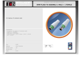
Gepco hybrid fiber breakout cables offer an in-line solution
for breaking out SMPTE 304M Hybrid connectors to sep-
arate optical and electrical connectors. This solution
allows for the interfacing of SMPTE hybrid camera
devices, such as CCUs, directly to the back of a
Gepco HDR/HDRA distribution rack.
As with all Gepco GHF cables, the breakout
series is machine polished to meet or ex-
ceed all SMPTE 304M/311M standards.
Terminated with HDC920R riser rated
9.2mm cable, breakout cables can be
used in most permanent installation en-
vironments.
ST/SC/LC Optical Breakout
AMP Electrical Breakout
Machine Polished to -55dB RL (Typical)
CMR Rated 311M Hybrid Cable for Permanent
Installation
Available in Short or Long Cable Lengths
For Interfacing SMPTE Hybrid Devices with the Back Panel of
Distribution Panels or Other Component Level Devices
F E AT U R ES & B E N E FI T S
Electrical Connector Options
ABC
E F
G H
Fiber Connector Options
ST SC LC
GHF92B
Length
(First End)
Connector Format
(Second End)
Fiber Breakout
-- /
P = Plug
PB = Bulkhead Plug
S = Socket
SB = Bulkhead Socket
ST = ST UPC
SC = SC UPC
LC = LC UPC
DSC = Duplex SC UPC
DLC = Duplex LC UPC
Standard Gender
A = 5-pin AMP Metal CPC (for Mating with HDR & HDRA Racks)
B = 8-pin AMP CPC
C = 6-pin AMP MATE-N-LOCK Cap
D = Blunt
Reverse Gender
E = 5-pin Reverse Gender CPC - In-line or Panel Mount
F = 8-pin Reverse Gender CPC - In-line
G = 8-pin Reverse Gender CPC - Panel Mount
H = 6-pin Reverse Gender MATE-N-LOCK
In Feet
(Second End)
Electrical Breakout
Hybrid Fiber Breakout: In-line Cable
Standard Gender Reverse Gender

www.gepco.com | 800.966.0069
FIBER SYSTEM SOLUTIONS
9
Hybrid Fiber internal distribution cables do not use conven-
tional hybrid 311M cables and are intended for internal
equipment or panel wiring only. The SMPTE 304M
end uses OEM style, non-cable-mount hybrid con-
nectors and is terminated to insulated copper wire
and individual, simplex breakout fibers. The
component breakout end has ST, SC, or LC
optical connectors, while the copper ele-
ments feature AMP or blunt ends.
As with all Gepco GHF cables, the break-
out series is machine polished to meet or
exceed all SMPTE 304M/311M stan-
dards.
ST/SC/LC Optical Breakout
AMP Electrical Breakout
Machine Polished to -55dB RL (Typical)
Uses Short Length Fiber and Electrical Elements
For Panel Mounting in Blank Panels or as a Replacement
in Hybrid Devices
F E AT U R ES & B E N E FI T S
GHFBK
Length
(First End)
Connector Format
(Second End)
Fiber Breakout
-- /
PB = Bulkhead Plug
SB = Bulkhead Socket
ST = ST UPC
SC = SC UPC
LC = LC UPC
DSC = Duplex SC UPC
DLC = Duplex LC UPC
Standard Gender
A = 5-pin AMP Metal CPC (for mating with HDR & HDRA Racks)
B = 8-pin AMP CPC
C = 6-pin AMP MATE-N-LOCK Cap
D = Blunt
Reverse Gender
E = 5-pin Reverse Gender CPC - Inline or Panel Mount
F = 8-pin Reverse Gender CPC - Inline
G = 8-pin Reverse Gender CPC - Panel Mount
H = 6-pin Reverse Gender MATE-N-LOCK
In Feet
(Second End)
Electrical Breakout
Hybrid Fiber Breakout: Internal Distribution
Electrical Connector Options
ABC
E F
G H
Fiber Connector Options
ST SC LC
Standard Gender
Reverse Gender

www.gepco.com | 800.966.0069
FIBER SYSTEM SOLUTIONS
10
The HDR system of hy-
brid fiber distribution
racks distributes the
electrical and fiber
components of the
SMPTE hybrid connec-
tors over separate op-
tical and electrical
components allowing
for simplified in-wall in-
stallation. The discrete
optical and electrical el-
ements between boxes
can now be interconnected with conventional distribution-type fiber and
Gepco's HDP electrical cable, thereby eliminating the need for special-
ized on-site hybrid fiber termination.
In addition, the HDR system offers improved field serviceability. The
internal fiber jumpers can be easily replaced when damaged or worn,
eliminating the costly need to completely replace the SMPTE hybrid con-
nectors. The HDR chassis is constructed from rugged, powder-coated
steel, all optical components feature machine-polished ceramic ferrules
with ceramic sleeves, and the electrical connectors are rugged, metal-
shell CPC types.
Hybrid Fiber Distribution Racks
1
2
4
5
3
AMP 5-pin Electrical Pinout
Pin 1 = Gray signal conductor (low voltage)
Pin 2 = Red signal conductor (low voltage)
Pin 3 = White auxiliary conductor (high voltage)
Pin 4 = Black auxiliary conductor (high voltage)
Pin 5 = Ground
ST Fiber Code
Fiber A = Top blue fiber in hybrid connector
Fiber B = Lower yellow fiber in hybrid connector
AMP 5-pin: Front View
Rear Panel Breakout per Channel
Assemblies & Specifications
Part #
# of
Channels
Connectors Dimensions
Chassis
Material/Color
Optical
Specifications
Comments
Hybrid Fiber Distribution Rack
SMPTE 304M Connector to ST and Electrical Breakout
HDR-#x
or
HDRA-#x
1, 2, 3, 4,
5, or 6
Front:
SMPTE 304M Hybrid Fiber
Connectors with Metal Dust
Caps (1 per channel)
Rear:
ST Female Metal Barrels
(Ceramic Sleeve) Internally
Coupled to Metal Body ST
Connectors (2 per channel)
AMP Metal-shell 5-pin CPC
Receptacle (1 per channel)
Straight:
1.75” High
(1RU)
x 19” Wide
x 3” Deep
Angled:
3.5” High
(2 RU)
x 19” Wide
x 3 ¾” Deep
Angled Front Panel
Steel/Black
Single-mode Optical Fiber, 8.3µ Mode Field,
125µ Cladding Diameter
>45dB @ 1310nm Return Loss ST Contacts
(PC Machine-polished)
>45dB @ 1310nm Return Loss Hybrid
Contacts (Machine-polished)
<0.50 dB @ 1310nm Total Insertion Loss
per Fiber Element
SMPTE 304M Compliant
Lemo F2 fiber contacts in the
hybrid connectors break out
to two female ST connectors
per channel. Auxiliary con-
tacts, signal contacts and
ground break out to the five
contacts in the CPC connector.
One, two and three channel
versions can be expanded to
four.
Part # Code x = Gender of Hybrid Fiber Connectors (P = Plug, S = Socket)
# = Number of Channels
Breaks Out Lemo HD Camera Connectors to Discrete
Electrical & Fiber Connectors
Machine-polished Optical Contacts & Ceramic Sleeves
Easy to Field Install
Replaceable Fiber Jumpers
Expandable up to Six Channels
1RU Chassis or 2RU Angeled Chassis Versions
F E AT U R ES & B E N E FI T S

www.gepco.com | 800.966.0069
FIBER SYSTEM SOLUTIONS
11
Hybrid Fiber Distribution Racks
HDR-4S Front View and HDR-4(P or S) Rear View
Front
Rear
HDR-6P Front View and HDR-6(P or S) Rear View
Front
Rear
HDRA-4S Front View and HDRA-4(P or S) Rear View
Front
Rear
HDRA-6P Front View and HDRA-6(P or S) Rear View
Front
Rear

www.gepco.com | 800.966.0069
FIBER SYSTEM SOLUTIONS
12
The HBB series of portable SMPTE 304M boxes
breaks out the hybrid camera con-
nector to two ST female con-
nectors on a recessed,
protective metal top-plate with
optional electrical connectors.
The breakout of the hybrid con-
nector to discrete, industry-stan-
dard optical and electrical
components allows for an HD
camera to CCU interconnection
over existing fiber tie-lines in facilities
where hybrid fiber interconnects may
not be present.
All optical components feature machine-polished ceramic ferrules and
ceramic sleeves for superior optical alignment and low loss. The chas-
sis is constructed from heavy-gage anodized aluminum for use in re-
mote production environments. In addition to the standard
configuration, the HBB breakout box is also available with XLR or 5-pin
AMP connectors that are hard wired to the power and/or signal com-
ponents of the SMPTE hybrid connectors.
Breaks Out SMPTE 304M Connector to Interface with Exist-
ing SM Fiber Tie-lines
Machine-polished Optical Contacts & Ceramic Sleeves
Replaceable Fiber Jumpers
Rugged Aluminum Chassis
Optional XLR or 5-pin AMP Connectors
Includes Metal Dust Caps
Hybrid Fiber Breakout Boxes
Assemblies & Specifications
Part #
# of
Channels Connectors
Optional
Electrical Connector
Chassis
Dimensions
Chassis
Material
Optical
Specifications
Hybrid Fiber to ST Breakout Box
Three-channel, 9” Long Chassis
HBB903xy 3 (6) Female ST Barrels
with Dust Caps (Metal
Housing, Ceramic Sleeve)
Internally Coupled with
Metal Body ST Connectors
with Ceramic Ferrules
(3) Hybrid Fiber SMPTE
304M Connector (Plug
or Socket) with Metal
Dust Caps
(3) 5-pin Amp CPC
Connector
-or-
(3) Male or
Female XLR
(Power elements
from fiber are not
terminated.)
Also available without
electrical connectors.
4.5” High x
5.25” Wide x
9” Long
1/8” Extruded
Aluminum
(Black Anodized)
Single-mode Optical Fiber, 8.3µ Mode Field,
125µ Cladding Diameter
>45dB @ 1310nm Return Loss ST Contacts
(PC Machine-polished)
>45dB @ 1310nm Return Loss Lemo F2
Contacts (Machine-polished)
<0.50dB @ 1310nm Total Insertion Loss
per Fiber Element
SMPTE 304M Compliant
Hybrid Fiber to ST Breakout Box
Single-channel, Small Footprint Type
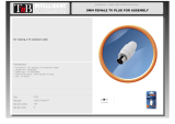
HBB901xy/4.5 1 (2) Female ST Barrels
with Dust Caps (Metal
Housing, Ceramic Sleeve)
Internally Coupled with
Metal Body ST Connectors
with Ceramic Ferrules
(1) Hybrid Fiber SMPTE
304M Connector (Plug
or Socket) with Metal
Dust Caps
(1) 5-pin Amp CPC
Connector
-or-
(1) Male or
Female XLR
(Power elements
from fiber are not
terminated.)
Also available without
electrical connectors.
4.5” High x
5.25” Wide x
4.5” Long
1/8” Extruded
Aluminum
(Black Anodized)
Single-mode Optical Fiber, 8.3µ Mode Field,
125µ Cladding Diameter
>45dB @ 1310nm Return Loss ST Contacts
(PC Machine-polished)
>45dB @ 1310nm Return Loss Lemo F2
Contacts (Machine-polished)
<0.50dB @ 1310nm Total Insertion Loss
per Fiber Element
SMPTE 304M Compliant
Part # Code x = Gender of Lemo Connectors (P = Plug, S = Socket)
y = Gender of Electrical Connectors (XF = Female XLRs, XM = Male XLRs, A = Amp 5-pin CPC)
F E AT U R ES & B E N E FI T S

www.gepco.com | 800.966.0069
FIBER SYSTEM SOLUTIONS
13
Hybrid Fiber Breakout Boxes
1
2
4
5
3
ST Fiber Code
Fiber A = Top blue fiber in hybrid connector
Fiber B = Lower yellow fiber in hybrid connector
AMP 5-pin Electrical Pinout (Optional)
Pin 1 = Gray signal conductor (low voltage)
Pin 2 = Red signal conductor (low voltage)
Pin 3 = White auxiliary conductor (high voltage)
Pin 4 = Black auxiliary conductor (high voltage)
Pin 5 = Ground
XLR Pinout (Optional)
Pin 1 = Ground
Pin 2 = Red signal conductor (low voltage)
Pin 3 = Gray signal conductor (low voltage)
Black & white power elements in hybrid fiber
connector are floated with no connector.
AMP 5-pin: Front View
Side Panel Electrical Connector Options
AMP 5-Pin XLR Male XLR Female
HBB903 Top View
HBB903 Side View
(SMPTE 304M Plug Side)
HBB903 Side View
(5-pin AMP CPC Side)
HBB901 Side View
(Female XLR Side)
HBB901 Side View
(SMPTE 304M Socket Side)
HBB901 Top View

www.gepco.com | 800.966.0069
FIBER SYSTEM SOLUTIONS
14
Hybrid Fiber Rack Accessories & Parts
REPLACEMENT PARTS AND TOOLS
P
art Number
D
escription
HDR-JMP-F2/ST Replacement F2 to ST Internal Jumper
AMP-66182-1 Replacement AMP Pins
AMP-305183 AMP Pin Extraction Tool
AMP-208719-1 Amp 5-pin Panel Mount Connector
CABLE MOUNT ELECTRICAL CONNECTORS
Part Number Description
AMP-208718-1 AMP 5-pin Cable Mount CPC Plug
AMP-208945-5 AMP CPC Metal Shell with Clamp
AMP-66183-1 Amp CPC Socket (for 26 - 20 AWG Wire)
AMP-66181-1 Amp CPC Socket (for 18 - 16 AWG Wire)

www.gepco.com | 800.966.0069
FIBER SYSTEM SOLUTIONS
15
Cleaning Tools & Instructions
ALIGNMENT REMOVAL TOOLS
P
art Number
D
escription
DCS.F2.035.PN
D
ual-ended Tool for Plug-end Alignment Sleeve Removal
of SMPTE 304M Connectors
D
CS.91.F23.LA
Single-ended Tool for Plug-end Alignment Sleeve Removal
o
f SMPTE 304M Connectors with Cotton Swab Resevoir
CLEANING SWABS AND TOOLS
P
art Number
D
escription
Q
uantity per Package
WST.KI.125.34
Premoistened Cotton Swabs - Pack of 2
(One Dry, One Wet) for SMPTE 304M, ST,
SC, or LC Contacts
2
GEP-HFCS
Bag of 100 Cotton Swabs (Not Premoistened)
for SMPTE 304M, ST, SC, or LC Contacts
100
SCK-SC-250
Cleaning Tool for Female Panel Mount ST, SC
or Other 2.5mm Fiber Contacts
1 (525+ Cleaning Uses)
SCK-SC-125
Cleaning Tool for Female Panel Mount LC or Other
1.25mm Fiber Contacts
1 (525+ Cleaning Uses)
MICROSCOPE KITS
Part Number Description
WST.CI.100.1A
Microscope Kit - Includes Scope, LCD Display, Positioner for F2 SMPTE 304M
Fiber Contacts, Positioner for 2.5mm Fiber Contacts, Battery and Charger,
DCS.F2.035.PN Extraction Tool, Carrying Case
WST.CI.201.1A
Includes all of the Components in the Standard WST.CI.100.1A Kit, Plus a Visual
Fault Finder with Tip, Launch Cable for Fault Finder, and 50 Premoistened Cotton
Swabs
CABLE TESTER
Part Number Description
FCT-FCKIT
Field Test Set for SMPTE 304M Hybrid Fiber Cables - Tests for Insertion and Return
Loss, and Electrical Continuity for Shorts/Opens - Does not Fault Locate Damage

www.gepco.com | 800.966.0069
FIBER SYSTEM SOLUTIONS
16
Gepco HBP panels offer a pre-engineered solution for the mounting of
SMPTE 304M hybrid fiber connectors in a 19” rack. Available in 1RU,
2RU, and angled 2RU versions, all panels feature Gepco’s unique Uni-
versal Punch Mount that allows for plug or socket connectors to be
mounted in any position. Each position also features a hole for mount-
ing the dust cap lanyard eyelets directly to the panel.
The HBP panels are used in the Direct Cable Termination method (see
page four for system configuration details). When using HBP panels
with pre-terminated cable assemblies, the connector body of the cable
assembly can be removed, allowing for the assembly to be passed
through the panel hole punch from the rear and reassembled from the
front.
Angled 2RU Panel
Hybrid Fiber Blank Panels
1RU, 2U, or Angled 2RU Versions
Universal Punch Mount Accommodates Plug or Socket
Connectors (Does Not Accommodate PEW Connectors)
Works with Lemo or Canare Brand Connectors
Additional Hole for Dust Cap Lanyard Mounting
Can Be Loaded with Pre-terminated Cable Assemblies
PART NUMBER: HBPA-*U
* Designates Number of Holes (1-6)
F E AT U R ES & B E N E FI T S
NNoottee::
Custom panels are also available. Please contact Gepco for details.
Straight 2RU Panel
PART NUMBER: HBP2-*U * Designates Number of Holes (1-6)
Straight 1RU Panel
PART NUMBER: HBP1-*U * Designates Number of Holes (1-6)
Ideal for Use With Bulkhead or Breakout Hybrid Fiber Cable Assemblies:
Bulkhead Hybrid
((SSeeee ppaaggee 77))
In-line Breakout
((SSeeee ppaaggee 88))
Internal Breakout
((SSeeee ppaaggee 99))

www.gepco.com | 800.966.0069
FIBER SYSTEM SOLUTIONS
17
Modular Isolation Panel System
Type Part Number Application Material Dimensions
Modular Frame HMPF
Angled 2RU Frame
with Open Positions
for up to 7 Modules
Steel 2RU: 3.5"H x 19"W
SMPTE Universal Module HMP-S
Universal Punch Plug
or Socket SMPTE 304M
Hybrid Fiber Connectors
Nonconductive
Plastic
2" x 2"
Triax Module HMP-T
Triax Punch for Male
or Female Kings Brand
Triax Connectors
Nonconductive
Plastic
2" x 2"
Neutrik OpticalCon® Module HMP-N
Punch for Neutrik
OpticalCon® Connector
Nonconductive
Plastic
2" x 2"
Blank Module HMP-B Blank Filler Module
Nonconductive
Plastic
2" x 2"
Gepco’s modular isolation panel system is designed to provide flexibility
and expansion capabilities for the mounting of hybrid fiber and triax
connectors in a 19-inch rack format. The all-metal HMPF frame pro-
vides seven positions for the connector module mounts and is angled
to reduce the bend radius and clearance required for the interfacing ca-
bles. Available in four types, the nonconductive plastic HMP modules
provide electrical isolation between connectors and are available in
SMPTE 304M, Kings Tri-Loc, Neutrik OpticalCon® and blank versions.
Modular Design
Electrically Isolates Connectors
Angled Front Reduces Cable Bend Radius
All-metal Frame
Nonconductive Plastic Modules
Available for SMPTE 304M, Kings Tri-Loc
and Neutrik OpticalCon® Connector Formats
F E AT U R ES & BE N E F IT S
Ideal for Use With Bulkhead or Breakout Hybrid Fiber Cable Assemblies:
Bulkhead Hybrid
((SSeeee ppaaggee 77))
In-line Breakout
((SSeeee ppaaggee 88))
Internal Breakout
((SSeeee ppaaggee 99))

www.gepco.com | 800.966.0069
FIBER SYSTEM SOLUTIONS
18
Feedthrough Panels & Chassis
Part Number Panel Type Connector Format Number of Positions Dimensions Additional Features
FP1-xxST
FC1-xxST
Flat
Chassis
ST Feedthrough 6, 8, 10, or 12
1RU: 1.75"W x 19"H
1RU: 1.75"H x 19"W x 3"D
Zirconia Sleeve, Metal Dust Caps
FP1-xxSC
FC1-xxSC
Flat
Chassis
SC Feedthrough 6, 8, 10, or 12
1RU: 1.75"W x 19"H
1RU: 1.75"H x 19"W x 3"D
Zirconia Sleeve, Spring Loaded
Shutter
FP1-xxSCD
FC1-xxSCD
Flat
Chassis
SC Duplex Feedthrough 4, 6, or 8
1RU: 1.75"W x 19"H
1RU: 1.75"H x 19"W x 3"D
Zirconia Sleeve
FP1-xxLC
FC1-xxLC
Flat
Chassis
LC Feedthrough 6, 8, 10, or 12
1RU: 1.75"W x 19"H
1RU: 1.75"H x 19"W x 3"D
Zirconia Sleeve
FP1-xxLCD
FC1-xxLCD
Flat
Chassis
LC Duplex Feedthrough 6, 8, 10, or 12
1RU: 1.75"W x 19"H
1RU: 1.75"H x 19"W x 3"D
Zirconia Sleeve, Spring Loaded
Shutter
Gepco’s series of feedthrough panels provides a convenient, pre-engi-
neered solution for bulkhead interfacing of general-purpose ST, SC or
LC optical fiber formats. Utilizing premium grade, zirconia sleeve con-
nectors, Gepco feedthrough panels deliver precision optical alignment
and low insertion loss. Available in two configurations, the flanged
panel series provides extra rigidity to minimize panel flexing, while the
chassis series provides a complete rear enclosure for cable manage-
ment.
Precision, Zirconia Sleeve Connectors
Available with ST, SC, or LC Format Connectors
Flanged Panel Series for Extra Rigidity
Chassis Series for Integrated Cable Management
Black Anodized and Engraved
F E AT U R ES & BE N E F IT S
Page is loading ...
Page is loading ...
Page is loading ...
Page is loading ...
Page is loading ...
Page is loading ...
Page is loading ...
Page is loading ...
Page is loading ...
Page is loading ...
Page is loading ...
Page is loading ...
Page is loading ...
Page is loading ...
Page is loading ...
Page is loading ...
Page is loading ...
Page is loading ...
Page is loading ...
Page is loading ...
Page is loading ...
Page is loading ...
Page is loading ...
Page is loading ...
/