Page is loading ...

Evolution 26 MS10-11C Issue 4f 1
Installation & Operating
Instructions
Covering Model:
eVolution 26 Wood Burning Boiler Stove
Tested to EN 13240
These appliances must be installed and commissioned by a HETAS registered engineer
It should be noted that the Building Regulations requirements may be met by adopting the
relevant recommendations given in British Standards BS 8303 and BS EN 15287-1 2007 +
A1 2010 as an alternative means to achieve an equivalent level of performance to that
obtained following the guidance given in Approved Document J.

Evolution 26 MS10-11C Issue 4f 2
Contents
Important Information 3
Health & Safety 4
Specifications 5
Packing List 5
Dimensions 6
Hearth Requirements & Clearances 7
Chimney Requirements 8
Combustion Air Requirements 9
Assembly 10
Plumbing Advice 13
Plumbing Maintainance 20
Plumbing Diagrams 21
Commissioning & Handover 30
Stove Operation
Controls Layout 31
Controls Explained 32
Fuel 33
Lighting the Stove
Kindling Stage 34
Burning Wood 35
Smoke Exempt Requirements 36
Warning Notes 37
Maintenance
Ash Removal 38
Chimney Fires 38
General Stove Cleaning 38
Glass Cleaning 38
Annual Stove Service 38
Chimney Sweeping 39
Flue Ways & Boiler Cleaning 39
Trouble-shooting 40
Commissioning Form 41
Spare Parts 43
EC Declaration 44
Annual Service Record 45
Warranty 46

Evolution 26 MS10-11C Issue 4f 3
Important Information
In order for the this product to carry full warranty and support from Broseley Fires, the
installation MUST be designed, installed and commissioned by a competent person with
one of the following minimum technical competence sets
Set One
Installer has HETAS Wet H004 and G3 Unvented certificates.
Set Two
Installer has HETAS Biomass H005 certificate.
Set Three
Installer has MCS Biomass certificate.
For installations onto open vented heating systems the G3 certificate is not
required. If your installation involves other heat sources (solar, gas, electric and
heat pumps) then additional competences will be required.
Roles & Responsibilities
It is the responsibility of the retailer to ensure that prospective customer is made fully
aware of the installation requirements as well as the responsibilities mentioned below:
It is the responsibility of the end customer to make sure that their chosen installer
meets the minimum competence requirements.
It is the installer’s responsibility to ensure that the installation is carried out in
accordance with the Broseley Fires installation instructions as well as current
building regulations. Installations not complying with Broseley Fires installation
instructions will not be supported in any way.
INSTALLATIONS CARRIED OUT BY ANY INSTALLER NOT MEETING THE MINIMUM
REQUIREMENTS, WILL RESULT IN VOID PRODUCT WARRANTIES AND WILL NOT
BE SUPPORTED BY BROSELEY FIRES IN ANY WAY.
Please note Broseley Fires do not design heating systems, however we do offer guidance
in these instructions on the minimum requirements of the system. The installer is
responsible for any and all aspects of the installation. A site survey will be necessary
to assess the heat requirement of the property and the suitability of the appliance for the
clients needs. The heating system will need to be designed by the installer and detailed
plans produced.
It may be necessary for other tradesman and sub-contractors to become involved in the
installation (such as electricians) these individuals should be working to the installers plans
and specifications. The installer is ultimately responsible for the final installation
(hence they will need to approve all sub-contracted work). Finally the installer MUST
provide a commissioning certificate to the client for the final completed installation.

Evolution 26 MS10-11C Issue 4f 4
Health & Safety
Special care must be taken when installing the stove such that the requirements of the
Health and Safety at Work Act are met.
Installation
This appliance MUST be installed and commisioned by a HETAS registered installer in
England and Wales and a fully qualified Heating Engineer in Scotland and Ireland.
Handling
Adequate facilities must be available for loading, unloading and site handling.
Fire Cement
Some types of fire cement are caustic and should not be allowed to come into contact with
the skin. In case of contact wash immediately with plenty of water.
Asbestos
This stove contains no asbestos. If there is a possibility of disturbing any asbestos in the
course of installation then please seek specialist guidance and use appropriate protective
equipment.
Metal Parts
When installing or servicing this stove care should be taken to avoid the possibility of
personal injury.
CO Alarms
Building regulations require that whenever a new or replacement fixed solid fuel or
wood/biomass appliance is installed in a dwelling an audible carbon monoxide alarm must
be fitted in the same room as the appliance. Further guidance on the installation of the
carbon monoxide alarm is available in BS EN 50292:2002 and from the alarm
manufacturer’s instructions. Provision of an alarm must not be considered a substitute for
either installing the appliance correctly or ensuring regular servicing and maintenance of
the appliance and chimney system.
Fire Guards
When using the stove in situations where children, aged and/or infirm persons are present
a fireguard must be used to prevent accidental contact with the stove. The fireguard
should be manufactured in accordance with BS 6539.
Aerosol Sprays
Do not use an aerosol spray on or near the stove when it is alight.
Operating Tool & Gloves
Always use the operating tool and glove provided when handling parts likely to be hot
when the stove is in use.

Evolution 26 MS10-11C Issue 4f 5
Specifications
In the UK these stoves have been approved by HETAS Ltd as intermittent heating
appliances for burning Hardwood logs only, burning any other fuel (including coal) will void
your product warranty.
European standards need to be complied to when installing this appliance.
Packing List
1x Cast Iron/Steel Stove 1x Log retainer set
2x Rear Firebricks 1x Spigot & Fixings
4x Bottom Firebricks 1x Spigot Ring
1x Front Baffle 1x Ash Tool & Glove Set
1x Grate Support Set 1x Smoke Exempt Washer
2x Side Firebricks 1x Instruction Booklet
4x Grates
2x Ashpans All separate parts will be inside the main stove body.
Please note additional valves are required for installations onto sealed heating
systems, these valves are not included as standard and will need to ordered
separately. These valves are known as the Safety Cold Water System kit (SCWS Kit
for short).
Appliance Weight (Kg) 320
Nominal total heat output 25.9
Nominal heat output to room (kW) 10.1
Nominal heat output to water (kW) 15.8
Flue diameter MINIMUM 150mm/6”
Efficiency % 77.9
Maximum fuel load of wood to maintain nominal output (Kg / hr) 5.69
Maximum wood length – Must be Split Logs 35cm
20.00%
Temperature exhaust gas – wood (ºC) 241
Optimal working temperature 70º - 75º
30
Flow & return pipe fitting (Female) 1” BSP
SCWS flow & outlet pipe fittings (Male) 3/4” BSP
Flue draft Pressure (Pascals) 14 – 20
Minimum flue height in meters (straight) 5
Maximum working temperature 94º - 95º
Maximum allowable water pressure (bar) 3
Wood Moisture Content Less than
Boiler capacity (Litres)

Evolution 26 MS10-11C Issue 4f 6
Dimensions
All dimensions are in millimetres

Evolution 26 MS10-11C Issue 4f 7
Hearth Requirements & Clearances
This appliance is suitable for non-combustible hearths with a minimum thickness of
12mm, they do not require a full constructional hearth.
Your stove must be installed on a solid, level non-combustible hearth. The hearth
protrusion in front of the stove to carpets or wooden floors must be at least 300mm. As it is
possible, that on opening the door of the stove for fuel to fall out, a fender must be fitted if
the hearth is flush with the carpet. These are just a few hearth specifications. Please refer
to Building Regulations Approved Document J (Hearths) for more specific details.
Clearances
The stove requires the following clearances around it to ensure the heat is released into
the room and to allow sufficient combustion air flow. A combustible material clearance is
given to prevent damage to any items that may be affected by heat.
Stove Clearances
Rear
Side
Hearth
Above
Non-Combustible
150mm
100mm
300mm
200mm
Combustible
150mm
150mm
300mm
600mm

Evolution 26 MS10-11C Issue 4f 8
Chimney Requirements
Ideally it is recommended that the flue run is as straight as possible using the top
outlet on the stove. The flue must have a minimum vertical height of 5 metres to
insure adequate draught. You can have a maximum of four bends in the run, each
bend must not exceed 45° and an additional metre of vertical flue should be
provided for each bend. We also recommend a minimum vertical section of 600mm
before any bend immediately off the appliance. Provision should be made for
sweeping as you CANNOT SWEEP THROUGH THE APPLIANCE, a soot door in the
initial section of flue pipe with suitable clearance will allow this.
This appliance must not be fitted into a chimney serving another heating appliance. It is
most important that there is no obstruction in the flue or chimney. Please ensure that any
existing chimney is clear of obstruction and swept clean immediately before installation of
the new stove. If the chimney has been used for an open fire it is recommended that it be
swept for a second time having been used for a month following installation.
A flue draught minimum of 14 Pascals to a maximum 20 Pascals is required for
satisfactory appliance performance. A properly built masonry or factory constructed
chimney should ensure a consistent draught (draw).
The flue draught should be checked under fire at high output and if it exceeds the
recommended maximum, a draught stabiliser must be fitted so that the rate of burning can
be controlled, and to prevent over firing (See section “Warning Notes”). If you have any
doubts about the suitability of your chimney, consult your local dealer/stockist or engineer.
If your flue draft is below the minimum recommendation then it may be neccesary to
increase the vertical chimney height, add additional flue insulation or possibly add a
special cowl to the top of the chimney (e.g. anti down draft cowl to eliminate wind induced
down draft).
The outlet from the chimney should be above the roof of the building in accordance with
the provisions of Building Regulations Approved Document J.
Existing chimney’s must be inspected by a qualified HETAS engineer, if there are any
doubts to the chimney’s soundness then it will be necessary to line the chimney. A flue
liner suitable for solid fuel must be used in accordance with Building Regulations Approved
Document J.
If there is no existing chimney then either a prefabricated block chimney in accordance
with Building Regulations Approved Document J or a twin walled insulated stainless steel
flue to BS 4543 can be used. These chimneys must be fitted in accordance with the
manufacturer’s instructions and Building Regulations.
If a flexible liner is required the liner diameter must not be less than 6”.

Evolution 26 MS10-11C Issue 4f 9
Combustion Air Requirements
In order for the stove to perform efficiently and safely there should be an adequate air
supply into the room in which the stove is installed to provide combustion air. This is
particularly necessary in modern houses where drafts have been almost eliminated by
double glazing etc.
Under UK building regulations any appliance over 5kW MUST have a fixed
permanent air vent (see building regulations approved document J for further
information).
There must not be an extractor fan fitted in the same room as the stove as this can cause
the stove to emit fumes into the room. It is necessary to install a wall vent to provide the
necessary combustion air and to prevent the depletion of oxygen in the room.
It is possible to direct vent this appliance by connecting a 150mm/6” diameter pipe to the
spiggot on the back of the appliance using a suitable pipe and clip (not supplied).

Evolution 26 MS10-11C Issue 4f 10
Assembly
The diagrams below shows the main removable components of the stove
It is possible to remove these components for transportation.
Front Casting Assembly:

Evolution 26 MS10-11C Issue 4f 11
Assembly
Installing/removing the internal firebricks
.
To install these components simply follow the numbered sequence 1-14, to remove simply
reverse the sequence.
Please note that Item 2 is an additional baffle that is NOT required for installations in the
UK and the Republic of Ireland and should be removed entirely (If not already removed).
Item 5 is rope which sits underneath the rear firebricks (item 6).

Evolution 26 MS10-11C Issue 4f 12
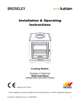
Assembly
When installing this appliance into a smoke control area you will need to change the clip
that is attached to the rear of the air slider for the smoke exempt clip (supplied). The
smoke exempt clip ensures a constant supply of combustion air to meet smoke exempt
requirements.
Some models will have a single
screw positioned to prevent the air
slider from fully closing, in non
smoke control zones this screw can
be removed to allow the air control
to fully close.

Evolution 26 MS10-11C Issue 4f 13
Plumbing Advice
Please read through the information given in “Important Information” (Page 3 of
these instructions) for the responsibilities and minimum requirements of the
installer. Please note any installations carried out by installers not meeting these
requirements will result in void product warranty and will not be supported by
Broseley Fires.
If connected to an unvented heating system, this appliance must (as a minimum) have the
following components installed on the system to ensure the safe operation of the
appliance. Please note these valves are NOT supplied as standard.
1) WATTS STS20 – Thermal discharge Valve
2) WATTS KSG 30 – Safety Pressure Relief Valve
3) Expansion Vessel comprising 7% of the total system volume
4) If connected in conjunction with a Gas Combination Boiler you will need a “Low Loss
Header” to link the boilers together; this will ensure that there is no conflict between the
two boilers. The low loss header should be sized and provided by the heating engineer.

Evolution 26 MS10-11C Issue 4f 14
Plumbing Advice
The eVolution 26 Stove differs from normal boiler stoves in the fact that it can be installed
on an open vented or sealed heating system. When installing the appliance on a sealed
system, it is necessary to install added safety features which allow the stove to be installed
safely. Our “SCWS Kit” can be purchased separately which contains the main valves
required.
DESCRIPTION OF SAFETY COLD WATER SYSTEM KIT
This is the minimum set of valves required for safe operation on a sealed system.
WATTS STS20 – Thermal discharge Valve
The STS20 prevents the boiler reaching
100°C. This works by transferring the heat in
the boiler away through a secondary quench
coil situated inside the boiler. The quench coil
is activated by a thermal safety valve (Watts
STS20) which activates at 97°C. The thermal
safety valve needs to be connected to mains
water and drained suitably through an outside
wall, in accordance with G3 regulations.
The Thermal Safety Valve needs to be connected to a mains water supply and then to the
quench coil in the boiler. Both openings are ¾ inch female connections. There should be a
minimum pressure of 1.5 bar mains water supply to the STS20. The maximum operating
pressure is 8 bar.
IF YOU CANNOT GUARANTEE A SUITABLE WORKING PRESSURE THEN THE
APPLIANCE SHOULD NOT BE INSTALLED
The discharge from the safety coil needs to be
discharged through an outside wall and terminated at
a low level within a 100mm through a metal pipe that
naturally drains. The discharge pipe should be in
accordance with G3 regulations. The thermal safety
valve probe needs to be inserted into the tube and ½
inch tapping in the rear of the boiler.
To ensure correct operation of the thermal safety drain over the
long-term, periodic drainage of the valve is required (at least once
a year); to perform such operation, press the red discharge
button located at the top of the valve head. Such operation allows
cleaning the seal seat where foreign particles build up. After a
certain number of periodic cleaning operations, it is advisable to
replace the valve plug which is supplied as spare part.

Evolution 26 MS10-11C Issue 4f 15
Plumbing Advice
WATTS KSG 30 – Safety Pressure Relief Valve
The KSG-30 acts as a final safety option in case of failure of the
STS20. This valve incorporates a 3bar pressure relief valve, a
pressure gauge and an automatic air vent. This must be placed
within 1 meter of the appliance.
N.B. the use of a quench coil does not affect the primary system volume and therefore
allows the system to recover and resume normal operation when the boiler has cooled
adequately. The use of the pressure blow off however will reduce the primary water
volume and drop the system pressure this will require the system to be refilled and
checked before it can be used again. Running a boiler without water in it can damage the
appliance and pumps allowed to run without water in them will quickly overheat and fail.
ESBE VTC511 - Back end Protection Valve
The back end protection is a three-way valve (regulated by
temperature) that improves the efficiency of the boiler, reduces
condensation and actively prolongs the longevity of the boiler. It
does this by not allowing cold water from the heating system to be
directly introduced into the boiler until a desired temperature is
reached, in this case 55°C.
The valve used is an ESBE VTC511 or equivalent.
Improves efficiency by not robbing heat from the fire.
Reduces boiler condensation and prolongs the life of the boiler by not allowing
water from condensation to mix with smoke particles potentially creating harmful
acids and toxins which can have detrimental effects on the boiler.
Helps reduce tarring inside the appliance and flue
Tarring may also result from burning wet wood with a moisture content greater than 20%

Evolution 26 MS10-11C Issue 4f 16
Plumbing Advice
Expansion vessels (not supplied)
The boiler must be directly connected to the expansion vessel in the system using a pipe
with a diameter no smaller than 18mm. The piping must not be obstructed in any way. The
expansion vessel must be at least 7% of volume of the total heating system. The
expansion vessel should be fitted on the suction side of the pump. The point at which it is
fitted is generally accepted as being the neutral point of the system. An expansion vessel
is divided into two compartments and separated by a flexible diaphragm. The sealed side
is charged with nitrogen gas. The open side is connected to the system.
Sizing of an expansion vessel:
Sizing of an expansion vessel is very important as the expansion vessel must be large
enough to accommodate all the expansion of the water.
The volume of water contained within the system. Manufacturers supply data which
includes water capabilities of such things as boilers and heat emitters.
Initial pressure of system, or pre-pressurisation, calculated from the static height
which is the vertical distance from the expansion vessel to the highest point.
The boiler flow temperature. Should the volume fall between two sizes, the larger
size must be used. The volume of the expansion vessel in litres fitted to a sealed
system shall not be less than that given by the table below.
Safety valve setting (bar)
3
Vessel charge pressure (bar)
0.5 1
1.5
Initial system pressure (bar) 0.5 1
1.5
2 1 1.5 2 1.5
2
Total water content of system
Expansion Vessel Volume (litres)
25 2.1 3.5 6.5 13.7 2.7 4.7 10.3 3.9 8.3
50 4.2 7 12.9 27.5 5.4 9.5 20.6 7.8 16.5
75 6.3 10.5 19.4 41.3 8.2 14.2 30.9 11.7 24.8
100 8.3 14 25.9 55.1 10.9 19 41.2 15.6 33.1
125
10.4 17.5 32.4 68.9 13.6 23.7 51.5 19.5 41.3
150 12.5 21 38.8 82.6 16.3 28.5 61.8 23.4 49.6
175 14.6 24.5 45.3 96.4 19.1 33.2 72.1 27.3 57.9
200 16.7 28 51.8 110.2 21.8 38 82.1 31.2 66.2
250 20.8 35 64.7 137.7 27.2 47.5 103 39 82.7
300 25 42 77.7 165.3 32.7 57 123.6 46.8 99.3
350 29.1 49 90.6 192.8 38.1 66.5 144.2 54.6 115.8
400 33.3 56 103.6 220.4 43.6 76 164.8 62.4 132.4
450 37.5 63 116.5 247.9 49 85.5 185.4 70.2 148.9
500 41.6 70 125.9 275.5 54.5 95 206 78 165.5

Evolution 26 MS10-11C Issue 4f 17
Plumbing Advice
Alarms
It is not a requirement to fit an alarm on the system, but it is recommended. The alarm will
act as a warning to the customer if the SCWS should operate. The alarm should be fitted
to the SCWS discharge pipe and should register an increase in temperature when the
SCWS is in operation. The customer should be notified that if this SCWS system/alarm is
continually operating that measures should be taken to stop the overheating of the
appliance. Measures to take are as follows:
1) Close all the air controls, including the tertiary and thermostatic air controls
2) Run hot water tap to remove some of the hot water in the cylinder (if fitted)
The customers should also be made aware that if there is constant operating of the
SCWS, they should contact the installer to diagnose any problems with the system.
N.B. A boiler that is too large for the required heat load will trigger the SCWS too often and
should therefore be replaced by a boiler that is better suited to the heating load.
It is mandatory to fit the safety components below when running a
closed/pressurised system. Failure to install these components will void your
guarantee and warranty, and risk the possibility of damage, to the extent of the
boiler exploding.
Table of required safety components
Safety Component
SCWS n/a Mandatory Mandatory
Safety Blow Off n/ a n/ a Mandatory
Back End Protection n/a Recommended Mandatory
Expansion Vessel n/ a n/ a Mandatory
Alarm n/a Recommended Recommended
Open Vented
– Gravity
Open Vented -
Pumped Pressurised

Evolution 26 MS10-11C Issue 4f 18
Plumbing Advice
Plumbing the Appliance – Open Vented
This installation should be in accordance with BS 5449:1990 - Specification for
forced circulation hot water central heating systems for domestic premises.
It must include a gravity circuit with an expansion tank open to the atmosphere.
When installing this appliance on a gravity circuit, the system should consist of a
tank/indirect cylinder fixed in an upright position and should be connected to the boiler by
28mm pipe (both flow and return). The pipes should not exceed 7.8m in length. The
shorter the run of pipe work the more effective the appliance is going to be at heating the
water. The cylinder and pipe work should be lagged to minimise the heat loss in the
system.
A ‘heat-leak’ radiator must be incorporated into the system to dissipate any excess heat
produced from the boiler when connected demands are low. The heat leak radiator must
be sized at a minimum of 10% the boiler output. Fit the heat leak radiator in the gravity
circuit using 22mm pipe reducing to 15mm for no more than 300mm before the radiator.
When plumbing the appliance open vented you will need to cap the SCWS discharge pipe
(D) but leave the SCWS flow uncapped (C) The SCWS probe hole will also need to be
capped (E) as it is not needed. (Letters refer to diagram on page 13).
Plumbing the appliance sealed/pressurised system
When installing the appliance on a closed/pressurised system the safety components
mentioned previously MUST be installed. Failure to do this could have very serious
consequences and will void your guarantee and warranty. We have given some examples
at the back of this plumbing advice on how the appliance can be installed in typical
situations. These illustrations should be taken as a guide and not a definitive plumbing
diagram. There is no requirement for a heat leak radiator on a closed system; we would
however recommend installing one radiator that has no thermostat.
Link Up Systems
It is possible to link the eVolution stove to other boilers on a pressurised/closed system.
This however can cause problems with ‘conflicts’ between the two boilers. Any solid fuel
appliance with a boiler can be linked to an existing or new central heating system fired by
another fuel or a second solid fuel appliance. This means that the central heating can be
heated by one or both boilers in tandem, depending on the heat demand.
When linking two or more heat sources together on a sealed system there are a number of
ways to do this, the easiest being via a low loss header.
A low loss header works on the same principals as a neutralizer on an open vented
system. It is a simple method to connect two appliances at a neutral point in order that
there is no hydraulic interaction between them. This means that the pumped circuit from a
second appliance will not induce a flow through the solid fuel boiler.

Evolution 26 MS10-11C Issue 4f 19
Plumbing Advice
Timer control of a system with a woodburning boiler appliance
As wood burning appliances are not automated, and can therefore not be ignited,
controlled and extinguished by electrical control from a heating programmer it needs to be
borne in mind that any heat produced when the heating is not being called for must be
able to be dissipated in order to negate unnecessary triggering of the safety devices.
The use of a thermostat on the low loss header that runs the CH pump (and opens the
appropriate motorised valves) when there is heat to be distributed is therefore necessary.
There should be provision made on the heating system to ensure that enough radiators (or
under floor heating zones) are permanently open and NOT thermostatically controlled to
allow at least 20% of the wood boilers nominal output.
In installations that only use a wood boiler and therefore have no low loss header a high
limit stat should be fitted to the flow from the boiler, set to ensure that the open circuit can
dissipate at least 20% of the nominal boiler output
Thermal Stores
An alternative way to link up different heat sources is through a Thermal Store; this can
link many appliances together and offers the best storage solution for any hot water
produced. Using a thermal store also allows for the option of linking in solar heating with
your system if required. Typical installation guides for link up systems can be found in the
diagrams at the back of this plumbing advvice section.
Checks on Initial Firing
Before connecting up the boiler, the installer must ensure that they thoroughly flush all of
the system’s pipes in order to remove any residue which could compromise the correct
operation of all system components (pumps, valves etc). It is also important to verify that
the chimney has sufficient draught, there are no blockages and that no other appliance
exhausts are inserted into the flue.
Inform the householder of the safety systems fitted to this stove. Explain the necessity to
maintain the water supply to the SCWS (cooling loop).
Filling up the System
Once all connections are complete, the installer can proceed with the boiler connection.
Open all the vent pipes of the radiators, the boiler and the system. Gradually open the load
valve, ensuring that the air vent pipes are working correctly. Use the gauge to confirm the
system is pressurised. With closed tank systems, a pressure of 0.11 – 0.12 MPa (1.1 – 1.2
bar) must be reached.

Evolution 26 MS10-11C Issue 4f 20
Plumbing Maintenance
It is essential that your stove is well maintained and annually serviced by a qualified
professional to ensure it's continued efficient operation. Failure to maintain and
service your appliance as laid out in these instructions will result in the voiding of
your products warranty. Please see section “Maintenance” for information on
annual servicing of the stove and its internal components.
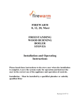
Plumbing Servicing
It is critical that all aspects of the SCWS (Safety Cold Water System) are annualy checked
to ensure correct operation. The main safety valve in the SCWS is the Watts STS20 valve,
which will open to allow mains cold water to enter the boilers quench coil. It is necessary to
clean the valve to remove impurities and deposits before initial firing and during servicing
of the installation. To activate the manual discharge and therefore the cleaning, press and
hold the red button on the valve, this will allow water to flow through the valve removing
the deposits. The manual test of this valve MUST be performed at the annual service.
Test Button
/