Agilent Technologies Satellite Radio 83430-90011 User manual
- Category
- Measuring, testing & control
- Type
- User manual
This manual is also suitable for

Agilent 83430A
Lightwave Transmitter
User’s Guide

ii
© Copyright 2000
Agilent Technologies
All Rights Reserved. Repro-
duction, adaptation, or trans-
lation without prior written
permission is prohibited,
except as allowed under copy-
right laws.
Agilent Part No. 83430-90011
Printed in USA
February 2000
Agilent Technologies
Lightwave Division
1400 Fountaingrove Parkway
Santa Rosa, CA 95403-1799,
USA
(707) 577-1400
Notice.
The information contained in
this document is subject to
change without notice. Com-
panies, names, and data used
in examples herein are ficti-
tious unless otherwise noted.
Agilent Technologies makes
no warranty of any kind with
regard to this material, includ-
ing but not limited to, the
implied warranties of mer-
chantability and fitness for a
particular purpose. Agilent
Technologies shall not be lia-
ble for errors contained herein
or for incidental or conse-
quential damages in connec-
tion with the furnishing,
performance, or use of this
material.
Restricted Rights Legend.
Use, duplication, or disclo-
sure by the U.S. Government
is subject to restrictions as set
forth in subparagraph (c) (1)
(ii) of the Rights in Technical
Data and Computer Software
clause at DFARS 252.227-7013
for DOD agencies, and sub-
paragraphs (c) (1) and (c) (2)
of the Commercial Computer
Software Restricted Rights
clause at FAR 52.227-19 for
other agencies.
Warranty.
This Agilent Technologies
instrument product is war-
ranted against defects in
material and workmanship for
a period of one year from date
of shipment. During the war-
ranty period, Agilent Technol-
ogies will, at its option, either
repair or replace products
which prove to be defective.
For warranty service or repair,
this product must be returned
to a service facility desig-
nated by Agilent Technolo-
gies. Buyer shall prepay
shipping charges to Agilent
Technologies and Agilent
Technologies shall pay ship-
ping charges to return the
product to Buyer. However,
Buyer shall pay all shipping
charges, duties, and taxes for
products returned to Agilent
Technologies from another
country.
Agilent Technologies war-
rants that its software and
firmware designated by Agi-
lent Technologies for use with
an instrument will execute its
programming instructions
when properly installed on
that instrument. Agilent Tech-
nologies does not warrant that
the operation of the instru-
ment, or software, or firmware
will be uninterrupted or error-
free.
Limitation of Warranty.
The foregoing warranty shall
not apply to defects resulting
from improper or inadequate
maintenance by Buyer, Buyer-
supplied software or interfac-
ing, unauthorized modifica-
tion or misuse, operation
outside of the environmental
specifications for the product,
or improper site preparation
or maintenance.
No other warranty is
expressed or implied. Agilent
Technologies specifically dis-
claims the implied warranties
of merchantability and fitness
for a particular purpose.
Exclusive Remedies.
The remedies provided herein
are buyer's sole and exclusive
remedies. Agilent Technolo-
gies shall not be liable for any
direct, indirect, special, inci-
dental, or consequential dam-
ages, whether based on
contract, tort, or any other
legal theory.
Safety Symbols.
CAUTION
The
caution
sign denotes a
hazard. It calls attention to a
procedure which, if not cor-
rectly performed or adhered
to, could result in damage to
or destruction of the product.
Do not proceed beyond a cau-
tion sign until the indicated
conditions are fully under-
stood and met.
WARNING
The
warning
sign denotes a
hazard. It calls attention to a
procedure which, if not cor-
rectly performed or adhered
to, could result in injury or
loss of life. Do not proceed
beyond a warning sign until
the indicated conditions are
fully understood and met.
The instruction man-
ual symbol. The prod-
uct is marked with this
warning symbol when
it is necessary for the
user to refer to the
instructions in the
manual.
The laser radiation
symbol. This warning
symbol is marked on
products which have a
laser output.
The AC symbol is used
to indicate the
required nature of the
line module input
power.
|
The ON symbols are
used to mark the posi-
tions of the instrument
power line switch.
❍
The OFF symbols
are used to mark the
positions of the instru-
ment power line
switch.
The CE mark is a reg-
istered trademark of
the European Commu-
nity.
The CSA mark is a reg-
istered trademark of
the Canadian Stan-
dards Association.
The C-Tick mark is a
registered trademark
of the Australian Spec-
trum Management
Agency.
This text denotes the
instrument is an
Industrial Scientific
and Medical Group 1
Class A product.
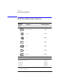
Typographical Conven-
tions.
The following conventions are
used in this book:
Key
type
for keys or text
located on the keyboard or
instrument.
Softkey
type
for key names that
are displayed on the instru-
ment’s screen.
Display
type
for words or
characters displayed on the
computer’s screen or instru-
ment’s display.
User
type
for words or charac-
ters that you type or enter.
Emphasis
type for words or
characters that emphasize
some point or that are used as
place holders for text that you
type.
ISM1-A

iii
The Agilent 83430A—At a Glance
The Agilent 83430A—At a Glance
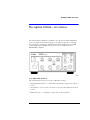
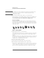
The Agilent 83430A lightwave transmitter is a directly modulated DFB laser
source for digital and analog testing up to 2.5 Gb/s. Designed for evaluating
the performance of high-speed TDM (time division multiplexed) and WDM
(wavelength division multiplexed) optical receivers and systems, it is
SDH/SONET compliant.
User Adjustable Features
The Agilent 83430A offers several user adjustable features:
• Digital input threshold — to obtain desired symmetry of optical one and zero
levels
• Wavelength — select a preset or tune to a specific value within ±1.25 nm of
center
• Extinction ratio — to simulate a wide range of optical signals

iv
The Agilent 83430A—At a Glance
Test Capabilities in Systems
The Agilent 83430A can be used as a general optical source or combined with
other instrumentation in systems to make a variety of measurements.
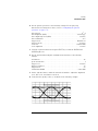
• Optical parametric tests — optical receiver sensitivity, dispersion power
penalty of single-mode fiber (with an Agilent 71603A error performance an-
alyzer and Agilent 83446A lightwave clock/data receiver).
• Transceiver waveform testing — including filtered conformance mask test-
ing, extinction ratio, and eye diagram measurements (with an
Agilent 83480A digital communications analyzer).
• Jitter tolerance of recovered clock and data — to determine the ability of a
receiver to maintain communication in the presence of jitter (with an
Agilent 71501C jitter and eye-diagram analyzer).
• Performance testing for WDM optical MUX/DEMUX channels — including
BER and system variations caused by cross-phase modulation and Raman
effect (with an Agilent 83446A lightwave clock/data receiver,
Agilent 71603B error performance analyzer, and Agilent 86120B multi-
wavelength meter).
For setup and procedures for these and other measurements, see Chapter 2,
“Making Measurements”.
Measurement accuracy—it’s up to you!
Fiber-optic connectors are easily damaged when connected to dirty or damaged cables
and accessories. The Agilent 83430A’s front-panel OPTICAL OUT connector is no excep-
tion. When you use improper cleaning and handling techniques, you risk expensive
instrument repairs, damaged cables, and compromised measurements.
Before you connect any fiber-optic cable to the Agilent 83430A, refer to “Cleaning Con-
nections for Accurate Measurements” on page 2-9.

v
The Agilent 83430A—At a Glance
Laser classification
The Agilent 83430A is classified as an IEC LASER Class 1. The total power of light
energy radiated out of the OPTICAL OUT connector is no greater than +8.1 dBm
(6.5 mW). Operator maintenance or precautions are not necessary to maintain safety. No
operator accessible controls, adjustments, or performance of procedures result in haz-
ardous radiation exposure.

vi
General Safety Considerations
General Safety Considerations
This product has been designed and tested in accordance with IEC Publica-
tion 61010-1, Safety Requirements for Electrical Equipment for Measurement,
Control and Laboratory Use, and has been supplied in a safe condition. The
instruction documentation contains information and warnings that must be
followed by the user to ensure safe operation and to maintain the product in a
safe condition.
WARNING
If this instrument is not used as specified, the protection provided by
the equipment could be impaired. This instrument must be used in a
normal condition (in which all means for protection are intact) only.
WARNING
To prevent electrical shock, disconnect the Agilent 83430A from
mains before cleaning. Use a dry cloth or one slightly dampened with
water to clean the external case parts. Do not attempt to clean
internally.
WARNING
This is a Safety Class 1 product (provided with a protective earthing
ground incorporated in the power cord). The mains plug shall only be
inserted in a socket outlet provided with a protective earth contact.
Any interruption of the protective conductor inside or outside of the
product is likely to make the product dangerous. Intentional
interruption is prohibited.
WARNING
No operator serviceable parts inside. Refer servicing to qualified
personnel. To prevent electrical shock, do not remove covers.
WARNING
For continued protection against fire hazard, replace line fuse only
with same type and ratings, (type T 0.315A/250V for 100/120V
operation and 0.16A/250V for 220/240V operation). The use of other
fuses or materials is prohibited. Verify that the value of the line-
voltage fuse is correct.
• For 100/120V operation, use an IEC 127 5
×
20 mm, 0.315 A, 250 V, Agilent
part number 2110-0449.
• For 220/240V operation, use an IEC 127 5
×
20 mm, 0.16 A, 250 V, Agilent
Technologies part number 2110-0448.

vii
General Safety Considerations
CAUTION
Before switching on this instrument, make sure that the line voltage selector
switch is set to the line voltage of the power supply and the correct fuse is
installed. Assure the supply voltage is in the specified range.
CAUTION
This product is designed for use in Installation Category II and Pollution
Degree 2 per IEC 1010 and 664 respectively.
CAUTION
VENTILATION REQUIREMENTS: When installing the product in a cabinet, the
convection into and out of the product must not be restricted. The ambient
temperature (outside the cabinet) must be less than the maximum operating
temperature of the product by 4
°
C for every 100 watts dissipated in the
cabinet. If the total power dissipated in the cabinet is greater than 800 watts,
then forced convection must be used.
CAUTION
Always use the three-prong ac power cord supplied with this instrument.
Failure to ensure adequate earth grounding by not using this cord may cause
instrument damage.
CAUTION
Do not
connect ac power until you have verified the line voltage is correct, refer
to “Line Power Requirements” on page 1-8. Damage to the equipment could
result.
CAUTION
This instrument has autoranging line voltage input. Be sure the supply voltage
is within the specified range.


Contents
Contents-1
The Agilent 83430A—At a Glance iii
1 Getting Started
Step 1. Inspect the Shipment 1-4
Step 2. Check the Fuse 1-6
Step 3. Connect the Line-Power Cable 1-8
Step 4. Turn on the Agilent 83430A 1-10
Returning the Instrument for Service 1-11
2 Making Measurements
Using the Agilent 83430A 2-3
Cleaning Connections for Accurate Measurements 2-9
3 Specifications and Regulatory Information
Specifications 3-3
Regulatory Information 3-6
4 Reference
Options 4-2
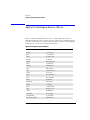
Front-Panel Fiber-Optic Adapters 4-4
Power Cords 4-5
Agilent Technologies Service Offices 4-6
5Servicing
General Information 5-4
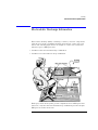
Electrostatic Discharge Information 5-7
Troubleshooting 5-9
Performance Tests 5-13
Adjustment Procedures 5-36


1-2
Getting Started
Getting Started
Getting Started
The instructions in this chapter show you how to install your Agilent 83430A.
You should be able to finish these procedures in about ten to twenty minutes.
After you’ve completed this chapter, continue with Chapter 2, “Making Mea-
surements”. Refer to Chapter 3, “Specifications and Regulatory Information”
for information on operating conditions such as temperature.
WARNING
To prevent electric shock, disconnect the Agilent 83430A from mains
before cleaning. Use a dry cloth or one slightly dampened with water
to clean the external case parts. Do not attempt to clean internally.
WARNING
This is a Safety Class 1 product (provided with a protective earthing
ground incorporated in the power cord). The mains plug shall only be
inserted in a socket outlet provided with a protective earth contact.
Any interruption of the protective conductor inside or outside of the
product is likely to make the product dangerous. Intentional
interruption is prohibited.
CAUTION
This product has autoranging line voltage input. Be sure the supply voltage is
within the specified range.
CAUTION
VENTILATION REQUIREMENTS: When installing the product in a cabinet, the
convection into and out of the product must not be restricted. The ambient
temperature (outside the cabinet) must be less than the maximum operating
temperature of the product by 4
°
C for every 100 watts dissipated in the
cabinet. If the total power dissipated in the cabinet is greater than 800 watts,
then forced convection must be used.
CAUTION
This product is designed for use in INSTALLATION CATEGORY II and
POLLUTION DEGREE 2, per IEC 1010 and 664 respectively.
CAUTION
Before switching on this instrument, make sure that the line voltage selector
switch is set to the line voltage of the power supply and the correct fuse is
installed. Assure the supply voltage is in the specified range.

1-3
Getting Started
Getting Started
Measurement accuracy—it’s up to you!
Fiber-optic connectors are easily damaged when connected to dirty or damaged cables
and accessories. The Agilent 83430A’s front-panel OPTICAL OUT connector is no excep-
tion. When you use improper cleaning and handling techniques, you risk expensive
instrument repairs, damaged cables, and compromised measurements.
Before you connect any fiber-optic cable to the Agilent 83430A, refer to “Cleaning Con-
nections for Accurate Measurements” on page 2-9.

1-4
Getting Started
Step 1. Inspect the Shipment
Step 1. Inspect the Shipment
1
Verify that all components ordered have arrived by comparing the shipping
forms to the original purchase order. Inspect all shipping containers.
If your shipment is damaged or incomplete, save the packing materials and
notify both the shipping carrier and the nearest Agilent Technologies service
office. Agilent Technologies will arrange for repair or replacement of
damaged or incomplete shipments without waiting for a settlement from the
transportation company. Notify the Agilent Technologies customer engineer
of any problems.
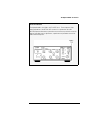
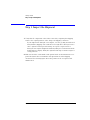
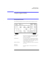
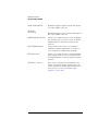
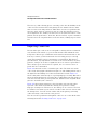
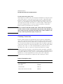
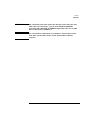
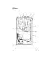
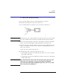
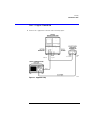
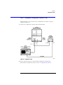
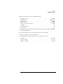
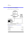
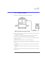
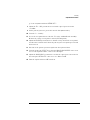
2
Make sure that the serial number and options listed on the instrument’s rear-
panel label match the serial number and options listed on the shipping
document. The following figure shows the position of the rear-panel serial
number label:

1-5
Getting Started
Step 1. Inspect the Shipment

1-6
Getting Started
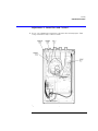
Step 2. Check the Fuse
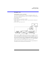
Step 2. Check the Fuse
CAUTION
Before connecting the lightwave receiver to the power source, you must set the
rear-panel voltage selector correctly to adapt the lightwave receiver to the
power source. An improper selector setting can damage the Agilent 83430A
when it is turned on.
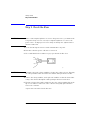
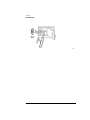
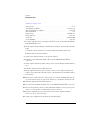
1
Locate the line-input connector on the instrument’s rear panel.
2
Disconnect the line-power cable if it is connected.
3
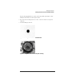
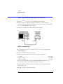
Use a small flat-blade screwdriver to pry open the fuse holder door.
CAUTION
You must remove the voltage tumbler to change the voltage selector. Rotating
the voltage tumbler while it is in the line module damages the line module.
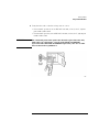
4
Remove the voltage tumbler, and replace the tumbler so that the desired line
voltage value shows through the small opening in the fuse holder door.
5
The fuse is housed in a small container next to the voltage tumbler. Insert the
tip of a screwdriver on the side of the container and gently pull outward to
remove the container.
A spare fuse is stored below the line fuse.

1-7
Getting Started
Step 2. Check the Fuse
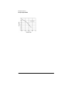
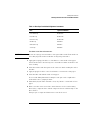
6
Verify that the value of the line-voltage fuse is correct.
• For 100/120V operation, use an IEC 127 5
×
20 mm, 0.315 A, 250 V, Agilent
part number 2110-0449.
• For 220/240V operation, use an IEC 127 5
×
20 mm, 0.16 A, 250 V, Agilent part
number 2110-0448.
WARNING
For continued protection against fire hazard, replace line fuse only
with same type and ratings, (type T 0.315A/250V for 100/120V
operation and 0.16A/250V for 220/240V operation). The use of other
fuses or materials is prohibited.

1-8
Getting Started
Step 3. Connect the Line-Power Cable
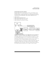
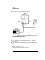
Step 3. Connect the Line-Power Cable
CAUTION
Always use the three-prong AC power cord supplied with this instrument.
Failure to ensure adequate earth grounding by not using this cord may cause
instrument damage.
CAUTION
Do
not
connect ac power until you have verified the line voltage is correct as
described in the following paragraphs. Damage to the equipment could result.
CAUTION
This instrument has autoranging line voltage input. Be sure the supply voltage
is within the specified range.
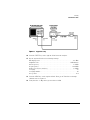
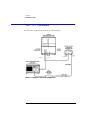
1
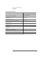
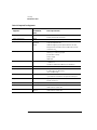
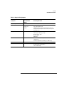
Verify that the line power meets the requirements shown in the following table.
2
Connect the line-power cord to the instrument’s rear-panel connector.
Line Power Requirements
Power 115 VAC: 50 WATTS MAX
230 VAC: 50 WATTS MAX
Voltage nominal: 115 VAC range:90–132 V
nominal:230 VACrange:98–254 V
Frequency nominal: 50 Hz/60 Hzrange: 47–63 Hz

1-9
Getting Started
Step 3. Connect the Line-Power Cable
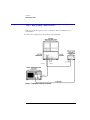
3
Connect the other end of the line-power cord to the power receptacle.
Various power cables are available to connect the Agilent 83430A to ac power
outlets unique to specific geographic areas. The cable appropriate for the area
to which the Agilent 83430A is originally shipped is included with the unit. You
can order additional ac power cables for use in different geographic areas.
Refer to “Power Cords” on page 4-5.

1-10
Getting Started
Step 4. Turn on the Agilent 83430A
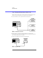
Step 4. Turn on the Agilent 83430A
• Press the front-panel
LINE
key.
The front-panel
LINE
switch disconnects the mains circuits from the mains sup-
ply after the EMC filters and before other parts of the instrument.
If the Agilent 83430A fails to turn on properly, consider the following possibili-
ties:
❒
Is the line fuse good?
❒
Does the line socket have power?
❒
Is it plugged into the proper ac power source?
If the instrument still fails, return it to Agilent Technologies for repair. Refer to
“Returning the Instrument for Service” on page 1-11.
Page is loading ...
Page is loading ...
Page is loading ...
Page is loading ...
Page is loading ...
Page is loading ...
Page is loading ...
Page is loading ...
Page is loading ...
Page is loading ...
Page is loading ...
Page is loading ...
Page is loading ...
Page is loading ...
Page is loading ...
Page is loading ...
Page is loading ...
Page is loading ...
Page is loading ...
Page is loading ...
Page is loading ...
Page is loading ...
Page is loading ...
Page is loading ...
Page is loading ...
Page is loading ...
Page is loading ...
Page is loading ...
Page is loading ...
Page is loading ...
Page is loading ...
Page is loading ...
Page is loading ...
Page is loading ...
Page is loading ...
Page is loading ...
Page is loading ...
Page is loading ...
Page is loading ...
Page is loading ...
Page is loading ...
Page is loading ...
Page is loading ...
Page is loading ...
Page is loading ...
Page is loading ...
Page is loading ...
Page is loading ...
Page is loading ...
Page is loading ...
Page is loading ...
Page is loading ...
Page is loading ...
Page is loading ...
Page is loading ...
Page is loading ...
Page is loading ...
Page is loading ...
Page is loading ...
Page is loading ...
Page is loading ...
Page is loading ...
Page is loading ...
Page is loading ...
Page is loading ...
Page is loading ...
Page is loading ...
Page is loading ...
Page is loading ...
Page is loading ...
Page is loading ...
Page is loading ...
Page is loading ...
Page is loading ...
Page is loading ...
Page is loading ...
Page is loading ...
Page is loading ...
Page is loading ...
Page is loading ...
Page is loading ...
Page is loading ...
Page is loading ...
Page is loading ...
Page is loading ...
Page is loading ...
-
 1
1
-
 2
2
-
 3
3
-
 4
4
-
 5
5
-
 6
6
-
 7
7
-
 8
8
-
 9
9
-
 10
10
-
 11
11
-
 12
12
-
 13
13
-
 14
14
-
 15
15
-
 16
16
-
 17
17
-
 18
18
-
 19
19
-
 20
20
-
 21
21
-
 22
22
-
 23
23
-
 24
24
-
 25
25
-
 26
26
-
 27
27
-
 28
28
-
 29
29
-
 30
30
-
 31
31
-
 32
32
-
 33
33
-
 34
34
-
 35
35
-
 36
36
-
 37
37
-
 38
38
-
 39
39
-
 40
40
-
 41
41
-
 42
42
-
 43
43
-
 44
44
-
 45
45
-
 46
46
-
 47
47
-
 48
48
-
 49
49
-
 50
50
-
 51
51
-
 52
52
-
 53
53
-
 54
54
-
 55
55
-
 56
56
-
 57
57
-
 58
58
-
 59
59
-
 60
60
-
 61
61
-
 62
62
-
 63
63
-
 64
64
-
 65
65
-
 66
66
-
 67
67
-
 68
68
-
 69
69
-
 70
70
-
 71
71
-
 72
72
-
 73
73
-
 74
74
-
 75
75
-
 76
76
-
 77
77
-
 78
78
-
 79
79
-
 80
80
-
 81
81
-
 82
82
-
 83
83
-
 84
84
-
 85
85
-
 86
86
-
 87
87
-
 88
88
-
 89
89
-
 90
90
-
 91
91
-
 92
92
-
 93
93
-
 94
94
-
 95
95
-
 96
96
-
 97
97
-
 98
98
-
 99
99
-
 100
100
-
 101
101
-
 102
102
-
 103
103
-
 104
104
-
 105
105
-
 106
106


Agilent Technologies Satellite Radio 83430-90011 User manual
- Category
- Measuring, testing & control
- Type
- User manual
- This manual is also suitable for
Ask a question and I''ll find the answer in the document
Finding information in a document is now easier with AI
Related papers
-
Agilent Technologies B User manual
-
-
-
-
-
-
-
-
-
Other documents
-
Hans Grohe 42134XX0 User manual
-
-
Keysight Technologies 86120B User manual
-
-
Finisar FTLX3815M3XX Datasheet
-
Keysight N4906B Serial BERT Quick start guide
-
V7 V7E-625LCLC-03M Datasheet
-
-
Aiphone IX-SDH Install Manual
-
Grundig PS 8710 Datasheet