Page is loading ...

AMI Sodium P
Version 6.00 and higher
A-96.250.211 / 200416
Operator’
s Manual

© 2016, SWAN ANALYTISCHE INSTRUMENTE AG, Switzerland, all rights reserved
subject to change without notice
Customer Support
SWAN and its representatives maintain a fully trained staff of technical specialists
around the world. For any technical question, contact your nearest
SWAN representative, or the manufacturer:
SWAN ANALYTISCHE INSTRUMENTE AG
Studbachstrasse 13
8340 Hinwil
Switzerland
Internet: www.swan.ch
E-mail: [email protected]
Document Status
Title:
Monitor AMI Sodium P Operator’s Manual
ID:
A-96.250.211
Revision Issue
00 April 2005 First edition
04 October 2011 Update to Firmware Release 4.50
05 April 2014 Main board V2.4, Update to Firmware Release 5.40
06 April 2016 Main board V2.5, Update to Firmware Release 6.00

AMI Sodium P
A-96.250.211 / 200416 1
Table of Contents
1. Safety Instructions . . . . . . . . . . . . . . . . . . . . . . . . . . . . . . . . . . . 4
1.1. Warning Notices . . . . . . . . . . . . . . . . . . . . . . . . . . . . . . . . . . . . . . 5
1.2. General Safety Regulations . . . . . . . . . . . . . . . . . . . . . . . . . . . . . 7
1.3. Restrictions for use. . . . . . . . . . . . . . . . . . . . . . . . . . . . . . . . . . . . 8
2. Product Description . . . . . . . . . . . . . . . . . . . . . . . . . . . . . . . . . . 9
2.1. Instrument Specification . . . . . . . . . . . . . . . . . . . . . . . . . . . . . . . . 13
2.2. Instrument Overview. . . . . . . . . . . . . . . . . . . . . . . . . . . . . . . . . . . 16
3. Installation. . . . . . . . . . . . . . . . . . . . . . . . . . . . . . . . . . . . . . . . . . 17
3.1. Installation Check List. . . . . . . . . . . . . . . . . . . . . . . . . . . . . . . . . . 17
3.2. Mounting of Instrument Panel. . . . . . . . . . . . . . . . . . . . . . . . . . . . 18
3.3. Connect Sample and Waste. . . . . . . . . . . . . . . . . . . . . . . . . . . . . 19
3.3.1 FEP Tube at Sample Inlet . . . . . . . . . . . . . . . . . . . . . . . . . . . . . 19
3.3.2 Sample Outlet . . . . . . . . . . . . . . . . . . . . . . . . . . . . . . . . . . . . . . 19
3.4. Install Sensors . . . . . . . . . . . . . . . . . . . . . . . . . . . . . . . . . . . . . . . 20
3.4.1 Install the Sodium Electrode . . . . . . . . . . . . . . . . . . . . . . . . . . . 21
3.4.2 Install the Reference Electrode . . . . . . . . . . . . . . . . . . . . . . . . . 23
3.4.3 Install the pH Electrode . . . . . . . . . . . . . . . . . . . . . . . . . . . . . . . 27
3.4.4 Install the Temperature Sensor. . . . . . . . . . . . . . . . . . . . . . . . . 28
3.4.5 Install reagent bottle . . . . . . . . . . . . . . . . . . . . . . . . . . . . . . . . . 28
3.5. Install 2nd Sample Stream (Option) . . . . . . . . . . . . . . . . . . . . . . . 29
3.5.1 Connect the solenoid valve . . . . . . . . . . . . . . . . . . . . . . . . . . . . 30
3.5.2 Firmware settings for 2nd sample stream option . . . . . . . . . . . 31
3.6. AMI Sodium P connected to a Sample Sequencer . . . . . . . . . . . 32
3.7. Electrical Connections . . . . . . . . . . . . . . . . . . . . . . . . . . . . . . . . . 33
3.7.1 Connection Diagram . . . . . . . . . . . . . . . . . . . . . . . . . . . . . . . . . 35
3.8. Relay Contacts . . . . . . . . . . . . . . . . . . . . . . . . . . . . . . . . . . . . . . . 37
3.8.1 Input . . . . . . . . . . . . . . . . . . . . . . . . . . . . . . . . . . . . . . . . . . . . . 37
3.8.2 Alarm Relay. . . . . . . . . . . . . . . . . . . . . . . . . . . . . . . . . . . . . . . . 37
3.8.3 Relay 1 and 2 . . . . . . . . . . . . . . . . . . . . . . . . . . . . . . . . . . . . . . 38
3.9. Signal Outputs . . . . . . . . . . . . . . . . . . . . . . . . . . . . . . . . . . . . . . . 40
3.9.1 Signal Output 1 and 2 (current outputs) . . . . . . . . . . . . . . . . . . 40
3.10. Interface Options . . . . . . . . . . . . . . . . . . . . . . . . . . . . . . . . . . . . . 40
3.10.1 Signal Output 3 . . . . . . . . . . . . . . . . . . . . . . . . . . . . . . . . . . . . . 41
3.10.2 Profibus, Modbus Interface . . . . . . . . . . . . . . . . . . . . . . . . . . . . 42
3.10.3 USB Interface . . . . . . . . . . . . . . . . . . . . . . . . . . . . . . . . . . . . . . 42
3.11. Connection of Sensors . . . . . . . . . . . . . . . . . . . . . . . . . . . . . . . . . 43

2 A-96.250.211 / 200416
AMI Sodium P
4. Instrument Setup . . . . . . . . . . . . . . . . . . . . . . . . . . . . . . . . . . . . 44
4.1. Install Reagent Bottle . . . . . . . . . . . . . . . . . . . . . . . . . . . . . . . . . . 44
4.2. Establish Sample Flow . . . . . . . . . . . . . . . . . . . . . . . . . . . . . . . . . 45
4.3. Switch on Power . . . . . . . . . . . . . . . . . . . . . . . . . . . . . . . . . . . . . . 46
4.4. Programming . . . . . . . . . . . . . . . . . . . . . . . . . . . . . . . . . . . . . . . . 46
4.5. Check Outputs and Relays . . . . . . . . . . . . . . . . . . . . . . . . . . . . . . 46
4.6. Perform a calibration. . . . . . . . . . . . . . . . . . . . . . . . . . . . . . . . . . . 46
5. Operation. . . . . . . . . . . . . . . . . . . . . . . . . . . . . . . . . . . . . . . . . . . 47
5.1. Keys, Display . . . . . . . . . . . . . . . . . . . . . . . . . . . . . . . . . . . . . . . . 47
5.2. Software Structure . . . . . . . . . . . . . . . . . . . . . . . . . . . . . . . . . . . . 49
5.3. Changing Parameters and Values . . . . . . . . . . . . . . . . . . . . . . . . 50
5.4. Grab Sample. . . . . . . . . . . . . . . . . . . . . . . . . . . . . . . . . . . . . . . . . 51
6. Maintenance . . . . . . . . . . . . . . . . . . . . . . . . . . . . . . . . . . . . . . . . 52
6.1. Maintenance Schedule . . . . . . . . . . . . . . . . . . . . . . . . . . . . . . . . . 52
6.2. Stop of Operation for Maintenance. . . . . . . . . . . . . . . . . . . . . . . . 52
6.3. Maintenance of Sodium Electrode . . . . . . . . . . . . . . . . . . . . . . . . 53
6.4. Maintenance of Reference Electrode . . . . . . . . . . . . . . . . . . . . . . 55
6.5. Maintenance of pH Sensor . . . . . . . . . . . . . . . . . . . . . . . . . . . . . . 56
6.6. Maintenance of Solenoid Valve . . . . . . . . . . . . . . . . . . . . . . . . . . 57
6.7. Maintenance of Flow Cell and Constant Head . . . . . . . . . . . . . . . 59
6.7.1 Cleaning the Flow cell . . . . . . . . . . . . . . . . . . . . . . . . . . . . . . . . 60
6.7.2 Cleaning the Constant Head . . . . . . . . . . . . . . . . . . . . . . . . . . . 61
6.8. Replace the Air Filter . . . . . . . . . . . . . . . . . . . . . . . . . . . . . . . . . . 63
6.9. Prepare Standard . . . . . . . . . . . . . . . . . . . . . . . . . . . . . . . . . . . . . 64
6.10. Calibration. . . . . . . . . . . . . . . . . . . . . . . . . . . . . . . . . . . . . . . . . . . 64
6.10.1 pH Process Calibration . . . . . . . . . . . . . . . . . . . . . . . . . . . . . . . 64
6.10.2 Standard Sodium 1-Point-Calibration . . . . . . . . . . . . . . . . . . . . 65
6.10.3 2-Point-Calibration. . . . . . . . . . . . . . . . . . . . . . . . . . . . . . . . . . . 67
6.11. Tube Replacement . . . . . . . . . . . . . . . . . . . . . . . . . . . . . . . . . . . . 68
6.11.1 Tube Numbering . . . . . . . . . . . . . . . . . . . . . . . . . . . . . . . . . . . . 68
6.11.2 Replace the Reaction Tube. . . . . . . . . . . . . . . . . . . . . . . . . . . . 69
6.11.3 Replace the EPDM Seal and the Air Inlet Tube . . . . . . . . . . . . 70
6.12. Replacing Fuses . . . . . . . . . . . . . . . . . . . . . . . . . . . . . . . . . . . . . . 71
6.13. Longer Stop of Operation . . . . . . . . . . . . . . . . . . . . . . . . . . . . . . . 72

AMI Sodium P
A-96.250.211 / 200416 3
7. Error List . . . . . . . . . . . . . . . . . . . . . . . . . . . . . . . . . . . . . . . . . . . 73
8. Program Overview . . . . . . . . . . . . . . . . . . . . . . . . . . . . . . . . . . . 76
8.1. Messages (Main Menu 1) . . . . . . . . . . . . . . . . . . . . . . . . . . . . . . . 76
8.2. Diagnostics (Main Menu 2). . . . . . . . . . . . . . . . . . . . . . . . . . . . . . 77
8.3. Maintenance (Main Menu 3). . . . . . . . . . . . . . . . . . . . . . . . . . . . . 78
8.4. Operation (Main Menu 4) . . . . . . . . . . . . . . . . . . . . . . . . . . . . . . . 79
8.5. Installation (Main Menu 5) . . . . . . . . . . . . . . . . . . . . . . . . . . . . . . 79
9. Program List and Explanations. . . . . . . . . . . . . . . . . . . . . . . . . 81
1 Messages . . . . . . . . . . . . . . . . . . . . . . . . . . . . . . . . . . . . . . . . . 81
2 Diagnostics . . . . . . . . . . . . . . . . . . . . . . . . . . . . . . . . . . . . . . . . 81
3 Maintenance . . . . . . . . . . . . . . . . . . . . . . . . . . . . . . . . . . . . . . . 83
4 Operation. . . . . . . . . . . . . . . . . . . . . . . . . . . . . . . . . . . . . . . . . . 84
5 Installation . . . . . . . . . . . . . . . . . . . . . . . . . . . . . . . . . . . . . . . . . 85
10. Material Safety Data Sheet. . . . . . . . . . . . . . . . . . . . . . . . . . . . . 101
10.1. Reagents . . . . . . . . . . . . . . . . . . . . . . . . . . . . . . . . . . . . . . . . . . . 101
11. Default Values. . . . . . . . . . . . . . . . . . . . . . . . . . . . . . . . . . . . . . . 102
12. Index . . . . . . . . . . . . . . . . . . . . . . . . . . . . . . . . . . . . . . . . . . . . . . 105
13. Notes . . . . . . . . . . . . . . . . . . . . . . . . . . . . . . . . . . . . . . . . . . . . . . 107

4 A-96.250.211 / 200416
AMI Sodium P
Safety Instructions
AMI Sodium P - Operator’s Manual
This document describes the main steps for instrument setup, oper-
ation and maintenance.
1. Safety Instructions
General The instructions included in this section explain the potential risks
associated with instrument operation and provide important safety
practices designed to minimize these risks.
If you carefully follow the information contained in this section, you
can protect yourself from hazards and create a safer work environ-
ment.
More safety instructions are given throughout this manual, at the
respective locations where observation is most important.
Strictly follow all safety instructions in this publication.
Target
audience
Operator: Qualified person who uses the equipment
for its intended purpose.
Instrument operation requires thorough knowledge of applications,
instrument functions and software program as well as all applicable
safety rules and regulations.
OM Location The AMI Operator’s Manual shall be kept in proximity of the instru-
ment.
Qualification,
Training
To be qualified for instrument installation and operation, you must:
read and understand the instructions in this manual as well as
the Material Safety Data Sheets.
know the relevant safety rules and regulations.

AMI Sodium P
Safety Instructions
A-96.250.211 / 200416 5
1.1. Warning Notices
The symbols used for safety-related notices have the following sig-
nificance:
DANGER
Your life or physical wellbeing are in serious danger if such
warnings are ignored.
Follow the prevention instructions carefully.
WARNING
Severe injuries or damage to the equipment can occur if such
warnings are ignored.
Follow the prevention instructions carefully.
CAUTION
Damage to the equipment, minor injury, malfunctions or incor-
rect process can be the consequence if such warnings are ig-
nored.
Follow the prevention instructions carefully.
Mandatory
Signs
The importance of the mandatory signs in this manual.
Safety goggles
Safety gloves

6 A-96.250.211 / 200416
AMI Sodium P
Safety Instructions
Warning Signs The importance of the warning signs in this manual.
Electrical shock hazard
Corrosive
Harmful to health
Flammable
Warning general
Attention general

AMI Sodium P
Safety Instructions
A-96.250.211 / 200416 7
1.2. General Safety Regulations
Legal
Requirements
The user is responsible for proper system operation.
All precautions must be followed to ensure safe operation
of the instrument.
Spare Parts
and
Disposables
Use only official SWAN spare parts and disposables. If other parts
are used during the normal warranty period, the manufacturer’s
warranty is voided.
Modifications Modifications and instrument upgrades shall only be carried out by
an authorized Service Technician. SWAN will not accept responsi-
bility for any claim resulting from unauthorized modification or alter-
ation.
WARNING
Risk of Electrical Shock
If proper operation is no longer possible, the instrument must be
disconnected from all power lines, and measures must be taken
to prevent inadvertent operation.
To prevent from electrical shock, always make sure that the
ground wire is connected.
Service shall be performed by authorized personnel only.
Whenever electronic service is required, disconnect instru-
ment power and power of devices connected to.
– relay 1,
– relay 2,
– alarm relay
WARNING
For safe instrument installation and operation you must read
and understand the instructions in this manual.
WARNING
Only SWAN trained and authorized personnel shall perform the
tasks described in this document.

8 A-96.250.211 / 200416
AMI Sodium P
Safety Instructions
1.3. Restrictions for use
The sample must not contain any particles, which may block the
flow cell. Sufficient sample flow is coercive for the correct function
of the instrument.
This instrument is only applicable to waters of a pH value higher
than 7.
WARNING
For safe instrument installation and operation you must read
and understand the instructions in this manual, as well as the
Material Safety Data Sheets (MSDS)
Etching kit for sodium electrode (powder + liquid)
Sodium calibration solution
Electrolyte for reference electrode
Alcalizing reagent (e. g. Diisopropylamine)
Only SWAN trained and authorized personnel shall perform the
tasks described in this document.
Download
MSDS
The current Material Safety Data Sheets (MSDS) for the below list-
ed Reagents are available for downloading at www.swan.ch.

AMI Sodium P
Product Description
A-96.250.211 / 200416 9
2. Product Description
Application Sodium measurement is used for quality control in high purity water
applications and to monitor break through of mixed bed ion ex-
changers, condenser leaks and the prevention of caustic corrosion
of turbines. The AMI Sodium P is suitable for samples with a pH
value higher than pH7. For samples with a pH lower than pH7, use
the AMI Sodium A.
Measuring
principle
The sodium measurement used in this instrument is based on a po-
tentiometric measuring method. For this purpose a proven sodium
ion sensitive glass electrode and a reference electrode is used.
These two electrodes produce a different electrical potential which
is used to calculate the sodium concentration of the sample. Ac-
cording to Nernsts Law, the ion concentration depends on the tem-
perature, therefore a temperature sensor measures the sample
temperature. With the current temperature the measuring value is
expressed for the standard temperature of 25 °C by using pro-
grammed temperature compensation curves.
Sodium measurements below 1 ppb require a special glass formu-
lation for the sensing electrode response.
Ammonium and pH interferences from the unconditioned sample
are eliminated by a suitable reagent. The measuring limit of 0.1 ppb
sodium requires the conditioning of the sample to a minimum of
pH 10.5 while sample integrity has to be maintained. The best re-
sults are obtained with Diisopropylamine (DIPA).
Signal
Outputs
Two signal outputs programmable for measured values (freely scal-
able, linear or bilinear) or as continuous control output (control pa-
rameters programmable).
Current loop: 0/4 - 20 mA
Maximal burden: 510
Third signal output available as an option.
Relay Two potential-free contacts programmable as limit switches for
measuring values, controllers or timer for system cleaning with au-
tomatic hold function.
Maximum load: 1 A / 250 VAC

10 A-96.250.211 / 200416
AMI Sodium P
Product Description
Alarm Relay One potential free contact. Alternatively:
Open during normal operation, closed on error and loss of
power.
Closed during normal operation, open on error and loss of
power.
Summary alarm indication for programmable alarm values and in-
strument faults.
Input For potential-free contact to freeze the measuring value or to inter-
rupt control in automated installations (hold function or remote-off).
Safety
Features
No data loss after power failure. All data is saved in non-volatile
memory. Over voltage protection of in- and outputs.Galvanic sepa-
ration of measuring inputs and signal outputs.The analyzer is facto-
ry tested and ready for installation and operation.
Communica-
tion Interface
(optional)
USB Interface for logger download.
RS485 Interface with Fieldbus protocol Modbus or Profibus DP.
Consumables The filling of the 100 ml KCl Bottle lasts for one month of operation.
On-line
Operation
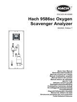
The sample flows via the sample inlet [D] and the flow regulating
valve [C] into the constant head [A]. Adjust the flow regulating valve
so that always a small part of the sample flows through the overflow
tube [M] into the waste. This adjustment ensures a sufficient sam-
ple flow through the flow cell [K]. First the sample flows into the
measuring chamber [K
1
] where the sodium electrode [G] is installed
and the sodium concentration of the sample is measured. From
there it flows into the measuring chamber [K
2
] where the pH elec-
trode [F], the temperature sensor [H] and the reference electrode
[E] are installed and thereafter it flows via flow cell [K
3
] through the
sample outlet [L].
During on-line operation, the standard bottle holder [Q] is complete-
ly turned down, and the sample flows from the constant head [A]
into the reaction tube [B].
Due to the different level of the constant head and the flow cell, a
negative pressure is created in the reaction tube [B]. As a result, re-
agent saturated air is sucked into the reaction tube, raising the pH
of the sample to a value of 10.5, and forming a regular stream of air
bubbles [J].
The bubble stream is used to monitor the correct sample flow with
the bubble detector [I]. An inconsistent sample flow causes an in-
terruption of the bubble formation and produces a system error.

AMI Sodium P
Product Description
A-96.250.211 / 200416 11
Fluidics
A
B
C
D
E
F
G
H
I
J
Constant head
Reaction tube
Flow regulating valve
Sample inlet
Reference electrode
pH electrode
Sodium electrode
Temperature sensor
Bubble counter
Sample with air bubbles
K
L
M
N
O
P
Q
R
S
Flow cell
Sample outlet
Overflow tube
Air inlet filter
Air tube to DIPA bottle
Tube with DIPA saturated air
Standard bottle holder
Reagent bottle
Flow cell top view
A
B
C
D
E
E
F
F
G
G
H
H
I
J
L
M
K
K
1
K
2
K
3
N
O
P
R
S
Q

12 A-96.250.211 / 200416
AMI Sodium P
Product Description
Second
Sample Stream
If required the AMI Sodium P can be equipped with the optional
second sample stream module. To install the 2nd sample stream
option a AMI Sodium P with 400 mm panel with is required.
Sample
Sequencer
If measurement of more than two sample streams is required, the
AMI Sodium P can be connected to a Sample Sequencer which al-
lows to measure up to six sample streams.
Grab Sample The standard bottle holder can also be used for a grab sample
measurement. Grab sample measurement see Grab Sample, p.
51.
Calibration A standard bottle is screwed in the standard bottle holder [Q] and
turned upwards into the vertical position, thus switching the sample
flow from the constant head to the standard bottle. Constant pres-
sure within the standard bottle is maintained by the pressure-equal-
izing tube inside the bottle.
1 liter standard is consumed in approx. 10 min. The sodium elec-
trode must reach constant readings within this time to obtain an ex-
act calibration.
For details, see Calibration, p. 42.

AMI Sodium P
Product Description
A-96.250.211 / 200416 13
2.1. Instrument Specification
Power Supply Voltage:
Power consumption:
100–240 VAC (± 10%)
50/60 Hz (± 5%)
or 24 VDC (± 10%)
max. 30 VA
Electronics Aluminium with a protection degree of IP 66 / NEMA 4X
housing Ambient temperature:
Limit range of operation:
Storage and transport:
Humidity:
Display:
-10 to +50 °C
-25 to +65 °C
-30 to +85 °C
10–90% rel., non condensing
backlit LCD, 75 x 45 mm
Sample
requirements
pH Value:
Ammonium concentration:
Flow rate:
Temperature:
Inlet pressure:
Outlet pressure:
pH 7.0
< 10 ppm
min. 100 ml/min.
5–45 °C (41–113 °F)
0.3–3 bar (4–43 PSI)
pressure free
NOTICE: No oil, no grease, no sand.
On-site The analyzer site must permit connections to:
requirements Sample inlet:
Sample outlet:
Max. Altitude:
Tube 4 x 6 mm
1/2” hose nozzle for flexible tube diam.
20x15 mm
2000 m above sea level

14 A-96.250.211 / 200416
AMI Sodium P
Product Description
Dimensions: Panel:
Mounting hole distance:
Screws:
Weight:
280 x 850 x 200 mm
254 x 824 mm
8 mm diameter
9.0 kg / 19.85 lbs without sample water
Exit Enter
824 mm / 32
7
/
16
”
850 mm / 33½”
13 mm / ½”
280 mm / 11”
254 mm / 10”
13 mm / ½”
4 x dia. 10 mm
3
/
8
”

AMI Sodium P
Product Description
A-96.250.211 / 200416 15
Dimensions
with 2nd
sample stream
Panel:
Mounting hole distance:
Screws:
Weight:
400 x 850 x 200 mm
374 x 824 mm
8 mm diameter
12.0 kg / 26.5 lbs without sample water
Exit Enter
824 mm / 32
7
/
16
”
850 mm / 33½”
13 mm / ½”
400 mm / 11”
374 mm / 10”
13 mm / ½”
4 x dia. 10 mm
3
/
8
”

16 A-96.250.211 / 200416
AMI Sodium P
Product Description
2.2. Instrument Overview
A
B
C
D
E
F
G
H
I
Transmitter
Panel
Reference electrolyte bottle
2
nd
sample stream (option)
Flow regulating valve
Sample inlet
pH electrode
Sodium electrode
Bubble detector
J
K
L
M
N
O
P
Q
Air filter
Constant head
Standard bottle/Grab sample
Standard bottle holder
Reference electrode
Temperature sensor
Reagent bottle
Sample outlet
A
J
K
L
M
N
O
P
Q
B
C
D
E
F
G
H
I

AMI Sodium P
Installation
A-96.250.211 / 200416 17
3. Installation
3.1. Installation Check List
Check Instrument’s specification must conform to the National Electrical
Code, all state and local codes, and all plant codes and standards
for electrical equipment.
On site require-
ments
100 - 240 VAC ( 10%), 50/60 Hz ( 5%) or 24 VDC, isolated
(±10%) power outlet with ground connection and 30 VA
Sample line with min. 100 ml/min and 0.3–3.0 bar (4–43 psi)
Waste line with pressure free drain.
See Connecting Sample and Waste, p. 21.
Installation Install the instrument in vertical position.
Display should be at eye-level.
Connect the sample and waste line(s).
See Connecting Sample and Waste, p. 21
Electrodes Sodium electrode: Install the Sodium Electrode, p. 21.
Etch the sodium electrode
Rinse it well and check for air bubbles inside the electrode.
Install the sodium electrode.
Connect cable S to the sodium electrode.
Reference electrode: Install the Reference Electrode, p. 23.
Install KCl bottle,
Check the ground joint diaphragm
Install the reference electrode.
Puncture the KCl bottle.
Connect cable R to the reference electrode.
pH electrode: Install the pH Electrode, p. 27.
Install the pH electrode.
Connect cable pH to the pH electrode
Reagent and
filter connec-
tions
We recommend to use DIPA to operate the instrument. Use a
reagent bottle with either G45 thread (Schott) or a bottle from
Merck using a thread adapter. Close the bottle well to prevent the
formation of reagent vapors. For installation see Install Reagent
Bottle, p. 44.
Install the air filter.

18 A-96.250.211 / 200416
AMI Sodium P
Installation
3.2. Mounting of Instrument Panel
The first part of this chapter describes the preparing and placing of
the instrument for use.
The instrument must only be installed by trained personnel.
Mount the instrument in vertical position.
For ease of operation mount it so that the display is at eye
level.
For the installation a kit containing the following installation
material is available:
– 4 Screws 8x60 mm
– 4 Dowels
– 4 Washers 8.4/24 mm
Mounting re-
quirements
The instrument is only intended for indoor installation.
For dimensions see Dimensions:, p. 14 or Dimensions with 2nd
sample stream, p. 15.
Electrical Wiring
NOTICE: Do not switch on the Instrument until all electrical
connections are made.
Connect all external devices like limit switches, see Electrical Con-
nections, p. 22.
Connect power cord.
Power-up Turn on the sample flow and wait until the measuring cell is com-
pletely filled.
Adjust the sample flow until the bubble stream is regular.
Switch on power. See Establish Sample Flow, p. 39
Instrument
Setup
Program all parameters for external devices (interface, recorders,
etch.). Program all parameters for instrument operation (limits,
alarms, measuring interval).
Run-in period Let the instrument run continuously for 1 h.
Calibrate pH See pH Process Calibration, p. 43
Calibration
Sodium elec-
trode
Rinse the standard bottles well with deionized water. Prepare the
sodium standards directly in the graduated standard bottles using
a precision pipette. Make sure the concentrations are programmed
correctly. Perform a two point calibration.
See Calibration, p. 64
/