Page is loading ...

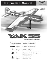
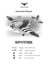
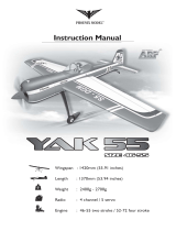
KATANA-61
Wingspan : 1420 mm (56 in)
Length : 1420 mm (56 in)
Weight : 2700g - 3200g
Radio : 6-9 channel/ 6 digital servo
Engine : 61 two stroke
g
Instruction Manual
HOBBIRAN.COM

KIT CONTENTS: We have organized the parts as they come out of the box for better identification
during assembly. We recommend that you regroup the parts in the same manner. This will ensure you
have all of parts required before you begin assembly
MAIN GEAR ASSEMBLY
. (2) Main gear
. (2) 65mm diameter wheels
. (2) Axle set
. (2) Wheel pant
. (4) 4mm x 20mm screw
. (4) Flat washer
TAIL GEAR ASSEMBLY
. (1) Tail gear
. (1) 25mm diameter wheel
. (2) Wheel collar
. (2) Plastic clasp
. (4) 2mm x 16mm screws
ELEVATOR CONTROL SYSTEM
. (2) Control horn
. (2) 3mm x 35mm screw
. (2) Nylon horn
. (2) Metal clevis M3
. (2) 3mm x 12mm screws
. (2) 6mm flat washer
. (2) 3mm nut
. (2) Aluminum ball
. (2) Nylon ball link
. (2) 3mm x 150mm metal pushrod
. (2) 3mm nut
RUDDER CONTROL SYSTEM
. (1) Control horn
. (1) 3mm x 35mm screw
. (1) Nylon horn
. (1) Metal clevis M3
. (1) 3mm x 12mm screws
. (1) 6mm flat washer
. (1) 3mm nut
. (1) Aluminum ball
. (1) Nylon ball link
. (1) 3mm x 70mm metal pushrod
. (1) 3mm nut
AILERON CONTROL SYSTEM
. (2) Control horn
. (2) 3mm x 50mm screw
. (2) Nylon horn
. (2) Metal clevis M3
. (2) 3mm x 12mm screws
. (2) 6mm flat washer
. (2) 3mm nut
. (2) Aluminum ball
. (2) Nylon ball link
. (2) 3mm x 75mm metal pushrod
. (2) 3mm nut
ENGINE MOUNT SYSTEM
. (2) Engine mount
. (4) 4mm x 25mm screw
. (8) 4mm washer C
. (4) 8mm washer
. (4) 4mm x 30mm screw
. (8) 4mm nut
. (1) Metal rod 500mm
. (1) Nylon housing 350mm
. (1) Metal connector
. (1) Fuel tank
. (1) Stopper
. (1) Metal clunk
MISCELLANEOUS ITEMS
. (1) Dihedral
. (4) Wing screw
. (2) Canopy screw
. (4) 2,6mm x 10mm screws
. (1) Spinner
. (1) Cowl
. (1) Plywood plate
. (1) Decal sheet
. (1) Manual book
Instruction Manual KATANA 61
1

2
1 2
3 4
5 6
7 8
Remove the covering. Install and secure the aileron servo.
Mark the holes from the control horn onto the bottom of
the aileron and INLINE with the servo arm.
Drill a hole for control horn.
Secure the control horn. Secure the horn.
The aileron metal pushrod. Install the clevis to the end of the pushrod.
Instruction Manual KATANA 61
1
1Installing the aileron servo:
75mm
22mm 22mm

3
910
11 12
13 14
15 16
Install the nylon control to the end of the pushrod. Adjust the length of the pushrod.
Attach the metal clevis to the nylon control horn. Attach the nylon control to the servo arm and secure it.
Make the center line onto the stabilizer. Remove the covering.
Remove the covering. Make a slot for the rudder hinge.
Instruction Manual KATANA 61
1
2Installing the horizontal and the vertical:
Center line

4
17
18 19
20 21
22 23
Insert the horizontal into the fuselage. Check the horizontal and the wing.
Mark the shape of the fuselage onto the top of the horizontal. And mark the shape of the fuselage onto the bottom of the
horizontal.
Remove the covering. Remove the covering.
Glue the horizontal to the fuselage using the epoxy glue. Glue the horizontal to the fuselage using the epoxy glue.
Instruction Manual KATANA 61
A=A-1
A=A-1
A-1
A
B
AA1
B1

5
24 25
26 27
28 29
30
Remove the covering. Insert the fin to the fuselage.
Insert the hinge into the slot. Mark the shape of the fuselage onto the vertical.
Remove the covering. Insert the vertical into the fuselage.
Check the vertical. Glue the vertical using the epoxy glue.
Instruction Manual KATANA 61
a1
a1 = a2
a2

6
31 32
33 34
35 36
37 38
Remove the covering. Secure the elevator servo.
Install the control horn. Install the nylon horn.
The elevator metal pushrod. Install the metal clevis to the end of the pushrod.
Install the nylon control to the end of the pushrod. Attach the clevis to the nylon control horn.
Instruction Manual KATANA 61
1
3Installing the servo of the elevator:
150mm
22mm 22mm

7
39 40
41 42
43
44 45
Adjust the length of the pushrod. Install the nylon control to the servo arm and secure it.
The second elevator metal pushrod. Make the same way of the second elevator pushrod.
Completed the elevator pushrod.
Remove the covering. Secure the rudder servo.
Instruction Manual KATANA 61
150mm
22mm 22mm
1
4Installing the rudder servo:

8
46 47
48 49
50 51
52 53
Install the control horn. Secure the control horn.
Install the nylon horn. The rudder metal pushrod.
Install the metal clevis to the end of the pushrod. Install the nylon control to the end of the pushrod.
Attach the clevis to the nylon control horn. Adjust the length of the pushrod.
Instruction Manual KATANA 61
70mm
22mm 22mm

9
54
55 56
57 58
59 60
Install the nylon control to the servo arm and secure it.
The tail gear set. Install the wheel.
Install the nylon keeper. Secure the tail gear.
Secure the nylon keeper. Remove the covering.
Instruction Manual KATANA 61
1
5Installing the landing gear:

10
61 62
63
64 65
66 67
The main gear set. Install the wheel pant.
Secure the main gear.
Install the engine mount to the fuselage. Prepare the stopper as picture above.
Install the stopper to the tank. Insert the throttle rod into the fuselage.
Instruction Manual KATANA 61
1
6Installing the fuel tank and the engine:
HOBBIRAN.COM

11
68 69
70 71
72
73 74
Insert the rod to the engine. Install the engine.
Install the throttle servo. Insert the rod into the connector.
Cut away the throttle rod.
Install the switch. And receiver, battery.
Instruction Manual KATANA 61
1
7Installing the switch, battery and receiver:

12
75 76
77 78
79 80
Make the hole for the engine, the muffler. Secure the cowl.
Install the spinner. Remove the covering.
Glue the wing fillets by C.A glue. Secure the canopy to the fuselage.
Instruction Manual KATANA 61
1
8Finishing the model:
Screw

BALANCING
1. It is critical that your airplane be balanced correctly.
Improper balance will cause your plane to lose
control and crash.
THE CENTER OF GRAVITY IS LOCATED 115mm
BACK FROM THE LEADING EDGE OF THE WING,
AT THE FUSELAGE.
2. Mount the wing to the fuselage. Using a couple of
pieces of masking tape, place them on the top side of
the wing 115mm back from the leading edge, at the
fuselage sides.
3. Turn the airplane upside down. Place your fingers on
the masking tape and carefully lift the plane .
4. If the nose of the plane falls, the plane is heavy nose.
To correct this first move the battery pack further
back in the fuselage. If this is not possible or does not
correct it, stick small amounts of lead weight on the
fuselage under the horizontal stabilizer. If the tail of
the plane falls, the plane is tail heavy. To correct this,
move the battery and receiver forward or if this is not
possible, stick weight into the firewall. When balanced
correctly, the airplane should sit level or slightly nose
down when you lift it up with your fingers.
LATERAL BALANCE
After you have balanced a plane on the C.G. You
should laterally balance it. Doing this will help the
airplane track straighter
CONTROL THROWS
1. We highly recommend setting up a plane using the
control throws listed.
2. The control throws should be measured at the widest
point of each control surface.
3. Check to be sure the control surfaces move in the
correct directions.
1. Turn the airplane upside down. Attach one loop of
heavy string to the engine crankshaft and one to the
tail wheel wire. With the wings level, carefully lift
the airplane by the string. This may require two
people to make it easier.
2. If one side of the wing fall, that side is heavier than
the opposite. Add small amounts of lead weight to
the bottom side of the lighter wing half's wing tip.
Follow this procedure until the wing stays level
when you lift the airplane.
115mm
Ailerons : 18 mm up 18 mm down
Elevator : 23 mm up 23 mm down
Rudder : 50 mm right 50 mm left
Elevator Control
Aileron Control
18mm
18mm
Rudder Control
50mm
50mm
23mm
23mm
FLIGHT PREPARATION PRE FLIGHT CHECK
1. Completely charge your transmitter and receiver
batteries before your first day of flying.
2. Check every bolt and every glue joint in your plane
to ensure that everything is tight and well bonded.
3. Double check the balance of the airplane
4. Check the control surface
5. Check the receiver antenna . It should be fully
extended and not coiled up inside the fuselage.
6. Properly balance the propeller.
Instruction Manual KATANA 61
13

8
I/C FLIGHT GUIDELINES
Made in Vietnam
When ready to fly, first extend the
transmitter aerial.
Operate the control sticks on the
transmitter and check that the control
surfaces move freely and in the
CORRECT directions. ALWAYS land the model INTO the
wind, this ensures that the model lands
at the slowest possible speed.
Switch on the transmitter.
Switch off the transmitter.
Check that the transmitter batteries
have adequate power.
Switch off the receiver.
Switch on the receiver. ALWAYS take off into the wind.
Check that the wings are correctly
fitted to the fuselage. If the model does not respond correctly
to the controls, land it as soon as
possible and correct the fault.
Empty the fuel tank after flying, fuel left
in the tank can cause corrosion and
lead to engine problems.
Instruction Manual KATANA 61
/