Page is loading ...

Page 1 of 2
Beghelli U.S.A., 3810 Executive Way, Miramar, Florida, Tel: (954) 442-6600
10/17/23
EPX (COMPACT THERMOPLASTIC LED EXIT SIGN)
INSTALLATION INSTRUCTIONS
IMPORTANT SAFEGUARDS:
When using electrical equipment basic safety precautions should always be followed including the following:
IMPORTANT:
For SA models, battery in this unit may not be fully charged. After electricity is hooked up to unit, let the battery charge
for at least 24 hours. Normal operation of this unit should then take effect.
READ AND FOLLOW ALL SAFETY INSTRUCTIONS:
1. Do not use outdoors.
2. Do not mount near gas or electric heaters.
3. Equipment should be mounted in locations and at heights where it will not be subjected to tampering by unauthorized
personnel.
4. The use of accessory equipment not recommended by the manufacturer may cause an unsafe condition.
5. Do not use this equipment for other than its intended use.
6. Before wiring to power supply, turn o electricity at fuse or circuit breaker.
7. Consult local building code for approved wiring and installation.
8. Installation and servicing should be performed by qualied personnel.
INSTALLATION
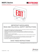
CEILING AND END MOUNT INSTALLATION:
1. Connect input as shown in wiring diagram below and fasten
canopy to the J-box bracket.
2. Snap housing to canopy.
3. Connect the battery (when applicable) to the PC board.
4. Secure faceplate to housing and remove the proper
chevron as required.
SAVE THESE INSTRUCTIONS!
CEILING MOUNT END MOUNT
J-box
bracket
J-box
bracket

Page 2 of 2
Beghelli U.S.A., 3810 Executive Way, Miramar, Florida, Tel: (954) 442-6600
10/17/23
EPX (COMPACT THERMOPLASTIC LED EXIT SIGN)
INSTALLATION INSTRUCTIONS
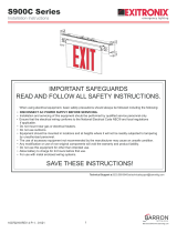
AC ONLY (HT)
WIRING DIAGRAMS:
BATTERY BACKUP (SA)
POWER SUPPLY
PC BOARD
BAT
LED BOARD
WHITE COM
BLACK 120VAC
RED 277VAC
POWER SUPPLY
PC BOARD
LED BOARD
WHITE COM
BLACK 120VAC
RED 277VAC
NOTE: Connect to a single source of power supply so that all lamps are simultaneously illuminated.
NOTE: Properly insulate the unused lead with wire nut or other approved means.
WARNING: Unused wires must be capped using enclosed wire nuts.
OPERATION:
1. Apply AC power to the unit. The LED indicator will be RED.
2. After the battery has been left to charge for 24 hours, test the unit by
pushing the switch. The LED indicator turns OFF, the LED board stays
ON
3. When the switch is released, the LED indicator turns OFF and the LED
indicator turns back to RED.
MAINTENANCE:
Caution: Always turn off AC power to the equipment before servicing.
Servicing should be performed only by a qualified service technician. Use
only MANUFACTURER supplied replacement parts.
BATTERY:
The battery supplied with the Battery Backup (SA) model
requires no maintenance. However, it should be tested periodically (see
TESTING) and replaced when it no longer operates the connected fixtures
for the duration of a 30-second or 90-minute test. The battery supplied in
this equipment has a life expectancy of 5 years when used in a normal
ambient temperature of 72°F.
TESTING:
National Electric Code (NEC) and NFPA life safety code regulations require
that routine tests need to be performed as listed below: Once every month
the unit needs to be tested for duration of 30 seconds. Push in and hold the
test switch to perform this test. Once every 12 months, a full 90 minute (per
UL requirements) test needs to be performed on the unit. Disconnect power
to the unit and leave it in the emergency mode. The LEDs should stay ON
for at least 90 minutes.
/