Page is loading ...

TWIN-N
(2+2 A, 5+5 A, 8+8 A)
SPD-N
(2A, 5A, 8A, 16A)
User’s
manual
Rev. 0.4
October 2010

Parker Hannifin S.p.A. Divisione S.B.C. user’s manual TWIN-N and SPD-N
1
This user manual is for the standard version of the converter.
All information in this user manual, including methods, techniques and concepts described herein,
are proprietary information of Parker Hannifin Divisione S.B.C. – EME Division and of its licensees,
and they shall non be copied or used without express authorization.
Parker Hannifin S.p.A. Divisione S.B.C. is committed to a continuous product upgrade and reserves
the right to modify products and user manuals at any time without prior notice. No part of this user
manual may be howsoever reproduced without previous consent by Parker Hannifin S.p.A. Divisione
S.B.C..
Abbreviations
FBK Feedback.
Pr… Decimal parameter.
b… Binary parameter (bit).
FFW Feedforward, control advance function.
R Read parameter.
W Write parameter.
Keypad-display Keypad
Drive Converter
Cod 1010111700

Parker Hannifin S.p.A. Divisione S.B.C. user’s manual TWIN-N and SPD-N
2
Index:
1 INTRODUCTION ............................................................................................................7
1.1 General information ................................................................................................................ 7
1.2 Product description.................................................................................................................. 7
1.3 Identification............................................................................................................................. 8
1.4 Safety instructions.................................................................................................................. 10
1.4.1 Symbols and signals......................................................................................................... 10
1.4.2 General information ......................................................................................................... 10
1.4.3 Safety instructions for transportation and storage............................................................ 11
1.4.4 Safety instructions for commissioning............................................................................. 11
1.4.5 Safety instructions for operation...................................................................................... 12
1.4.6 Safety instructions for maintenance................................................................................. 13
1.4.7 Compatibility with RCD devices..................................................................................... 13
1.4.8 Applicable standards........................................................................................................ 14
1.4.9 Materials and disposal...................................................................................................... 14
1.4.10 Warranty........................................................................................................................... 15
1.5 Main hardware features ........................................................................................................ 15
1.5.1 Ambient conditions.......................................................................................................... 15
1.5.2 Technical data .................................................................................................................. 16
1.6 Main software features .......................................................................................................... 18
1.7 Expansibility: the Parker-SBC Bridge and its philosophy ................................................ 18
2 MOUNTING ..................................................................................................................20
2.1 How to suppress interference................................................................................................ 20
2.1.1 Grounding ........................................................................................................................ 20
2.1.2 Cable connections and shielding...................................................................................... 21
2.1.3 General suggestions on cable connections....................................................................... 21
2.1.4 Mains and motor side filters............................................................................................. 23
2.2 Signal connectors layout........................................................................................................ 24
2.3 Connections ............................................................................................................................ 26
2.4 Ground connections (PE) ...................................................................................................... 27
2.5 Line connection diagrams ..................................................................................................... 28
2.6 Motor connection diagrams .................................................................................................. 29
2.7 Resolver connection diagrams .............................................................................................. 29
2.8 Signal cables connection ........................................................................................................ 29

Parker Hannifin S.p.A. Divisione S.B.C. user’s manual TWIN-N and SPD-N
3
2.9 Encoder connection................................................................................................................ 30
2.10 Encoder sinusoidal + EnDat connection .............................................................................. 31
2.11 Encoder sinusoidal + Hiperface connection ........................................................................ 32
2.12 Incremental encoder + HALL sensor................................................................................... 33
2.13 SinCos (one sin wave per pole pitch).................................................................................... 34
2.14 Frequecy input/output connection........................................................................................ 35
2.14.1 Connecting the drive to the digital-lock........................................................................... 36
2.15 Serial line connection............................................................................................................. 37
2.16 CAN line connection .............................................................................................................. 38
2.17 External +24V power supply for the control stage ............................................................. 38
2.18 External braking resistance .................................................................................................. 39
3 USING THE KEYBOARD.............................................................................................40
4 POWER SUPPLY MODE .............................................................................................42
4.1 “Low” voltage power supply................................................................................................. 42
4.2 “High” voltage power supply................................................................................................ 43
5 START-UP ...................................................................................................................44
5.1 Setting the default parameters.............................................................................................. 44
5.2 Selection of motor type .......................................................................................................... 44
5.3 Changing motor data............................................................................................................. 45
5.4 Setting feedback ..................................................................................................................... 45
5.4.1 Feedback configuration.................................................................................................... 46
5.4.2 Select supply feedback..................................................................................................... 46
5.5 Feedback from SinCos encoder or SinCsos + Endat encoder............................................ 47
5.6 Feedback from incremental encoder.................................................................................... 48
5.7 Encoder phasing..................................................................................................................... 48
5.7.1 Type 1 phasing................................................................................................................. 48
5.7.2 Type 2 phasing................................................................................................................. 49
5.8 First commissioning ............................................................................................................... 50
5.9 Speed control adjustment...................................................................................................... 51

Parker Hannifin S.p.A. Divisione S.B.C. user’s manual TWIN-N and SPD-N
4
6 PARAMETERS AND PROGRAMMING.......................................................................57
6.1 Main parameters.................................................................................................................... 60
6.2 Binary parameters ................................................................................................................. 65
7 OPERATING MODES ..................................................................................................70
7.1 Position control....................................................................................................................... 71
7.2 Torque control (operating mode 1) ...................................................................................... 74
7.3 Digital Lock + Positioner (operating mode 13) ................................................................... 75
7.3.1 TAB0: profiles in memory............................................................................................... 75
7.4 Electronic cam (operating mode 14)..................................................................................... 79
7.4.1 Positioning ....................................................................................................................... 79
7.4.2 Speed mode...................................................................................................................... 80
7.4.3 Electronic cam.................................................................................................................. 80
7.4.4 OPM 14 Linear engage CAM .......................................................................................... 86
7.5 Electronic cam (op. mod. 11)................................................................................................. 88
7.5.1 Positionator ...................................................................................................................... 89
7.5.2 CAM1 and CAM2............................................................................................................ 89
7.5.2.1 Automatic activation of CAM tables ........................................................................... 93
7.6 Position control through the CANbus (operating mode 15) ............................................ 100
7.7 Basic functions...................................................................................................................... 103
7.7.1 Homing function ............................................................................................................ 103
7.7.2 Speed adjustment ........................................................................................................... 104
7.7.3 Current or torque adjustment (typical)........................................................................... 104
7.7.4 Frequency input/output (Encoder ports) ........................................................................ 104
7.7.5 Value comparators ......................................................................................................... 105
7.7.6 Value capture ................................................................................................................. 105
7.7.7 Output programmable on module .................................................................................. 105
7.7.8 Analogue output programmable..................................................................................... 106
7.7.9 Master reference............................................................................................................. 106
7.7.10 Encoder CAN................................................................................................................. 107
8 PROGRAMMING DIGITAL INPUTS/OUTPUTS ........................................................109
8.1 The pico-PLC ....................................................................................................................... 109
8.2 Programming with MotionWiz........................................................................................... 114
8.3 MotionWiz ............................................................................................................................ 115
9 SERIAL INTERFACE .................................................................................................116
9.1 Communication protocol..................................................................................................... 116

Parker Hannifin S.p.A. Divisione S.B.C. user’s manual TWIN-N and SPD-N
5
10 CAN BUS INTERFACE ..........................................................................................121
10.1 SBC CAN .............................................................................................................................. 121
10.1.1 Description of the fields in real time mode.................................................................... 122
10.1.2 Description of the fields in communication mode......................................................... 129
10.1.3 Description of the fields Extended message set # 2....................................................... 131
10.2 CANopen (C version)........................................................................................................... 133
10.3 CANopen dsp402 (D version).............................................................................................. 141
10.3.1 Dictionary object summary of ds301 in drive................................................................ 142
10.3.2 Dictionary object summary of dsp402 in drive.............................................................. 143
10.3.2.1 Object 6040h: Controlword ................................................................................... 146
10.3.2.2 Object 6041h: Statusword...................................................................................... 148
10.3.2.3 Object 605Bh: Shutdown option code ................................................................... 150
10.3.2.4 Object 605Ch: Disable operation option code ....................................................... 151
10.3.2.5 Object 605Ah: Quick stop option code.................................................................. 152
10.3.2.6 Object 605Eh: Fault reaction option code.............................................................. 152
10.3.2.7 Object 6060h: Modes of operation......................................................................... 153
10.3.2.8 Object 6061h: Modes of operation display............................................................ 153
10.3.3 Functional description.................................................................................................... 154
10.3.3.1 Modes of operation function.................................................................................. 154
10.3.4 Homing mode (operative mode 200) ............................................................................. 155
10.3.5 General information....................................................................................................... 155
10.3.5.1 Input data description............................................................................................. 155
10.3.5.2 Output data description.......................................................................................... 156
10.3.5.3 Internal states ......................................................................................................... 156
10.3.5.3.1 Controlword of homing mode............................................................................ 156
10.3.5.3.2 Statusword of homing mode .............................................................................. 156
10.3.6 Object dictionary entries ................................................................................................ 157
10.3.6.1 Objects defined in this chapter............................................................................... 157
10.3.6.2 Objects defined in other chapters........................................................................... 157
10.3.7 Object description .......................................................................................................... 157
10.3.7.1 Object 607Ch: Home offset.................................................................................... 157
10.3.7.2 Object 6098h: Homing method .............................................................................. 158
10.3.7.3 Object 6099h: Homing speeds ............................................................................... 158
10.3.7.4 Object 609Ah: Homing acceleration...................................................................... 159
10.3.8 Functional description.................................................................................................... 160
10.3.8.1 Homing methods.................................................................................................... 160
10.3.8.1.1 Method 1: Homing on the negative limit switch and index pulse ..................... 160
10.3.8.1.2 Method 2: Homing on the positive limit switch and index pulse ...................... 161
10.3.8.1.3 Methods 3 and 4: Homing on the positive home switch and index pul............. 161
10.3.8.1.4 Methods 5 and 6: Homing on the negative home switch and index pul............ 162
10.3.8.1.5 Methods 7 to 14: Homing on the home switch and index pulse........................ 162
10.3.8.1.6 Methods 15 and 16: Reserved............................................................................ 163
10.3.8.1.7 Methods 17 to 30: Homing without an index pulse........................................... 164
10.3.8.1.8 Methods 31 and 32: Reserved............................................................................ 164
10.3.8.1.9 Methods 33 to 34: Homing on the index pulse .................................................. 164
10.3.8.1.10 Method 35: Homing on the current position.................................................... 164
10.3.9 Profile position mode (operative mode 201).................................................................. 165
10.3.9.1 Internal states ......................................................................................................... 165

Parker Hannifin S.p.A. Divisione S.B.C. user’s manual TWIN-N and SPD-N
6
10.3.9.1.1 Controlword of profile position mode ............................................................... 165
10.3.9.1.2 Statusword of profile position mode.................................................................. 165
10.3.9.2 Object dictionary entries ........................................................................................ 166
10.3.9.2.1 Objects defined in this chapter........................................................................... 166
10.3.9.2.2 Object 607Ah: Target position........................................................................... 166
10.3.9.2.3 Object 6081h: Profile velocity ........................................................................... 167
10.3.9.2.4 Object 6083h: Profile acceleration/deceleration................................................ 167
10.3.9.2.5 Object 6085h: Quick stop deceleration.............................................................. 168
10.3.9.2.6 Object 6086h: Motion profile type..................................................................... 168
10.3.9.3 Functional description............................................................................................ 169
10.3.9.4 Functional description............................................................................................ 170
10.3.10 Interpolated Position Mode (operative mode 202) .................................................... 172
10.3.10.1 Object 60C0h: Interpolation sub mode select........................................................ 173
10.3.10.2 Object 60C1h: Interpolation data record................................................................ 173
10.3.11 Drive parameters........................................................................................................ 176
11 APPENDIX A: MECHANICAL DIMENSIONS ........................................................177
12 APPENDIX B: CONVENTIONS..............................................................................178
13 APPENDIX C: SOFTWARE TIMING ......................................................................178
14 APPENDIX D: DEFAULT PROGRAM FOR PICO-PLC .........................................179
15 APPENDIX E: FLASH INFORMATION ..................................................................180
16 APPENDIX F: ALARMS .........................................................................................181
17 APPENDIX G: OPTION “R” FOR SAFE DISABLE FUNCTION............................183
17.1 Introduction.......................................................................................................................... 183
17.2 Signals description ............................................................................................................... 184
17.3 Drive function blocks........................................................................................................... 186
17.4 Connections .......................................................................................................................... 187
17.5 Operation, sequence and timing ......................................................................................... 187
17.6 Example ................................................................................................................................ 189
17.7 Test and maintenance .......................................................................................................... 189
18 REVISION HISTORY OF THE USER MANUAL.....................................................190

Parker Hannifin S.p.A. Divisione S.B.C. user’s manual TWIN-N and SPD-N
7
1 INTRODUCTION
1.1 General information
This manual describes the installation and commissioning of the frequency converter TWIN-N/SPD-
N for brushless motors.
Read carefully all the sections.
1.2 Product description
The TWIN-N/SPD-N is a digital frequency converter for brushless motors and asynchronous motors
with feedback. The operator interface based on parameters makes it easy to configure the converter.
Configurations of different kinds make suitable it for many applications.
The TWIN-N converter allows controlling two brushless motors with a single converter. This feature
allows saving space into the electric panel in multi-axis configurations. Actually, they are two
different converters that can be used in a totally independent way.
The SPD-N drive is the version to single axis.
The drive features a series of integrated auxiliary functions that allow minimising the control
electronics in the applications, with a considerable cost saving.
It uses widely diffused industrial programming standards and guarantees a high degree of freedom in
selecting inputs and outputs. The drive also offers the possibility to develop additional functions that
are not included in the basic functionality of the converter such as gain correction for loops based on
speed or space, monitoring the used torque for tool life control, etc.
It can be configured through the serial keypad, the serial line or the CAN bus

Parker Hannifin S.p.A. Divisione S.B.C. user’s manual TWIN-N and SPD-N
8
1.3 Identification
The converters of the TWIN-N series are available in 3 models: TWIN 2N, TWIN 5N and TWIN 8N.
The number that follows the TWIN-N abbreviation corresponds to the rated current of the converter
in amperes.
Use the following table to specify the order code:
TWIN 2 N S
X 5 C E Y1 R
8 D H
F
The converters of the SPD-N series are available in 4 models: SPD 2N, SPD 5N, SPD 8N and
SPD16N. The number that follows the SPD -N abbreviation corresponds to the rated current of the
converter in amperes.
Use the following table to specify the order code:
SPD
2 N S
X 5 C E Y1 R
8 D H
16 F
Where :
TWIN / SPD TWIN / SPD servodrive series
X ATEX type drive
2 drive size (nominal current, up to 1 digit: 2, 5, 8, 16)
N New series
S SBC Can protocol (standard)
C CAN Open protocol (DS301)
D CAN Open protocol (DS402)
Resolver
E EnDat/incremental/sinc encoder input (from motor feedback)
H Incremental encoder+hall sensors input (from motor feedback)
F SinCos (one wave per pole pitch)
Y1 Optional board
R Internal safety relay
A label is attached on the right side of the converter that contains all the essential information to
correctly identify the unit:
Serial number
Model
Nominal plate data
It is important to refer to this label before requesting any kind of technical information from Parker
Hannifin S.p.A S.B.C. Division

Parker Hannifin S.p.A. Divisione S.B.C. user’s manual TWIN-N and SPD-N
9
An example of this label is given below.
The performance of converter is guaranteed only with synchronous
motors with permanent magnets
MB and SMB Series that have been manufactured by us.
Model
Power supply
Output voltage
Serial number
Input voltage
In
p
ut fre
q
uenc
y
Out
p
ut fre
q
uenc
y
Input current
Out
p
ut curren
t

Parker Hannifin S.p.A. Divisione S.B.C. user’s manual TWIN-N and SPD-N
10
1.4 Safety instructions
1.4.1 Symbols and signals
Several symbols and signals are used in this safety instruction.
Pay attention to the following meanings :
Extremely severe risk. Disregarding the following advise may involve danger of
life.
Severe risk. Disregarding the following advise may involve serious personal injury.
Medium risk. Disregarding the following advise may involve personal injury
1.4.2 General information
• Only persons who are qualified and trained for the use and operation of the equipment may
work on this equipment or within its proximity. The persons are qualified if they have
sufficient knowledge of the assembly, transportation, installation and operation of the
equipment as well as an understanding of all warnings and precautionary measures noted in
these instructions. The user must also observe local safety regulations.
• Before installing and commissioning the drive, read carefully this documentation and strictly
observe all technical, safety and wiring information, including identifying labels placed on the
drive (ratings). In case of doubt contact the Parker Hannifin service centre.
• Drives are to be intended as components for use in machine or systems. Therefore they can be
used only in machine or systems that are in compliance with the low voltage directive
73/23/CEE (modified by 93/68/CEE) and with the electro-magnetic compatibility directive
89/336/CEE.
• Electronic equipments are generally not “fail-safe” components. Therefore the machine
manufacturers should carry out a risk analysis for the whole machine in order to ensure that
moving parts (motors) cannot bring personal injury in case of failures of electronic devices.

Parker Hannifin S.p.A. Divisione S.B.C. user’s manual TWIN-N and SPD-N
11
1.4.3 Safety instructions for transportation and storage
• The ambient conditions given in the product documentation must be observed for
transportation and storage (temperature, humidity, mechanical stress and aggressive
atmosphere).
• Drives contain components sensitive to electrostatic charges which can be damaged by
inappropriate handling. Therefore during installation / removal of drives, provide the
necessary safety precautions against electrostatic discharges (discharge electrostatic charges
of the human body before touching the drive, always place the drive above conductive plates
and avoid touching it with insulating material like synthetic fibres, polymeric materials etc…)
Risk of injury by incorrect handling !
• Incorrect handing of the equipment may cause severe personal injury. Use appropriate tools
for transportation, lifting, handling and mounting. Wear appropriate clothing for accident-
prevention (safety shoes, safety glasses, safety gloves, etc...).
1.4.4 Safety instructions for commissioning
• The high voltages inside the drive imply risk of electric shock. Make sure that drive and
motor are properly grounded accordingly to national regulations. Furthermore the drive,
before switching it on, must be closed in a protective cabinet in order to avoid direct contact
with accessible live parts.
• Only qualified and trained personnel is allowed to perform installation and commissioning,
using appropriate tools and following the safety precautions given in this instruction. Make
sure that supply voltage has been switched off before installing and wiring.
• Drives are only allowed to be operated on TT, TN grounded industrial mains having
maximum 480V+10% line to line rms voltage, as specified in the user manual. Do not directly
install the drive on ungrounded (IT) or asymmetrically grounded mains. In case of
ungrounded mains, coupling with Dyn transformer with grounded secondary circuit is
necessary. Refer to drive technical data and wiring instruction.
• All the components used in the cabinet in which the drive is installed, (cables, contactors,
inductors and transformers, fuses, etc...), and the connected motor, must be in compliance
with the specification given in the product documentation, in addition to national regulations.
Make sure that the maximum temperature inside the cabinet does not exceed 45°C (113°F). If
necessary, use an appropriate air conditioning.
• The size and temperature rating of wires and cables used for connecting the drive must be in
compliance with the specification given in the instruction manual (see NEC 310-16 for USA).
Use also the specified tightening torque.
• Make sure about the correct drive-motor matching: voltage and current ratings must be
compatible.
• The user is responsible for over-current and short circuit protection of the drive. Read
carefully the specification given in the user manual.

Parker Hannifin S.p.A. Divisione S.B.C. user’s manual TWIN-N and SPD-N
12
1.4.5 Safety instructions for operation
High voltage ! Risk of electric shock ! Danger of life !
• All live parts must be protected against direct contact. The drive must be closed inside a
cabinet before switching it on.
• Working on power live parts (terminals) must be conducted with the drive switched-off.
Dangerous voltages may be present at power terminals even after the supply has been
switched off and the motor stopped. Make sure the equipment cannot switched on
unintentionally. Wait at least 6 minutes before working on live parts after the unit has been
switched-off.
• The drive and the motor must be permanently connected to earth accordingly to the
connection diagram, even for brief measurements or tests.
High leakage current ! Risk of electric shock ! Danger of life !
• Earth leakage current during operation may exceed 3,5 mA AC or 10mA DC.
• Earth connection must be permanent : use copper wire having a minimum size of 10mm2
throughout all the length.
• Before switching the equipment on, make sure that all devices, including the motor, are
permanently connected to earth, even for brief test or measurements, as shown in the wiring
diagrams. Otherwise high voltages may appear on equipment conductive surfaces with danger
of electrical shock.
• Always refer to current local regulations for grounding. For installation within European
Community refer to EN61800-5-1 product standard, section 4.2.5.4.2. For installation in the
USA refer to NEC (National Electric Code) and NEMA (National Electric Manufacturers
Association). The product installation should always comply with the above said standards.
Hot surfaces ! Danger of injury ! Danger of burns !
• Some external surfaces of the equipment and same internal part may reach very high
temperatures. Danger of burn and injury if touching these parts.
• After switching the equipment , wait at least 15 minutes to allow it to cool before touching it.

Parker Hannifin S.p.A. Divisione S.B.C. user’s manual TWIN-N and SPD-N
13
Dangerous movements ! Danger of life !
• Dangerous movements can be caused by faulty control of the connected motor.
Same common example are :
Improper or wrong installation and wiring
Wrong input parameters before or during operation (programming)
Defective components (drive, motor, wires, sensors, etc...)
Incorrect control (software or firmware errors)
• In order to prevent personal injury due to unintended dangerous motor movements, pay the
maximum attention and work on the machine with a qualified and tested safety system :
Isolate the drive power connection.
Mount the emergency stop switch in the immediate reach of the operator. Verify that the
emergency stop works before start-up. Don’t operate the machine if the emergency stop is not
working.
Install properly fences, guards, coverings and light barriers in order to prevent people from
accidentally entering the machine’s range of motion.
Secure vertical axes against falling or dropping after switching off the motor power
Make sure that the drives are brought to a safe standstill before accessing or entering the
danger zone.
1.4.6 Safety instructions for maintenance
• It is extremely dangerous to remove covers or part of the external enclosure from the
equipment. Risk of personal injury. The warranty immediately decay.
• In case of malfunction consult the alarm list described in the user manual or address Parker
Hannifin. The drives are not field repairable.
1.4.7 Compatibility with RCD devices
The use of RCD (Residual Current Devices) is strongly not recommended.
If the use of RCD is mandatory, use type B only (for DC and AC prospective earth current). Set the
trip level at 300mA (fire protection level) or more.
Setting the trip level at 30mA (protection level against direct contact) is possible only using time-
delayed RCD and low leakage current EMC filters, but in any case the drives are not guaranteed to
operate with 30mA trip level.

Parker Hannifin S.p.A. Divisione S.B.C. user’s manual TWIN-N and SPD-N
14
1.4.8 Applicable standards
Safety
2006/95/EC Low voltage directive
EN61800-5-1 Adjustable speed electrical power drive systems - Part 5-1: Safety
requirements- Electrical, thermal and energy
UL508C (USA) Power Conversion Equipment
CSA22.2 Nr. 14-05 (Canada) Power Conversion Equipment
The drive is CE marked in accordance with the Low Voltage Directive when installed and operated
with reference to the product manual.
The drive is considered as a component in machinery. The complete machinery or installation may
only be put into service when in accordance with the safety considerations of the Machinery
Directive 2006/42/EC.
Electromagnetic Compatibility (Immunity/Emission)
2004/108/EC EMC directive
EN 61800-3 Adjustable speed electrical power drive systems - Part 3: EMC
requirements and specific test methods
The drives are intended as components to be used in a second environment (industrial environment)
and category C3, together with specific EMC filters and installed accordingly to the
recommendations given in the user manual. When used in the first environment (residential /
commercial environment), drives may produce radio-frequency interference dangerous for other
equipment: additional filtering measures must be implemented by the user.
1.4.9 Materials and disposal
- zinc coated steel sheet, thickness 1mm and 2mm
- extruded aluminium AlSi
- ABS thickness 2mm minimum (keypad)
- adhesive polycarbonate (front label)
Electrolytic capacitor contain electrolyte and printed circuit boards contain lead, both of which are
classified as hazardous waste and must be removed and handled according to local regulations.
The S.B.C. division of the Parker Hannifin Company, together with local distributors
and in accordance with EU standard 2002/96/EC, undertakes to withdraw and
dispose of its products, fully respecting environmental considerations.

Parker Hannifin S.p.A. Divisione S.B.C. user’s manual TWIN-N and SPD-N
15
1.4.10 Warranty
The warranty duration if 1 (one) year. The converter must not be opened, accessed or modified in any
of its part. Any attempt to do so would cause the 1-year warranty to be cancelled with immediate
effect.. Parker Hannifin declines any responsibility for damages that may be caused by inappropriate
use of the converter.
1.5 Main hardware features
1.5.1 Ambient conditions
operation 0 … 45 °C
32 …113 °F
storage
(1K4 class)
-20 … 55 °C
-4 …131 °F
temperature
transportation
(2K3 class)
-25 … 70 °C
-13…158 °F
relative < 85% without ice and condensation
humidity
(3K3 class) absolute < 25 g/m3
altitude (*) ≤ 1000 m slm
≤ 3281 feet asl
Protection degree IP20 (only in close electric cabinet)
UL open type equipment
Pollution degree 2 or lower
(no conductive dust allowed)
(*) For higher installation altitude, derate the output current by 1.5% each 100m up to 2000m
maximum

Parker Hannifin S.p.A. Divisione S.B.C. user’s manual TWIN-N and SPD-N
16
1.5.2 Technical data
Model
TWIN2N TWIN5N TWIN8N -
Item Unit
SPD2N SPD5N SPD8N SPD16N
Power stage
Mains frequency Hz 50 - 60 ± 5%
3-phase voltage range V~ 200-10% … 480+10%
1-phase voltage range V~ 200-10% … 277+10%
DC voltage range V= 282-10% … 678+10%
Rated output current (*) A rms 2 5 8 16
Peak output current (2 sec) (*) A rms 4 10 16 32
(24@8kHz)
Shaft power (*) kW 1,0 2,6 4,2 7,5
Continuous service installed load (*) kVA 1,4 3,5 5,6 11,2
Control electronics dissipation (*) W 25 60 88 180
Internal fan capacity m3/h 135
Switching frequency kHz 8 4
Output frequency Hz 0 ÷ 450
intermediate DC circuit and dynamic braking
Continuous internal braking power W 120
Peak internal braking power kW 16,2
Braking resistor internal / external Ω 40
Max peak braking current A 20
Max rms braking current (internal resistance) A 0,15
Max duty cycle (internal resistance) % 0,75
Internal DC capacitors µF 470 ±20% 680 ±20%
Braking threshold Vdc 805 - 780
Overvoltage level Vdc 870
Undervoltage level Vdc 70% * √2 *Vsupply
Control stage
Supply voltage V = 24 (-0% … +10%)
Max ripple V pk-pk Do not go over the range
Current rating of the external power supply A 2
Control electronics dissipation W 25
EMC Filter - internal
Hardware characteristics
TWIN-N
SPD-N
TWIN-NE
SPD-NE
Feedback
-
Resolver Encoder
Auxiliary Encoder
Max Frequency
-
kHz
in quadrature encoder (coupled)
400
RS-422 encoder simulation
Max Frequency
step/rev
kHz
4÷65000
160
Serial link - RS-422 / RS-485
Field bus - CAN ISO/DIS11898
(*) the value for TWIN-N is for single axis.

Parker Hannifin S.p.A. Divisione S.B.C. user’s manual TWIN-N and SPD-N
17
Digital inputs
type
number (each single axis)
number (shared by the two axe)
input impedance
Input High voltage range
Input Low voltage range
Type of driving required
Reaction time
-
nr.
nr.
kΩ
V
V
-
μs
Opto coupled
4
2 (IN4,IN5)
2.8
24 ± 10%
0÷5
PNP
< 8
Digital outputs
type
number (each single axis)
Output High voltage range
Output Low voltage range
corrente massima per singola uscita
Overload / Short circuit protection
internal pull-down
-
nr.
V
V
mA
-
kΩ
Opto coupled, PNP open collector
2
> (Vsupply–1)
<1
100
yes
20
Analog reference
Type
number (each single axis)
voltage
CMR
resolution
input impedance
max frequency
-
nr.
V
dB
bit
kΩ
kHz
Differential
1
±10
>80
15 + sign
>18
2
Auxiliary analogue input
Type
number (each single axis)
voltage
CMR
resolution
input impedance
max frequency
-
nr.
V
dB
bit
kΩ
kHz
Differential
1
±10
>80
10
>18
2
Analog output
type
number (each single axis)
voltage
max current
resolution
Overload / Short circuit protection
-
nr.
V
mA
bit
-
single ended (refer to 0VA)
1
±10
1.5
10
yes

Parker Hannifin S.p.A. Divisione S.B.C. user’s manual TWIN-N and SPD-N
18
1.6 Main software features
The following functions have been implemented in the basic software:
Speed controller
Advanced manager of torque limits
Management of speed windows
Torque motor control
Torque control with speed control overlaying
Positioning with trapezoidal Speed profiles
Provides the functions of an electrical shaft with variable ratio and phase correction
Electronic cam
Simulates a stepper motor
It is provided with an internal PLC for programming inputs/outputs
Serial interface RS422-485 integrated: TWIN-N has two independent nodes
Can bus interface: TWIN-N has two independent nodes.
1.7 Expansibility: the Parker-SBC Bridge and its philosophy
Manufacturing companies of machines that use “servo” motor drives frequently have the need of
combining the PLC with the axis control.
The two programmable components are often heterogeneous; the first one sees to the machine logics
management, whereas the second one sees top the motor motion profile management. The skills
required to manage the two products are so different that they require different persons, with a
consequent increase of costs and new problems to manage, that is, the interface between two non-
homogeneous worlds.
Besides having all of the features required by the market of a servo converter, the Parker-S.B.C.
drives for brushless motors are also capable of executing “motion” functions that can be used for a
large number of applications, without having the typical need of programming an axis control. Their
feature is that they can operate as “MOTION ENGINE”, that is, with a component that commands
the motor to execute the desired motion profile, while the MACHINE LOGICS is still managed by
the PLC or by the machine PC.

Parker Hannifin S.p.A. Divisione S.B.C. user’s manual TWIN-N and SPD-N
19
Drive
S.B.C.
Drive
S.B.C.
Drive
S.B.C.
Drive
S.B.C.
Drive
S.B.C.
Drive
S.B.C.
PLC / PC
I / O
Bridge
I / O
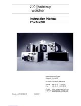
The group of converters used for an application become a single peripheral unit of the PLC/PC using
standard FIELD BUS (Profibus or DeviceNet), and the architecture of the plant control system
becomes of the type shown in the figure.
With the Bridge philosophy, the user or the manufacturer can write motion programs using a standard
PLC, thus avoiding to realise specific application communication protocols.
This philosophy aims at allowing the manufacturer to reach his goals, in terms of time-to-market,
allowing him to focus the efforts on the design activity and avoiding multiple problems connected to
the drive use and interfacing.
/