Cisco ASR 900 Series Aggregation Services Routers Installation guide

Category
Networking
Type
Installation guide
Cisco ASR 914 Aggregation Services Router Hardware Installation
Guide
First Published: 2017-08-16
Last Modified: 2019-07-31
Americas Headquarters
Cisco Systems, Inc.
170 West Tasman Drive
San Jose, CA 95134-1706
USA
http://www.cisco.com
Tel: 408 526-4000
800 553-NETS (6387)
Fax: 408 527-0883
©2017–2020 Cisco Systems, Inc. All rights reserved.
CONTENTS
Cisco ASR 914 Router Overview 1
CHAPTER 1
Cisco ASR 914 Router Features 1
System Specifications 4
GNSS Module 4
GNSS Module RF Input Requirements 5
Power Supply Features 5
Redundancy 6
Dying Gasp 6
Status LEDs 6
Fan Tray 6
Dust Filter (A914-PWR-FAN-F=) 7
RSP Modules 7
Supported RSPs 7
Supported RSP Features 8
RSP Redundancy 9
Network Timing Interfaces 10
RSP Interfaces 10
Interface Modules 11
8-port 10 Gigabit Ethernet Interface Module (8X10GE) (A900-IMA8Z) 11
1-port 100 Gigabit Ethernet Interface Module (1X100GE) (A900-IMA1C) 12
2-Port 100 Gigabit Ethernet Interface Module (2X100GE) (N560-IMA2C) 12
8x1 Gigabit Ethernet SFP+ 1x10 Gigabit Ethernet SFP+ Combination Interface Module
(A900-IMA8S1Z) 14
2-port 40 Gigabit Ethernet QSFP Interface Module (2X40GE) (A900-IMA2F) 15
8/16-Port 1 Gigabit Ethernet (SFP / SFP) + 1-port 10 Gigabit Ethernet (SFP+) / 2-port 1 Gigabit
Ethernet (CSFP) Interface Module (A900-IMA8CS1Z-M) 15
Cisco ASR 914 Aggregation Services Router Hardware Installation Guide
iii
OC-192 Interface Module with 8-port Low Rate CEM Interface Module (10G HO / 10G LO)
(A900-IMA1Z8S-CX) 16
ASR 900 Combo 8-Port SFP GE and 1-Port 10GE With CEM/iMSG, 20G Interface Module
(A900-IMA1Z8S-CXMS) 17
48 X T1/E1 CEM Interface Module (A900-IMA48D-C) 19
48 X T3/E3 CEM Interface Module (A900-IMA48T-C) 19
1-port OC-48/STM-16 or 4-port OC-12/OC-3 / STM-1/STM-4 + 12-Port T1/E1 + 4-Port T3/E3
CEM Interface Module (A900-IMA3G-IMSG) 20
Temperature Sensor 21
Patch Panel 21
Interface Modules 22
Regulatory Compliance 23
Preparing for Installation 25
CHAPTER 2
Safety Guidelines 25
Standard Warning Statements 25
Safety Guidelines for Personal Safety and Equipment Protection 28
Safety Precautions for Module Installation and Removal 28
Safety with Electricity 29
Power Supply Considerations 33
Preventing ESD Damage 34
Site Planning 34
General Precautions 34
Site Planning Checklist 35
Site Selection Guidelines 35
Environmental Requirements 35
Physical Characteristics 36
Assembly Guidelines 36
Air Flow Guidelines 36
Air Flow Guidelines for Enclosed Rack Installation 37
Floor Loading Considerations 37
Site Power Guidelines 37
Electrical Circuit Requirements 39
Site Cabling Guidelines 39
Cisco ASR 914 Aggregation Services Router Hardware Installation Guide
iv
Contents
Asynchronous Terminal Connections 40
Interference Considerations 40
Rack-Mounting Guidelines 40
Precautions for Rack-Mounting 40
Rack Selection Guidelines 41
Equipment Rack Guidelines 41
Installation Checklist 42
Creating a Site Log 43
Receiving the Cisco ASR 914 Router 43
Chassis-Lifting Guidelines 44
Tools and Equipment 45
Unpacking and Verifying the Shipped Contents 46
Installing the Cisco ASR 914 Router 49
CHAPTER 3
Prerequisites 49
Installing the Router in a Rack 49
Installing the Chassis Brackets 49
Installing the Router Chassis in the Rack 50
Installing the Patch Panel on the Rack 52
Installing the Chassis Ground Connection 55
Installing the Fan Tray (A914-F2B-AIR-FAN) 58
Removing the Dust Filter 60
Removing and Replacing the Dust Filter 61
Dust Filter Maintenance 61
Replacing the Fan Tray 62
Installing Fan 3 (A914-PWR-FAN) 62
Removing Fan 3 65
RSP Installation 67
Installing an RSP Module 67
Removing an RSP Module 68
Hot-Swapping an RSP Module 69
Interface Module Installation 69
Installing an Interface Module 70
Removing an Interface Module 71
Cisco ASR 914 Aggregation Services Router Hardware Installation Guide
v
Contents
Hot-Swapping an Interface Module 71
Installing the Power Supply 73
Preventing Power Loss 73
Power Connection Guidelines 73
Guidelines for DC-Powered Systems 74
Installing the DC Power Supply 74
Installing the DC Power Supply Module (A900-PWR550-D) 74
Connecting DC Power Supply Unit (A900-PWR900-D2) 75
Installing DC Power Feeds for Fan Tray 76
Activating the DC Power Supply 78
Removing and Replacing the DC Power Supply 79
Connecting the Cisco ASR 914 Router to the Network 79
Connecting Console Cables 80
Connecting to the Serial Port using Microsoft Windows 80
Connecting to the Console Port using Mac OS X 81
Connecting to the Console Port using Linux 82
Installing the Cisco Microsoft Windows USB Device Driver 83
Uninstalling the Cisco Microsoft Windows USB Driver 84
Connecting to the Auxiliary Port 85
Connecting a Management Ethernet Cable 86
Installing and Removing SFP 86
Connecting a USB Flash Device 87
Removing a USB Flash Device 87
Connecting Timing Cables 87
Connecting Cables to the BITS Interface 87
Connecting Cables to a GNSS Interface 88
Connecting a Cable to the GNSS Antenna Interface 89
Connecting Ethernet Cables 90
Connecting Cables to SFP Modules 91
Connecting T1/E1 cables 91
Installing the Cable Connectors 91
T1/E1 Pinouts 91
Patch Panel cables 91
Patch Panel Cabling for Redundancy 92
Cisco ASR 914 Aggregation Services Router Hardware Installation Guide
vi
Contents
Connecting Cables to the Patch Panel 96
Patch Panel Connectors 97
Installing Patch Panel 97
Install 3G Patch Panel 106
Patch Panel Dimensions 128
Patch Panel Pinout 133
Connecting the Fan Tray Alarm Port 133
Connector and Cable Specifications 134
Cisco ASR 914 Router Initial Configuration 135
CHAPTER 4
Checking Conditions Prior to System Startup 135
Powering Up the Cisco ASR 914 Router 136
Verifying the Front Panel LEDs 136
Verifying the Hardware Configuration 136
Checking Hardware and Software Compatibility 137
Configuring the Cisco ASR 914 Router at Startup 137
Using the Console Interface 137
Configuring Global Parameters 138
Checking the Running Configuration Settings 139
Saving the Running Configuration to NVRAM 139
Safely Powering Off the Cisco ASR 914 Router 140
Troubleshooting 141
CHAPTER 5
Pinouts 141
BITS Port Pinout 141
Wire Wrap Adapter Pinouts 142
GPS Port Pinout 142
Alarm Port Pinout 143
Console/Aux RJ45 RS232 Serial Port Pinout 143
T1/E1 Port Pinouts (RJ-48) 144
AMP64 Pinouts 145
Patch Panel Pinout 150
Management Ethernet Port Pinout 155
USB Console Port Pinout 156
Cisco ASR 914 Aggregation Services Router Hardware Installation Guide
vii
Contents
USB Flash/MEM Port Pinout 157
Fiber-Optic Specifications 157
LED Summary 158
RSP LEDs 158
A900-RSP3C-400-W LED 158
A900-RSP3C-400-W LED Fault Condition 159
Interface Module LEDs 160
OC-192 Interface Module with 8-port Low Rate CEM Interface Module (10G HO / 10G LO)
Interface Module LEDs 161
48 T1/E1 and 48 T3/E3 Interface Module LEDs 162
8-port 10 Gigabit Ethernet Interface Module LEDs 163
1-port 100 Gigabit Ethernet Interface Module LEDs 164
2-port 40 Gigabit Ethernet Interface Module LEDs 164
Power Supply LEDs 165
Fan Tray LEDs 166
Alarm Conditions 167
CLI Commands 167
Site Log and Manufacturers 171
APPENDIX A
Manufacturers 172
Cisco ASR 914 Aggregation Services Router Hardware Installation Guide
viii
Contents
CHAPTER 1
Cisco ASR 914 Router Overview
The Cisco ASR 914 Router is a 14-rack unit router that belongs to the Cisco ASR 900 family of routers. This
router complements Cisco’s offerings for IP RAN solutions for the GSM, UMTS, LTE, and CDMA. Given
its form-factor, interface types and GigabitEthernet density the Cisco ASR 914 Router can also be positioned
as a Carrier Ethernet aggregation platform.
The Cisco ASR 914 Router is a cost optimized, fully redundant, centralized forwarding, extended temperature,
and flexible pre-aggregation router.
•Cisco ASR 914 Router Features, on page 1
•Interface Modules, on page 22
•Regulatory Compliance, on page 23
Cisco ASR 914 Router Features
The key feature of the Cisco ASR 914 Router is to increase per platform and rack-unit interface density,
especially when combining multiple interface types such as Gigabit Ethernet (GE), TDM, 10GE, 40GE and
100GE.
The Cisco ASR 914 Router has the following hardware features:
•A large service scale and high throughput (400G) Route Switch Processors (RSP)—A900-RSP3C-400-W
• One-port 100GE Interface Module (A900-IMA1C)
• Two-port 100 GE Interface Module (N560-IMA2C)
• Two-port 40GE Interface Module (A900-IMA2F)
• Eight-port 10 Gigabit Ethernet Interface Module (8X10GE) (A900-IMA8Z)
• SFP Combo IM—Eight-port Gigabit Ethernet (8X1GE) + One-port 10 Gigabit Ethernet (1X10GE)
(A900-IMA8S1Z)
• OC-192 Interface Module with 8-port Low Rate CEM Interface Module (10G HO / 10G LO)
(A900-IMA1Z8S-CX)
• 48 T1/E1 TDM Interface Module (48XT1/E1) (A900-IMA48D-C)
• 48 T3/E3 TDM Interface Module (48XT3/E3) (A900-IMA48T-C)
• 900 Watt PSUs to power the new RSP modules
Cisco ASR 914 Aggregation Services Router Hardware Installation Guide
1
The Cisco ASR 914 Router includes the following specific components:
• Chassis —14-rack unit in height while still maintaining a shallow depth and front-to-back air flow.
• Fan-tray with removable dust filter.
• New form factor and high performance RSP—This high performance RSP has aggregate switching
capacity of 480 Gbps in oversubscribed mode.
• The backplane and the RSP together have the provision to support higher density 10GE modules like
8x10GE and 100GE modules.
• Integrated air flow baffle allows system to redirect air flow and helps in cooling.
• Flexible I/O configurations through 16 hot pluggable interface modules (single width). For example:
• 16x10G + 2x100G + 80x1G - Oversubscribed mode
• 48x10G - Oversubscribed mode
• 48 T1/E1 TDM Interface Module (48XT1/E1)
• 48 T3/E3 TDM Interface Module (48XT3/E3)
• OC-192 Interface Module with 8-port Low Rate CEM Interface Module (10G HO / 10G LO)
• Metro ENET switching features along with TDM pseudo-wire support.
• Network processor provides flexibility to off-load control plane CPU processing for select OAM and
management packets (for example, CCM, BFD, LBM).
• Flexible ENET processing through table-driven packet processing engines.
• On-line insertion/removal (OIR) of all FRUs except GPS module, while the system is operational.
• Power supply (2+1)—Support for DC power supply. Two PSUs should be powered-on at a time. If all
the three PSUs are powered on, they work in a load-sharing mode.
• Fully-redundant system with redundant combined control plane and data plane (excluding interfaces),
timing support, power supplies, and fans.
• Active and standby support of redundant control plane and data plane, and timing.
• Intra-chassis IOS redundancy (requires both RSPs)
• Stateful-switchover between active and standby RSPs (for protocols supported by IOS).
• In-service software upgrade (ISSU) supported with same RSPs.
• Timing support for receipt and distribution of network frequency and time including SyncE, BITS,
1PPS/10MHz I/O, IEEE 1588-2008, and NTP.
• Support for ENET OAM.
• T1/E1 and T3/E3 line protection compliant with NEBS GR-1089.
• Patch Panel for the Interface Modules.
The following figure illustrates the Cisco ASR 914 Router chassis design.
Cisco ASR 914 Aggregation Services Router Hardware Installation Guide
2
Cisco ASR 914 Router Overview
Cisco ASR 914 Router Features
Figure 1: Cisco ASR 914 Router Chassis Design
Fan Tray Input Terminal Block2Mounting bracket1
Slot 1 for Interface Module4Fan 33
Slot 5 for Interface Module6Slot 3 for Interface Module5
System Enclosure8Slot 7 for Interface Module7
Slot 9 for Interface Module10RSP Slot 19
Slot 13 for Interface Module12Slot 11 for Interface Module11
Ground Lugs14Slot 15 for Interface Module13
Slot 12 for Interface Module16Slot 14 for Interface Module15
Slot 8 for Interface Module18Slot 10 for Interface Module17
Slot 6 for Interface Module20RSP Slot 019
Slot 2 for Interface Module22Slot 4 for Interface Module21
Cable support bracket24Slot 0 for Interface Module23
Fan 1 and Fan 226Redundant power units (three DC power units are shown)25
Cisco ASR 914 Aggregation Services Router Hardware Installation Guide
3
Cisco ASR 914 Router Overview
Cisco ASR 914 Router Features
System Specifications
The following table summarizes the system specifications and environmental requirements for the Cisco ASR
914 Router.
Table 1: Cisco ASR 914 Router System Specifications
24.5 inches x 21.25 inches x 17.1 inches
The additional depth is due to the projection of the handle from
Chassis face.
Note
Dimensions (Height x Width x Depth) with FRUs
Weight
45.359 kg
Chassis with back-plane
5.896 kgFan trays (Top and Bottom)
0.453 kg900W DC PSU
2.8 kgRSP (A900-RSP3C-400-W)
The Cisco ASR 914 Router supports the following temperature ranges at 1800
m operating altitude:
• -5º C to 55º C with front to back air flow
Refer to Datasheets for system configuration.
Note
Operating Temperature
-40º F to 158º F (-40º C to +70º C) storage temperatureNonoperating Temperature
5–95% operating non-condensing relative humidityOperating Humidity
-60 m to 1800 m operating altitude for full operating temperature range; up to
4000 m at up to 40º C.
Operating Altitude
-60 m to 4570 m storage altitudeNonoperating Altitude
1.0 g from 1.0 to 150 HzVibration
30 G half sine 6 ms and 11 msShock
Random: 1.15 g RMS 3 to 200 Hz, 30 minutes/axis
Sine: 10 to 500 Hz at 0.8 G peak / 5 sweep cycles/axis
Nonoperating Vibration
78 dBA at 27ºCOperating Acoustics
GNSS Module
The GNSS module is present on the RSP. It is a pluggable module that allows direct interface with the external
antenna.
Cisco ASR 914 Aggregation Services Router Hardware Installation Guide
4
Cisco ASR 914 Router Overview
System Specifications
Using a single GPS antenna input for both RSPs requires usage of external splitters.
Note
To reduce the risk of fire, use only No. 26 AWG or larger telecommunication line cord. Statement 1023
Warning
The GNSS module is not hot swappable.
Note
GNSS Module RF Input Requirements
• The GNSS module requires an active GPS/GNSS antenna with built-in Low-Noise Amplifier (LNA) for
optimal performance. The antenna LNA amplifies the received satellite signals for two purposes:
• Compensation of losses on the cable
• Lifting the signal amplitude in the suitable range for the receiver frontend
The Amplification required is 22dB gain + cable/connector loss + Splitter signal loss.
The recommended range of LNA gain (LNA gain minus all cable and connector losses) at the connector of
the receiver module is 22dB to 30dB with a minimum of 20dB and a maximum of 35dB.
• GNSS module provides 5V to the active antenna through the same RF input.
• Surge requirement:
GNSS modules have built-in ESD protections on all pins, including the RF-input pin. However, additional
surge protection may be required if rooftop antennas are being connected, to meet the regulations and standards
for lightning protection in the countries where the end-product is installed.
A lightning protection must be mounted at the place where the antenna cable enters the building. The primary
lightning protection must be capable of conducting all potentially dangerous electrical energy to PE (Protective
Earth).
Surge arrestors should support DC-pass and suitable for the GPS frequency range (1.575GHz) with low
attenuation.
• Antenna Sky visibility:
GPS signals can only be received on a direct line of sight between antenna and satellite. The antenna should
see as much as possible from the total sky. For proper timing, minimum of four satellites should be locked.
The antenna terminal should be earthed at the building entrance in accordance with the ANSI/NFPA 70, the
National Electrical Code (NEC), in particular Section 820.93, Grounding of Outer Conductive Shield of a
Coaxial Cable.
Note
Power Supply Features
The Cisco ASR 914 Router supports DC power supplies. The DC power supplies support:
Cisco ASR 914 Aggregation Services Router Hardware Installation Guide
5
Cisco ASR 914 Router Overview
GNSS Module RF Input Requirements
• -40 VDC to -72 VDC
The power supplies are hot-swappable. However, the power supplies are automatically shut down when
removed from the chassis. The power supplies are rated to deliver 900W (~75 A at +12 VDC) to the other
FRUs in the system. The DC power supply has dual input feeds.
The following table shows the DC power supply specifications.
Table 2: DC Power Supply Specifications
A900-PWR900-D2Part numbers
+48 V, -48 VInput power specification
-40.0 VMinimum input voltage
-72 VDCMaximum input voltage
+12 VDCOutput voltage
10 AWG minimum for -48/-60 VDC.
Connector accepts 6 AWG maximum.
Wire gauge for DC input power connections
900 WMaximum power output
For more information about installing the Cisco ASR 914 Router power supplies, see the Installing the Power
Supply .
Redundancy
Three power supplies can be plugged in the Cisco ASR 914 Router chassis that works in the 2+1 redundancy
mode. For the normal operation of the chassis, at least two power supplies should be powered on. When all
the three power supplies are plugged in, they work in a current sharing mode.
Each power supply has dual feed. It is recommended to connect each power feed to a separate input source.
Dying Gasp
The Cisco ASR 914 Router DC power supply does not support the Dying Gasp feature.
Status LEDs
LEDs are also provided on each power supply to indicate the status of the input power and the health of the
power supply. For more information about the LEDs on the Cisco ASR 914 Router, see Troubleshooting
section.
The DC Power Supply Specifications table summarizes the input power specifications for the Cisco ASR 914
Router DC power supply units.
Fan Tray
The Cisco ASR 914 Router fan tray uses:
• A914-PWR-FAN —Three dual rotor fans—for the PSU cooling area
Cisco ASR 914 Aggregation Services Router Hardware Installation Guide
6
Cisco ASR 914 Router Overview
Redundancy
• A914-F2B-AIR-FAN —10 fans (two columns for five fans)—60x60x38mm fans in each fan tray for
cooling RSP and IM area
The fan tray has the following hardware features:
• It provides front-to-back air flow
• It is field replaceable
• It contains status LEDs
For more information about air flow guidelines, see Air Flow Guidelines section. For instructions on how
to install the fan tray, see Installing the Fan Tray (A914-F2B-AIR-FAN) section. For a summary of the LEDs
on the fan tray, see LED Summary section.
Dust Filter (A914-PWR-FAN-F=)
The dust filter on the fan tray is a quadrafoam 45PPI filter which is 80 percent dust resistant. For installing
the fan filter, see Removing and Replacing the Dust Filter section.
RSP Modules
The Cisco ASR 914 Router is designed to use up to two RSP modules to handle the data plane, network timing,
and control plane functionalities for the router. The RSP configuration allows you to use Cisco IOS software
to control chassis management, redundancy, external management, and system status indications on the router.
The following sections describe the Cisco ASR 914 Router RSP:
• Supported RSP Features
• RSP Redundancy
• Network Timing Interfaces
• RSP Interfaces
RSP features include:
• Loading software onto processor-based interface modules
• Redundant RSP management—The RSP manages detection of RSPs, exchange of health and status
information, role negotiation, function for detection, health and status exchange, role negotiation
• Packet processing
• Traffic management, including buffering, queuing, and scheduling, Ethernet MAC functions
• Network clocking functions including phase and time-of-day for BITS, 1 PPS, 10 MHz, and 1588 PTP
clock references
• Storage of software images, system configuration, SysLog
• PTP packet processing including IEEE 1588-2008 for recovering network timing (frequency, phase, and
time) from upstream PTP clocks, for generating PTP frequency and phase references as inputs to the
SETS, and for distributing them to downstream PTP clocks
• External management interfaces (RS232 console, management ENET, USB console, USB storage) and
system status LED indicators
Supported RSPs
The Cisco ASR 914 Router supports the following RSP:
• A900-RSP3C-400-W—Provides 8 GB of SDRAM, 20 Mb of TCAM memory on every ASIC.
Cisco ASR 914 Aggregation Services Router Hardware Installation Guide
7
Cisco ASR 914 Router Overview
Dust Filter (A914-PWR-FAN-F=)
The RSP does not provide external network interfaces for user traffic. All network interfaces are provided
through separate IMs.
Supported RSP Features
The RSP provides the following features on the Cisco router:
• Centralized data plane, timing, and control plane functions for the system
• High-level control of interface modules
• Management functionalities for the router
• Control plane (host) CPU and associated memory in which Cisco IOS XE software and platform control
software runs
• Nonvolatile memory for storage of software images, configurations, and system files
• Enabling and monitoring the health and presence of fan trays, interface modules, and power supplies
• Field replacement and hot-swap capabilities
Swapping of Interface Modules
The following Ethernet interface modules support swapping on the Cisco A900-RSP3C-400-W module:
• SFP Combo IM—8-port Gigabit Ethernet (8X1GE) + 1-port 10 Gigabit Ethernet (1X10GE)
• 2-port 40 Gigabit Ethernet Interface Module (2X40GE)
• 8-port 10 Gigabit Ethernet Interface Module (8X10GE)
• 1-port 100 Gigabit Ethernet Interface Module (1X100GE)
• OC-192 Interface Module with 8-port Low Rate CEM Interface Module (10G HO / 10G LO)
• 48 T1/E1 TDM Interface Module (48XT1/E1)
• 48 T3/E3 TDM Interface Module (48XT3/E3)
Use the hw-modulesubslot default command before performing a swap of the modules to default the interfaces
on the interface module.
There are certain restrictions in using the interface modules on different slots in the chassis. Contact Cisco
Sales/Support for the valid combinations.
Note
Cisco ASR 914 Aggregation Services Router Hardware Installation Guide
8
Cisco ASR 914 Router Overview
Supported RSP Features
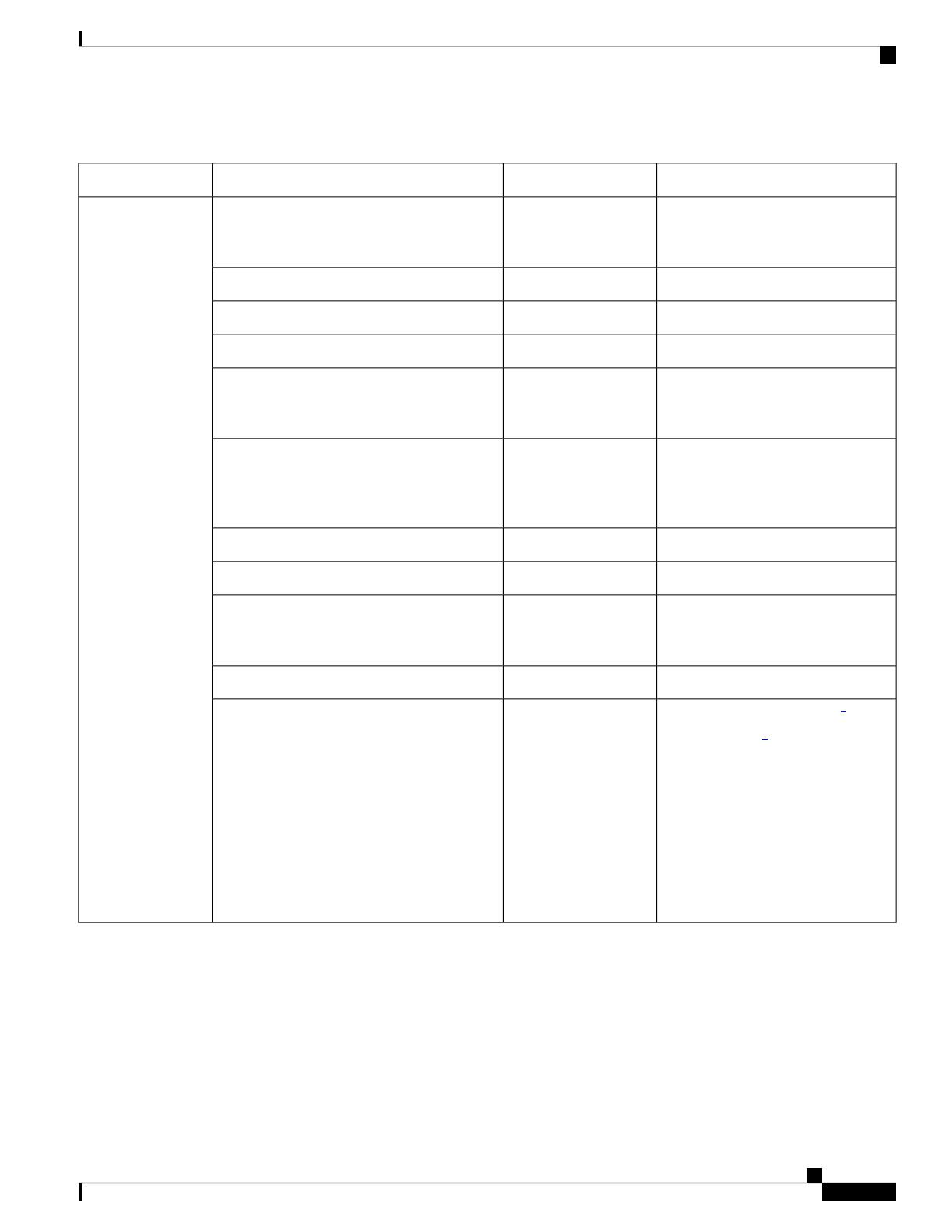
Table 3: Cisco A900-RSP3C-400-W Supported Interface Modules and Part Numbers
SlotPart NumberInterface ModulesRSP Module
2,5,6,9,10,13,14,15A900-IMA8S1ZSFP Combo IM—8-port Gigabit Ethernet
(8X1GE) + 1-port 10 Gigabit Ethernet
(1X10GE)
A900-RSP3C-400-W
7,8A900-IMA1C1x100G Interface module
3,4,7,8,11,12A900-IMA2F2x40G Interface module
3,4,7,8,11,12A900-IMA8Z8x10G Interface module
0,1,2,3,4,5,6,7,8,9,10,11,12,13,14, and
15
A900-IMA8CS1Z-M8/16-port 1 Gigabit Ethernet (SFP/SFP) +
1-port 10 Gigabit Ethernet (SFP+) / 2-port 1
Gigabit Ethernet (CSFP) Interface Module
3,4,7,8,11,12
Other slots are supported
in the 5G mode.
Note
A900-IMA1Z8S-CXOC-192 Interface Module with 8-port Low
Rate CEM Interface Module (10G HO / 10G
LO)
2,3,4,5,6,7,8,9,10,11,12,13,14, and 15A900-IMA48D-C48XT1/E1 Interface module
2,3,4,5,6,7,8,9,10,11,12,13,14, and 15A900-IMA48T-C48XT3/E3 Interface module
2,3,4,5,6,7,8,9,10,13,14, and 15A900-IMA3G-IMSG1-port OC48/ STM-16 or 4-port OC-12/OC-3
/ STM-1/STM-4 + 12-Port T1/E1 + 4-Port
T3/E3 CEM Interface Module
7, 8NCS560-IMA2C2x100G Interface module
0, 1, 2, 5, 6, 9, 10, 13, 14, 151
3, 4, 7, 8, 11, 122
To enable this IM on slot
0 or slot 1, do the
following and reload the
router:
Router# configure t
Router(config)# license
feature
service-offload enable
Note
A900-IMA1Z8S-CXMSCombo 8-Port SFP GE and 1-Port 10GE With
CEM/iMSG 20G Interface Module
1These slots are supported on 10G mode.
2These slots are supported on 20G mode.
RSP Redundancy
The Cisco ASR 914 Router chassis includes two RSP slots to allow for redundant RSPs. When the router uses
redundant RSPs, one RSP operates in the active mode and the other operates in the hot standby mode. Removal
or failure of the active RSP results in an automatic switchover to the standby RSP.
Cisco ASR 914 Aggregation Services Router Hardware Installation Guide
9
Cisco ASR 914 Router Overview
RSP Redundancy
Interface Module Slot support will vary based on Interface Modules used in other slots. For more information,
refer the Configuration Guides for details.
Note
Network Timing Interfaces
The RSP supports the following network timing interfaces:
• BITS input/output port—RJ48 jack
• Wire Wrap Interface Through an Adapter (A900-WWA-RJ48-H)
The BITS adapter comes along with RSP. To order one, use the
A900-WWA-RJ48-H= part number.
Note
• 1 PPS input and output—Mini coax connectors
• 10 MHz input and output—Mini coax connectors
• Time of Day (ToD) or 1 PPS input or output port—Shielded RJ45 jack
Network timing interfaces support redundancy in a redundant RSP configuration. Network timing interfaces
on a redundant RSP remain in operation while the RSP is in hot standby mode.
RSP Interfaces
The following figure summarizes the interfaces on the RSP module.
Figure 2: Interfaces on the RSP Module
InterfaceLabel
1 PPS input timing port1
1 PPS output timing port2
10 MHz input timing port3
10 MHz output timing port4
GNSS RF IN (SMA Threaded Connector)5
USB console port6
USB memory port7
Cisco ASR 914 Aggregation Services Router Hardware Installation Guide
10
Cisco ASR 914 Router Overview
Network Timing Interfaces
InterfaceLabel
Ethernet management port8
BITS timing port9
Interface Modules
The network interfaces are provided through pluggable interface modules.
The following list describes the various IM port density:
• GE SFP ports—Supports 100/1000 modes
• GE C-SFP ports—Supports 100/1000BASE-BX modes
• 100GE CPAK ports using 1x100G IM
• 10GE ports through SFP+
• 2X40 GE interface module—Supports QSFP mode
•T1/E1 ports with integrated inter-office surge protection—Supports TDM channelized, PWE3 processing
• T3/E3 ports - Supports TDM channelized, PWE3 Processing
• OC3/OC12/OC48/OC192 - Supports TDM channelized, PWE3 Processing
The Cisco ASR 914 Router interface modules are a field-replaceable units. In addition to the ports provided
on an RSP, the Cisco ASR 914 Router supports the interface modules.
8-port 10 Gigabit Ethernet Interface Module (8X10GE) (A900-IMA8Z)
Figure 3: 8x10 Gigabit Ethernet Interface Module (A900-IMA8Z)
The high density 8x10 Gigabit Ethernet interface module supports eight 10 Gigabit Ethernet ports using SFP+
transceivers cages on the faceplate.
Cisco ASR 914 Aggregation Services Router Hardware Installation Guide
11
Cisco ASR 914 Router Overview
Interface Modules
It does not support XFP transceivers on the ports.
Note
For more information about installing a 8X10GE module, see the Interface Module Installation section.
1-port 100 Gigabit Ethernet Interface Module (1X100GE) (A900-IMA1C)
Figure 4: 1x100 Gigabit Ethernet Interface Module (A900-IMA1C)
The single port 100 Gigabit Ethernet interface module supports100 Gigabit Ethernet port. The figure above
shows the interface module.
For more information about installing a 1X100GE module, see the Interface Module Installation section.
2-Port 100 Gigabit Ethernet Interface Module (2X100GE) (N560-IMA2C)
The 2-port 100 Gigabit Ethernet Interface Module (N560-IMA2C) design supports only one 100G QSFP28
optics on Port 0. Port 1 is disabled with RSP3. It currently supports only one mode of operation with 100Gbps
of traffic with RSP3.
Cisco ASR 914 Aggregation Services Router Hardware Installation Guide
12
Cisco ASR 914 Router Overview
1-port 100 Gigabit Ethernet Interface Module (1X100GE) (A900-IMA1C)
  • Page 1 1
  • Page 2 2
  • Page 3 3
  • Page 4 4
  • Page 5 5
  • Page 6 6
  • Page 7 7
  • Page 8 8
  • Page 9 9
  • Page 10 10
  • Page 11 11
  • Page 12 12
  • Page 13 13
  • Page 14 14
  • Page 15 15
  • Page 16 16
  • Page 17 17
  • Page 18 18
  • Page 19 19
  • Page 20 20
  • Page 21 21
  • Page 22 22
  • Page 23 23
  • Page 24 24
  • Page 25 25
  • Page 26 26
  • Page 27 27
  • Page 28 28
  • Page 29 29
  • Page 30 30
  • Page 31 31
  • Page 32 32
  • Page 33 33
  • Page 34 34
  • Page 35 35
  • Page 36 36
  • Page 37 37
  • Page 38 38
  • Page 39 39
  • Page 40 40
  • Page 41 41
  • Page 42 42
  • Page 43 43
  • Page 44 44
  • Page 45 45
  • Page 46 46
  • Page 47 47
  • Page 48 48
  • Page 49 49
  • Page 50 50
  • Page 51 51
  • Page 52 52
  • Page 53 53
  • Page 54 54
  • Page 55 55
  • Page 56 56
  • Page 57 57
  • Page 58 58
  • Page 59 59
  • Page 60 60
  • Page 61 61
  • Page 62 62
  • Page 63 63
  • Page 64 64
  • Page 65 65
  • Page 66 66
  • Page 67 67
  • Page 68 68
  • Page 69 69
  • Page 70 70
  • Page 71 71
  • Page 72 72
  • Page 73 73
  • Page 74 74
  • Page 75 75
  • Page 76 76
  • Page 77 77
  • Page 78 78
  • Page 79 79
  • Page 80 80
  • Page 81 81
  • Page 82 82
  • Page 83 83
  • Page 84 84
  • Page 85 85
  • Page 86 86
  • Page 87 87
  • Page 88 88
  • Page 89 89
  • Page 90 90
  • Page 91 91
  • Page 92 92
  • Page 93 93
  • Page 94 94
  • Page 95 95
  • Page 96 96
  • Page 97 97
  • Page 98 98
  • Page 99 99
  • Page 100 100
  • Page 101 101
  • Page 102 102
  • Page 103 103
  • Page 104 104
  • Page 105 105
  • Page 106 106
  • Page 107 107
  • Page 108 108
  • Page 109 109
  • Page 110 110
  • Page 111 111
  • Page 112 112
  • Page 113 113
  • Page 114 114
  • Page 115 115
  • Page 116 116
  • Page 117 117
  • Page 118 118
  • Page 119 119
  • Page 120 120
  • Page 121 121
  • Page 122 122
  • Page 123 123
  • Page 124 124
  • Page 125 125
  • Page 126 126
  • Page 127 127
  • Page 128 128
  • Page 129 129
  • Page 130 130
  • Page 131 131
  • Page 132 132
  • Page 133 133
  • Page 134 134
  • Page 135 135
  • Page 136 136
  • Page 137 137
  • Page 138 138
  • Page 139 139
  • Page 140 140
  • Page 141 141
  • Page 142 142
  • Page 143 143
  • Page 144 144
  • Page 145 145
  • Page 146 146
  • Page 147 147
  • Page 148 148
  • Page 149 149
  • Page 150 150
  • Page 151 151
  • Page 152 152
  • Page 153 153
  • Page 154 154
  • Page 155 155
  • Page 156 156
  • Page 157 157
  • Page 158 158
  • Page 159 159
  • Page 160 160
  • Page 161 161
  • Page 162 162
  • Page 163 163
  • Page 164 164
  • Page 165 165
  • Page 166 166
  • Page 167 167
  • Page 168 168
  • Page 169 169
  • Page 170 170
  • Page 171 171
  • Page 172 172
  • Page 173 173
  • Page 174 174
  • Page 175 175
  • Page 176 176
  • Page 177 177
  • Page 178 178
  • Page 179 179
  • Page 180 180

Cisco ASR 900 Series Aggregation Services Routers Installation guide

Category
Networking
Type
Installation guide

Ask a question and I''ll find the answer in the document

Finding information in a document is now easier with AI