GB
Valid for serial no. 620-xxx-xxxx, 917-xxx-xxxx0459 162 101 GB 20120904
Origo™ M13
Feed 304
Feed 484
Instruction manual
- 2 -
- 3 -
TOCe
Rights reserved to alter specifications without notice.
1 SAFETY 4...........................................................
2 INTRODUCTION 5...................................................
2.1 Equipment 6................................................................
3 TECHNICAL DATA 6.................................................
4 INSTALLATION 7....................................................
4.1 Lifting instructions 7.........................................................
5 OPERATION 8.......................................................
5.1 Connections and control devices 9............................................
5.2 Water connection 9..........................................................
5.3 Starting procedure 9.........................................................
5.4 Function explanations 10......................................................
5.5 Wire feed pressure 11........................................................
5.6 Changing / loading wire Feed 304 12............................................
5.7 Changing / loading wire Feed 484 12............................................
5.8 Changing feed rollers on Feed 304 12...........................................
5.9 Changing feed rollers on Feed 484 13...........................................
6 MAINTENANCE 13....................................................
6.1 Inspection and cleaning 13....................................................
7 ORDERING SPARE PARTS 14.........................................
DIAGRAM 16............................................................
ORDER NUMBER 21.....................................................
WEAR PARTS 22........................................................
ACCESSORIES 26.......................................................
© ESAB AB 2002
- 4 -
bm34d1ea
1 SAFETY
Users of ESAB equipment have the ultimate responsibility for ensuring that anyone who works on or
near the equipment observes all the relevant safety precautions. Safety precautions must meet the
requirements that apply to this type of equipment. The following recommendations should be ob
served in addition to the standard regulations that apply to the workplace.
All work must be carried out by trained personnel well-acquainted with the operation of the equip
ment. Incorrect operation of the equipment may lead to hazardous situations which can result in in
jury to the operator and damage to the equipment.
1. Anyone who uses the equipment must be familiar with:
S its operation
S location of emergency stops
S its function
S relevant safety precautions
S welding and cutting
2. The operator must ensure that:
S no unauthorised person is stationed within the working area of the equipment when it is
started up.
S no-one is unprotected when the arc is struck
3. The workplace must:
S be suitable for the purpose
S be free from drafts
4. Personal safety equipment
S Always wear recommended personal safety equipment, such as safety glasses, flame-proof
clothing, safety gloves.
S Do not wear loose-fitting items, such as scarves, bracelets, rings, etc., which could become
trapped or cause burns.
5. General precautions
S Make sure the return cable is connected securely.
S Work on high voltage equipment may only be carried out by a qualified electrician.
S Appropriate fire extinquishing equipment must be clearly marked and close at hand.
S Lubrication and maintenance must not be carried out on the equipment during operation.
CAUTION
Read and understand the instruction manual before
installing or operating.
CAUTION
Class A equipment is not intended for use in residential locations where
the electrical power is provided by the public low-voltage supply system.
There may be potential difficulties in ensuring electromagnetic
compatibility of class A equipment in those locations, due to conducted
as well as radiated disturbances.
CAUTION
This product is solely intended for arc welding.
GB
© ESAB AB 2002
- 5 -
bm34d1ea
WARNING
Read and understand the instruction manual before installing or operating.
Arc welding and cutting can be injurious to yourself and others. Take precautions when welding and
cutting. Ask for your employer's safety practices which should be based on manufacturers' hazard
data.
ELECTRIC SHOCK - Can kill
S Install and earth the unit in accordance with applicable standards.
S Do not touch live electrical parts or electrodes with bare skin, wet gloves or wet clothing.
S Insulate yourself from earth and the workpiece.
S Ensure your working stance is safe.
FUMES AND GASES - Can be dangerous to health
S Keep your head out of the fumes.
S Use ventilation, extraction at the arc, or both, to take fumes and gases away from your breathing zone
and the general area.
ARC RAYS - Can injure eyes and burn skin.
S Protect your eyes and body. Use the correct welding screen and filter lens and wear protective
clothing.
S Protect bystanders with suitable screens or curtains.
FIRE HAZARD
S Sparks (spatter) can cause fire. Make sure therefore that there are no inflammable materials nearby.
NOISE - Excessive noise can damage hearing
S Protect your ears. Use earmuffs or other hearing protection.
S Warn bystanders of the risk.
MALFUNCTION - Call for expert assistance in the event of malfunction.
PROTECT YOURSELF AND OTHERS!
Dispose of electronic equipment at the recycling facility!
In observance of European Directive 2002/96/EC on Waste Electrical and Electronic
Equipment and its implementation in accordance with national law, electrical and/or
electronic equipment that has reached the end of its life must be disposed of at a
recycling facility.
As the person responsible for the equipment, it is your responsibility to obtain
information on approved collection stations.
For further information contact the nearest ESAB dealer.
ESAB can provide you with all necessary welding protection and accessories.
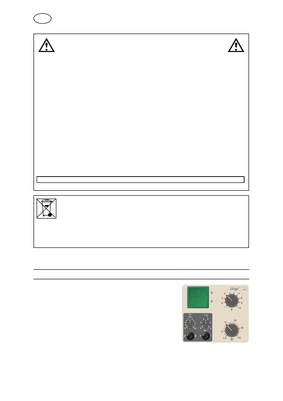
2 INTRODUCTION
The Feed 304and Feed 484 wire feed units with control
panel M13 are intended for MIG/MAG-welding together
with infinitely adjustable welding power sources.
They come in different variants, see on page 21.
The wire feed units are sealed and contain four-wheel
drive wire feed mechanisms as well as control electronics.
They can be used together with wire on ESAB's
MarathonPact, or on wire bobbin (standard Ø 300 mm,
accessory Ø 440 mm).
The wire feed unit can be installed either at the power source, suspended above the
workplace, on a support arm or on the floor with or without wheel set.
GB
© ESAB AB 2002
- 6 -
bm34d1ea
ESAB's accessories for the product can be found on page 26.
2.1 Equipment
The Feed 304 wire feed unit is supplied with:
S Instruction manual
S Stickers with recommended wear parts.
The Feed 484 wire feed unit is supplied with:
S Spacer (4)
S Hex key wrench (4 mm)
S Instruction manual
S Stickers with recommended wear parts.
3 TECHNICAL DATA
Feed 304 Feed 484
Power supply 42 V 50 - 60 Hz 42 V 50 - 60 Hz
Power requirement 336 VA 378 VA
Motor current I
max
8 A 9 A
Settings data
Wire feed speed
Burnback time
Crater filling time
Creep start
2/4 stroke
1.9-25.0 m/min
0-0.5 s
0-5.1 s
OFF or ON
2 stroke or 4 stroke
1.9-25.0 m/min
0-0.5 s
0-5.1 s
OFF or ON
2 stroke or 4 stroke
Gun connection EURO EURO
Max. diameter wire bobbin 300 mm (*440mm) 300 mm (*440mm)
Wire dimension 0.6-1.6 mm 0.6-2.4 mm
Weight
basic version
with sealed bobbin holder
11.5 kg
15 kg
14.5 kg
19 kg
Dimensions (l x w x h)
basic version
with sealed bobbin holder
380 x 275 x 400 mm
690 x 275 x 420 mm
380 x 275 x 400 mm
690 x 275 x 420 mm
Operating temperature -10 to +40° C -10 to +40° C
Shielding gas
max pressure
All types intended for
MIG/MAG welding
5 bar
All types intended for
MIG/MAG welding
5 bar
Coolant
max pressure
50% water / 50% glycol
5 bar
50% water / 50% glycol
5 bar
Permissible load at
60% duty cycle 630 A 630 A
Enclosure class IP23 IP23
* Accessories, see page 26.
GB
© ESAB AB 2002
- 7 -
bm34d1ea
Duty cycle
The duty cycle refers to the time as a percentage of a ten-minute period that you can weld or cut at
a certain load without overloading. The duty cycle is valid for 40° C.
Enclosure class
The IP code indicates the enclosure class, i. e. the degree of protection against penetration by solid
objects or water. Equipment marked IP23 is designed for indoor and outdoor use.
4 INSTALLATION
The installation must be carried out by a professional.
WARNING
When welding in an environment with increased electrical danger, only power
sources intended for this environment may be used. These power sources are
marked with the symbol
4.1 Lifting instructions
Ordering number for the lifting eye can be found on page 26.
Note! If another mounting device is used, this should be insulated from the wire feed
unit.
GB
© ESAB AB 2002
- 8 -
bm34d1ea
5 OPERATION
General safety regulations for handling the equipment can be found on
page 4. Read through before you start using the equipment!
WARNING
Assure that the side panels are closed during operation.
WARNING
To prevent the reel from sliding off the hub: Lock the
reel in place by turning the red knob as shown on the
warning label attached next to the hub.
WARNING
Rotating parts can cause injury, take great care.
WARNING
Risk of crushing when replacing the wire bobbin!
Do not use safety gloves when inserting the welding wire between the feed rollers.
WARNING
There is a risk of tipping if the wire feed unit is fitted with a counterbalance arm.
Secure the equipment, especially if used on an uneven or sloping surface.
NOTE: When moving the equipment use intended handle. Never pull on the gun.
GB
© ESAB AB 2002
- 9 -
bm34d1ea
5.1 Connections and control devices
1 Display 9 Connection for welding gun
2 Knob for setting the voltage 10 Switch for 2-stroke / 4-stroke
3 Knob for setting crater filling time 11 Knob for setting burnback time
4 Switch for creep start OFF / ON 12 Connection for welding current from power
source, (OKC)
5 Knob for setting wire feed speed. 13 Connection for control cable from power
source
6 Connection for remote control unit,
Miggytrac, Railtrac
14 Connection RED for cooling water to
power source (cooling unit)
7 Connection BLUE, with ELP* for cooling
water to the welding gun
15 Connection BLUE for cooling water from
power source (cooling unit)
8 Connection RED for cooling water from
welding gun
16 Connection for shielding gas
NOTE! Display (digital instrument) and cooling water connections only available on certain models.
* ELP = ESAB Logic Pump, see point 5.2.
5.2 Water connection
When connecting a water-cooled welding gun, the power source's main power
supply switch must be in the Off position and the cooling unit switch must be in
position “ELP/0”.
The wire feed unit with water connection is equipped with a detection system ELP
(ESAB Logic Pump) which checks that the water hoses are connected. When
connecting a water-cooled welding gun, the water pump starts.
Detection only works with power sources that are equipped with ELP.
5.3 Starting procedure
When the wire feed starts, the power source generates welding voltage.
If there is no welding current flow within three seconds, the power source switches
the welding voltage off. The wire feed continues until the welding gun's switch is
switched off.
GB
© ESAB AB 2002
- 10 -
bm34d1ea
5.4 Function explanations
Burnback time
Burnback time is a delay between the time when the wire starts to brake until the
time when the power source switches off the welding voltage. Too short burnback
time results in a long wire stickout after completion of welding, with a risk of the wire
being caught in the solidifying weld pool. Too long a burnback time results in a
shorter stickout, with increased risk of the arc striking back to the contact tip.
Crater filling
Crater filling helps to avoid pores, thermal cracking and crater formation in the weld
when welding stops.
Figure 1 shows an interruption in the
welding, and a crack or crater opens up
readily in the solidified central part due
to shrinkage during the solidifying pro
cess.
Fig. 1.After welding without crater filling
Figure 2 shows that the arc continues to
give off a certain amount of heat while
the weld pool is solidifying. This chang
es the solidification process so that the
last solidified part of the weld pool ends
up at the top, and in this way it is possib
le to avoid the occurrence of a crater.
Fig. 2.After welding with crater filling
2 stroke
With 2 stroke, wire feed starts when the trigger switch is pressed in and ends when
it is released.
4 stroke
With 4 stroke, the gas flow starts when the trigger switch is pressed in and the wire
feed starts when it is released. The welding process continues until the switch is
pressed in again, the wire feed stops and when the switch is released the gas stops
flowing.
Creep start
Creep start means that the wire is fed at low speed until it comes into electrical
contact with the workpiece and then the speed increases to the set speed.
GB
© ESAB AB 2002
- 11 -
bm34d1ea
Wire feed speed
This sets the required feed speed of the filler wire in m/minute.
5.5 Wire feed pressure
Start by making sure that the wire moves smoothly through the wire guide. Then
set the pressure of the wire feeder's pressure rollers. It is important that the
pressure is not too great.
Fig 1 Fig 2
To check that the feed pressure is set correctly, you can feed out the wire against
an insulated object, e.g. a piece of wood.
When you hold the gun approx. 5 mm from the piece of wood (fig. 1) the feed
rollers should slip.
If you hold the gun approx. 50 mm from the piece of wood, the wire should be
fed out and bend (fig. 2).
GB
© ESAB AB 2002
- 12 -
bm34d1ea
5.6 Changing / loading wire Feed 304
S Open the side panel.
S Disconnect the pressure sensor by folding it backwards, the pressure rollers
slide up.
S Straighten out the new wire 10-20 cm. File away burrs and sharp edges from the
end of the wire before inserting it into the wire feed unit.
S Make sure that the wire goes properly into the feed roller's track and into the
outlet nozzle or wire guide.
S Secure the pressure sensor.
S Close the side panel.
5.7 Changing / loading wire Feed 484
S Open the side panel.
S Press down and pull the pressure device towards you and up.
S Pull out the bogie.
S Straighten out the new wire 10-20 cm. File away burrs and sharp edges from the
end of the wire before inserting it into the wire feed unit.
S Make sure that the wire goes properly into the feed roller's track and into the
outlet nozzle or wire guide.
S Reinstall the bogie.
S Close the side panel.
5.8 Changing feed rollers on Feed 304
S Open the side panel.
S Disconnect the pressure sensor (1) by folding it
backwards.
S Disconnect the pressure rollers (2) by turning the
axle (3) 1/4 turn clockwise and pulling out the axle.
The pressure rollers disconnect.
S Disconnect the feed rollers (4) by unscrewing the nuts
(5) and pulling out the rollers.
During installation, repeat the above in the reverse order.
Choice of tracks in the feed rollers
Turn the feed roller with the dimensioning mark for the required
track towards you.
GB
© ESAB AB 2002
- 13 -
bm34d1ea
5.9 Changing feed rollers on Feed 484
S Open the side panel.
S Press down and pull the pressure device (1) towards
you and up.
S Pull out the bogie (2).
S Undo the socket head cap screws (3) on the holder
for the intermediate nozzle and remove the
holder.
S Undo the screw for the outlet nozzle (4) and
push back the nozzle.
S Completely undo the socket head cap screw
(5) in the centre.
S Undo the two outer socket head cap screws (6) 1/2 a
turn.
S Pull out the feed rollers (7).
During installation, repeat the above in the reverse order.
Choice of tracks in the feed rollers
Place no, one or two driving washers
between the outer washer and the feed
roller. Note! When replacing the
pressure rollers (8), the entire bogie is
replaced.
6 MAINTENANCE
Regular maintenance is important for safe, reliable operation.
CAUTION
All guarantee undertakings from the supplier cease to apply if the customer attempts any
work to rectify any faults in the product during the guarantee period.
6.1 Inspection and cleaning
Wire feed unit
Check regularly that the wire feed unit is not clogged with dirt.
S Cleaning and replacement of the wire feed unit mechanism's worn parts should
take place at regular intervals in order to achieve trouble-free wire feed. Note
that if pre-tensioning is set too hard, this can result in abnormal wear on the
pressure roller, feed roller and wire guide.
GB
© ESAB AB 2002
- 14 -
bm34d1ea
The brake hub
The hub is adjusted when delivered, if
readjustment is required, follow the instructions
below. Adjust the brake hub so that wire is slightly
slack when wire feed stops.
S Adjusting the braking torque:
S Turn the red handle to the locked position.
S Insert a screwdriver into the springs in the hub.
Turn the springs clockwise to reduce the braking torque
Turn the springs counter-clockwise to increase the braking torque. NB: Turn
both springs the same amount.
Welding gun
S The welding gun's wear parts should be cleaned and replaced at regular
intervals in order to achieve trouble-free wire feed. Blow the wire guide clean
regularly and clean the contact tip.
7 ORDERING SPARE PARTS
Feed 304, Feed 484 is designed and tested in accordance with the international and
European standards IEC-/ EN 60974-5 and IEC- / EN 60974-10. It is the obligation of
the service unit which has carried out the service or repair work to make sure that the
product still conforms to the said standard.
Spare parts may be ordered through your nearest ESAB dealer, see the last page of
this publication.
GB
- 15 -
p
© ESAB AB 2002
Diagram
- 16 -
bm34e11a
Feed 304 M13 valid for serial no 620-xxx-xxxx
Feed 484 M13 valid for serial no
620-xxx-xxxx and 917-xxx-xxxx
© ESAB AB 2002
- 17 -
bm34e11a
© ESAB AB 2002
- 18 -
bm34e11a
Feed 304 M13 valid for serial no 917-xxx-xxxx
© ESAB AB 2002
- 19 -
bm34e11a
- 20 -
p
  • Page 1 1
  • Page 2 2
  • Page 3 3
  • Page 4 4
  • Page 5 5
  • Page 6 6
  • Page 7 7
  • Page 8 8
  • Page 9 9
  • Page 10 10
  • Page 11 11
  • Page 12 12
  • Page 13 13
  • Page 14 14
  • Page 15 15
  • Page 16 16
  • Page 17 17
  • Page 18 18
  • Page 19 19
  • Page 20 20
  • Page 21 21
  • Page 22 22
  • Page 23 23
  • Page 24 24
  • Page 25 25
  • Page 26 26
  • Page 27 27
  • Page 28 28
  • Page 29 29
  • Page 30 30
  • Page 31 31
  • Page 32 32

Ask a question and I''ll find the answer in the document

Finding information in a document is now easier with AI