Page is loading ...

KTFRDMCD1020EVMUG
FRDMCD1020EVM Evaluation Board
Rev. 1 — 31 January 2018 User guide
1 FRDMCD1020EVM Evaluation Board
Figure 1. FRDMCD1020EVM

NXP Semiconductors
KTFRDMCD1020EVMUG
FRDMCD1020EVM Evaluation Board
KTFRDMCD1020EVMUG All information provided in this document is subject to legal disclaimers. © NXP B.V. 2018. All rights reserved.
User guide Rev. 1 — 31 January 2018
2 / 26
2 Important notice
NXP provides the enclosed product(s) under the following conditions:
This evaluation kit is intended for use of ENGINEERING DEVELOPMENT OR
EVALUATION PURPOSES ONLY. It is provided as a sample IC pre-soldered to a
printed circuit board to make it easier to access inputs, outputs, and supply terminals.
This evaluation board may be used with any development system or other source of
I/O signals by simply connecting it to the host MCU or computer board via off-the-
shelf cables. This evaluation board is not a Reference Design and is not intended to
represent a final design recommendation for any particular application. Final device in
an application will be heavily dependent on proper printed circuit board layout and heat
sinking design as well as attention to supply filtering, transient suppression, and I/O
signal quality.
The goods provided may not be complete in terms of required design, marketing, and
or manufacturing related protective considerations, including product safety measures
typically found in the end product incorporating the goods. Due to the open construction
of the product, it is the user's responsibility to take any and all appropriate precautions
with regard to electrostatic discharge. In order to minimize risks associated with the
customers applications, adequate design and operating safeguards must be provided
by the customer to minimize inherent or procedural hazards. For any safety concerns,
contact NXP sales and technical support services.
Should this evaluation kit not meet the specifications indicated in the kit, it may be
returned within 30 days from the date of delivery and will be replaced by a new kit.
NXP reserves the right to make changes without further notice to any products herein.
NXP makes no warranty, representation or guarantee regarding the suitability of its
products for any particular purpose, nor does NXP assume any liability arising out of the
application or use of any product or circuit, and specifically disclaims any and all liability,
including without limitation consequential or incidental damages. Typical parameters
can and do vary in different applications and actual performance may vary over time. All
operating parameters, including Typical, must be validated for each customer application
by customer’s technical experts.
NXP does not convey any license under its patent rights nor the rights of others. NXP
products are not designed, intended, or authorized for use as components in systems
intended for surgical implant into the body, or other applications intended to support or
sustain life, or for any other application in which the failure of the NXP product could
create a situation where personal injury or death may occur.
Should the Buyer purchase or use NXP products for any such unintended or
unauthorized application, the Buyer shall indemnify and hold NXP and its officers,
employees, subsidiaries, affiliates, and distributors harmless against all claims, costs,
damages, and expenses, and reasonable attorney fees arising out of, directly or
indirectly, any claim of personal injury or death associated with such unintended or
unauthorized use, even if such claim alleges NXP was negligent regarding the design or
manufacture of the part.
NXP and the NXP logo are trademarks of NXP B.V. All other product or service names
are the property of their respective owners. © NXP B.V. 2018.

NXP Semiconductors
KTFRDMCD1020EVMUG
FRDMCD1020EVM Evaluation Board
KTFRDMCD1020EVMUG All information provided in this document is subject to legal disclaimers. © NXP B.V. 2018. All rights reserved.
User guide Rev. 1 — 31 January 2018
3 / 26
3 Getting Started
The NXP analog product development boards provide an easy-to-use platform for
evaluating NXP products. The boards support a range of analog, mixed-signal and
power solutions. They incorporate monolithic integrated circuits and system-in-package
devices that use proven high-volume technology. NXP products offer longer battery life, a
smaller form factor, reduced component counts, lower cost and improved performance in
powering state-of-the-art systems.
The tool summary page for FRDMCD1020EVM switch detection interface evaluation kit
is located at www.nxp.com/FRDMCD1020EVM. The link provides access to overview
information, documentation, software and tools for the FRDMCD1020EVM. The overview
tab provides a device overview, list of device features, a description of the kit contents,
links to any applicable supported devices and a Get Started section. The Get Started
section provides links to everything needed to start using the device and contains the
most relevant, current information applicable to the FRDMCD1020EVM evaluation kit.
1. Go to www.nxp.com/FRDMCD1020EVM
2. On the Overview tab, locate the Jump To navigation feature on the left side of the
window.
3. Select the Get Started link or scroll in the main window of the Overview tab until the
Get Started section is visible.
4. Review each entry in the Get Started section.
5. Download an entry by clicking on the linked title.
After reviewing the Overview tab, visit the other related tabs for additional information:
• Documentation: Download current documentation
• Software & Tools: Download current hardware and software tools
• Buy/Parametrics: Purchase the product and view the product parametrics.
After downloading files, review each file, including the user guide which includes setup
instructions. If applicable, the bill of materials (BOM) and supporting schematics are also
available for download in the Get Started section of the Overview tab.
3.1 Kit contents/packing list
The FRDMCD1020EVM development kit contents include:
• Assembled and tested FRDMCD1020EVM customer evaluation board/module and
preprogrammed FRDM-KL25Z SPI Communication Board in an anti-static bag
• USB Male (standard) to USB Male (mini) cable
• Quick Start Guide

NXP Semiconductors
KTFRDMCD1020EVMUG
FRDMCD1020EVM Evaluation Board
KTFRDMCD1020EVMUG All information provided in this document is subject to legal disclaimers. © NXP B.V. 2018. All rights reserved.
User guide Rev. 1 — 31 January 2018
4 / 26
3.2 Required hardware and software
To use this kit, you need:
• Power supply 12 V with at least 1.0 A current capability
• KIT-SW33-EVB (optional) or any other type of ON-OFF switch to ground or switch to
battery loads
• SPI Generator (SPIGen) software, version 7.1.8 or later, a Graphical User Interface
(GUI)
3.3 System requirements
The kit requires the following to function properly with the software:
• Windows 10, Windows 8 or Window 7 compatible PC with an available USB port

NXP Semiconductors
KTFRDMCD1020EVMUG
FRDMCD1020EVM Evaluation Board
KTFRDMCD1020EVMUG All information provided in this document is subject to legal disclaimers. © NXP B.V. 2018. All rights reserved.
User guide Rev. 1 — 31 January 2018
5 / 26
4 Getting to know the hardware
4.1 Board overview
The FRDMCD1020EVM Evaluation Board (EVB) features the CD1020, a 22-channel
switch detection interface with programmable wetting current. The kit is designed to
detect the opening and closing of up to 22 switch contacts. The switch status, either open
or closed, is transferred to the microprocessor unit (MCU) through a serial peripheral
interface (SPI). The device also features a 22-to-1 analog multiplexer for reading the
analog voltage at the inputs.
The analog input signal is buffered and provided on the AMUX output pin to be read by
an external MCU. The CD1020 device has two modes of operation, Normal and Sleep.
Normal mode allows programming of the device and supplies switch contacts with pull-
up or pull-down current as it monitors switch change-of-state, while the sleep mode
provides switch status detection with maximum power saving. The FRDMCD1020EVM
can be controlled through a USB/SPI communication board (FRDM-KL25Z) connected
to the PC’s USB port. The NXP SPIGen (version 7.0 and above) program provides the
user interface to the CD1020 SPI port and allows the user to program the configuration
registers, send commands to the IC and receive status from the IC.
4.2 Board features
The board features include:
• CD1020 device with 22 channel switch detection and status report capability
• Single row interface connectors for the NXP FRDM-KL25Z pre-programmed
communication board
• Status LEDs to report the status of the CD1020 Interrupt (INT) and Wake-up lines
• Single load connector with 36 pin, 100 MIL pin spacing for easy interface with external
switch loads
• Direct connection to battery power with optional 3.3 V / 5.0 V LDO for VDDQ rail supply
4.3 Board description
Figure 2 identifies important components on the FRDMCD1020EVM board and Table 1
provides additional details on these components.

NXP Semiconductors
KTFRDMCD1020EVMUG
FRDMCD1020EVM Evaluation Board
KTFRDMCD1020EVMUG All information provided in this document is subject to legal disclaimers. © NXP B.V. 2018. All rights reserved.
User guide Rev. 1 — 31 January 2018
6 / 26
Figure 2. FRDMCD1020EVM board component locations
Table 1. Description of FRDMCD1020EVM board components
Name Description
Battery supply
connector
Provides direct connection to battery voltage and serves as the source
for VBATP pin on the CD1020, which is protected against reverse
voltage by the D1 Diode. Refer to Table 3 for details.
3.3 V/5.0 V LDO
supply
The FRDMCD1020EVM provides an onboard LDO regulator to supply
the VDDQ voltage during standalone applications. This LDO is optional,
and can be disabled through jumper resistors for application where
3.3 V/5.0 V is supplied from the FRDM-KL25Z Board.
Input switch load
connector
Provides access to the 22 SG/SP input pins as well as ground and
battery voltage for direct interaction with the system loads. Refer to
Table 3 for details.
Freedom interface
connectors
J1, J2, J8 and J9 are single row connectors compatible with the
Freedom/Arduino pin configuration. These provide access to the SPI
communication pin, 3.3 V/5.0 V power supply from/to the Freedom board
as well as access to I/Os in order to interface with the AMUX and INT_B
on the CD1020. Refer to Table 3 for details.
SPI bus test points The FRDMCD1020EVM provides easy access to the SPI signals in case
external control is desired. SPI signals can be bypassed from the FRDM-
KL25Z by changing the configuration of jumper resistors provided. Refer
to Figure 5 and Table 4 for details.
CD1020 test points The FRDMCD1020EVM provides access to all pins on the CD1020,
including: VBATP, VDDQ, AMUX, WAKE_B, SPI pins and all SG/SP
input pins. Refer to Figure 5 and Table 4 for details.
4.4 LED display
The FRDMCD1020EVM evaluation board contains three LEDs as visual indicators on the
board. Figure 3 identifies the location of the LEDs on the FRDMCD1020EVM board and
Table 2 describes the function of each LED.

NXP Semiconductors
KTFRDMCD1020EVMUG
FRDMCD1020EVM Evaluation Board
KTFRDMCD1020EVMUG All information provided in this document is subject to legal disclaimers. © NXP B.V. 2018. All rights reserved.
User guide Rev. 1 — 31 January 2018
7 / 26
Figure 3. FRDMCD1020EVM board LED locations
Table 2. FRDMCD1020EVM board LED descriptions
Name Description
D2 (WAKE_B LED) When the external pull-up is selected on J6 while J7 is open, the LED
light turns on when the device is in Normal mode.
D3 (INT_B LED) The LED light turns on when an interrupt event has occurred. The LED
light turns off when the INTflg is cleared.
D5 (BATTERY LED) When J4 is shorted, LED D5 indicates the presence of battery voltage on
connector J5.
4.5 Connectors
Figure 4 identifies connector locations on the FRDMCD1020EVM board which supply
power, the ability to interface with programming logic or the ability to interface with the
switch loads. Table 3 provides detail for each connector.
Figure 4. FRDMCD1020EVM board connector locations

NXP Semiconductors
KTFRDMCD1020EVMUG
FRDMCD1020EVM Evaluation Board
KTFRDMCD1020EVMUG All information provided in this document is subject to legal disclaimers. © NXP B.V. 2018. All rights reserved.
User guide Rev. 1 — 31 January 2018
8 / 26
Table 3. FRDMCD1020EVM board connector descriptions
Name Type Description
J5 Supply Battery supply connector (Operating voltage range from 4.5 V to 36 V)
J16 Input switch
connector
3 x 12 pin header for direct access to the 22 input channels. View the
connector pinout on the KITCD1020EVM schematic in the Get Started
section at http://www.nxp.com/CD1020.
J1, J2,
J8, J9
Freedom
interface
connectors
Interface connector to FRDM-KL25Z board. Female top mount
connector allows stacking up to 3 FRDMCD1020EVM evaluation
boards for daisy chain configuration; long straight through male
connector allows interfacing with the Freedom board on the bottom
side.
All NC pins are not used by the FRDMCD1020EVM evaluation board
and may be used to interface other external signals on the system
with the KL25Z MCU. Refer to the FRDM-KL25Z user guide on
http://www.nxp.com/FRDM-KL25Z for more information of the signal
allocation for the unused pins.
J1 SPI
communication
interface to
Freedom board
PIN 1 = NC
[1]
PIN 2 = NC
PIN 3 = CSB from MCU (bypass
with R37)
PIN 4 = MOSI from MCU (bypass
with R40)
PIN 5 = MISO to MCU (bypass
with R39)
PIN 6 = SCLK from MCU (bypass
with R38)
PIN 7 = GND
[2]
PIN 8 = NC
PIN 9 = NC
PIN 10 = NC
J2 INT_B interface Pin 1 = INT_B to MCU
Pin 2 = NC
Pin 3 = NC
Pin 4 = NC
Pin 5 = NC
Pin 6 = NC
Pin 7 = NC
Pin 8 = NC
J8 Power lines Pin 1 = NC
Pin 2 = NC
Pin 3 = NC
Pin 4 = 3.3 V supply from Freedom
board
Pin 5 = 5 V Supply from Freedom
board
Pin 6 = GND
Pin 7= GND
Pin 8 = 5 V supply to Freedom
board
J9 AMUX interface Pin 1 = AMUX to MCU ADC
Pin 2 = NC
Pin 3 = NC
Pin 4 = NC
Pin 5 = NC
Pin 6 = NC
J17 Daisy chain
configuration
Provides an alternate configuration to stack up to three boards in a
daisy chain configuration.
Depending on the number of boards in the daisy chain, each board
must use a different configuration of J17. Daisy chain up to three
boards by connecting two or three boards, ensuring the J17 pins on
the top board(s) mate into the J17 connectors of the lower boards.
Complete a two-board configuration by shorting pins 1-2 in the J17
connector on the top board. Complete a three-board configuration by
shorting pins 1-2 and pins 3-4 in the J17 connector on the top board.

NXP Semiconductors
KTFRDMCD1020EVMUG
FRDMCD1020EVM Evaluation Board
KTFRDMCD1020EVMUG All information provided in this document is subject to legal disclaimers. © NXP B.V. 2018. All rights reserved.
User guide Rev. 1 — 31 January 2018
9 / 26
Name Type Description
Two Board Daisy Chain
Board #1
• MOSI_M - R40 - POP
[3]
• MISO_M - R39 - DNP
[4]
• R48 - POP
• R49 - DNP
• R50 - DNP
• R51 - DNP
Board #2
• MOSI_M - R40 - DNP
• MISO_M - R39 - POP
• R48 - DNP
• R49 - DNP
• R50 - POP
• R51 - DNP
J17 – 1-2 shorted on top board.
Three Board Daisy Chain
Board #1
• MOSI_M - R40 - POP
• MISO_M - R39 - DNP
• R48 - POP
• R49 - DNP
• R50 - DNP
• R51 - DNP
Board #2
• MOSI_M - R40 - DNP
• MISO_M - R39 - DNP
• R48 - DNP
• R49 - POP
• R50 - POP
• R51 - DNP
Board #3
• MOSI_M - R40 - DNP
• MISO_M - R39 - POP
• R48 - DNP
• R49 - DNP
• R50 - DNP
• R51 - POP
J17 – 1-2 and 3-4 shorted on top
board
[1] NC - No Connect
[2] GND - Ground
[3] POP - Populate
[4] DNP - Do not populate
4.6 Test point definitions
Figure 5 identifies the test points on the FRDMCD1020EVM board. Table 4 provides a
description of the test point functionality.

NXP Semiconductors
KTFRDMCD1020EVMUG
FRDMCD1020EVM Evaluation Board
KTFRDMCD1020EVMUG All information provided in this document is subject to legal disclaimers. © NXP B.V. 2018. All rights reserved.
User guide Rev. 1 — 31 January 2018
10 / 26
Figure 5. FRDMCD1020EVM board test point locations
Table 4. FRDMCD1020EVM board test point descriptions
ID Schematic Label Description
1 BATT1 Battery supply
2 VBATP CD1020 input supply pin
3 VDDQ Logic supply voltage
4 INT_B I/O interrupt pin
5 WAKE_B I/O wake-up pin
6 AMUX Analog multiplexer output pin
7 SCLK SPI serial clock
8 MOSI SPI Master out - Slave in
9 MISO SPI Master In - Slave Out
10 CS_B SPI chip select
11 SGx SG input pin test pad (connected directly to pin)
12 SPx SP input pin test pad (connected directly to pin)
13 3V3 3.3 V supply from Freedom board
14 5V0 5.0 V supply from/to Freedom board
15 GNDx Ground reference (4x)
4.7 Jumper definitions
Figure 6 identifies jumper locations on the FRDMCD1020EVM evaluation board and
Table 5 describes their function.

NXP Semiconductors
KTFRDMCD1020EVMUG
FRDMCD1020EVM Evaluation Board
KTFRDMCD1020EVMUG All information provided in this document is subject to legal disclaimers. © NXP B.V. 2018. All rights reserved.
User guide Rev. 1 — 31 January 2018
11 / 26
Figure 6. FRDMCD1020EVM board jumper locations
Table 5. FRDMCD1020EVM board jumper descriptions
Name Default Description
J3 Open INT_B LED bypass jumper (short to bypass LED D5)
J4 Close Battery voltage LED. Short to enable LED indicator when battery is
connected on J5
J7 Open WAKE_B LED bypass jumper. (short to bypass the LED D2)
J6 1-2 WAKE_B pull-up selector
Short position 1-2 to select VBATP as pull-up voltage
Short position 2-3 to select VDDQ as pull-up voltage
J14 2-3 VDDQ supply selector from FRDM-KL25Z communication board
Short position 1-2 for 3.3 V VDDQ supply
Short position 2-3 for 5.0 V VDDQ supply
4.8 Evaluation board schematic, board layout and bill of materials
The current evaluation board schematic, board layout and bill of materials are available
at www.nxp.com/FRDMCD1020EVM on the Overview tab under Get Started.

NXP Semiconductors
KTFRDMCD1020EVMUG
FRDMCD1020EVM Evaluation Board
KTFRDMCD1020EVMUG All information provided in this document is subject to legal disclaimers. © NXP B.V. 2018. All rights reserved.
User guide Rev. 1 — 31 January 2018
12 / 26
5 Accessory boards
5.1 FRDM-KL25Z communication interface board
The FRDMCD1020EVM is designed to be used with the FRDM-KL25Z Freedom
Board, which is pre-programed to provide a USB-to-SPI communication interface.
The main function of the FRDM-KL25Z is to provide serial communication from a PC
environment (SPIGen) to control all features on the FRDMCD1020EVM Evaluation
Board. However, the FRDM-KL25Z can also be used as system processor to create
stand-alone applications interacting with the FRDMCD1020EVM.
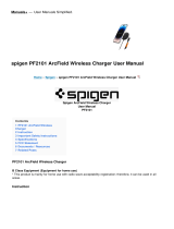
Figure 7. FRDM-KL25Z interface dongle
5.1.1 Connecting the FRDM-KL25Z communication interface board
A typical connection of the FRDM-KL25Z communication interface board to the
FRDMCD1020EVM evaluation board is done by directly stacking the FRDMCD1020EVM
on the Freedom/Arduino Interface connectors as shown in Figure 8.
Figure 8. FRDMCD1020EVM connection to the FRDM-KL25Z

NXP Semiconductors
KTFRDMCD1020EVMUG
FRDMCD1020EVM Evaluation Board
KTFRDMCD1020EVMUG All information provided in this document is subject to legal disclaimers. © NXP B.V. 2018. All rights reserved.
User guide Rev. 1 — 31 January 2018
13 / 26
5.2 KIT-SW33-EVB switch board (optional)
The optional KIT-SW33-EVB switch board is a fully populated switch board with 33
dip switches to allow closure to GND or battery voltage on the input channels. The
KIT-SW33-EVB switch board also provides a 36-pin interface connector to provide
easy access to all 22 input channels, including the input protection R/C network on the
FRDMCD1020EVM evaluation board. The KIT-SW33-EVM switch board connects to J16
on the FRDMCD1020EVM evaluation board as shown in Figure 9.
Figure 9. KIT-SW33-EVB interface with the FRDMCD1020EVM
Use switches SW1 and SW2 to connect or disconnect the SG pins to the
FRDMCD1020EVM ground, or an external voltage level set on the SW_SG test point.
Switches SW3, SW4, and SW5, allow connection to FRDMCD1020EVM ground/battery
and/or external voltage level applied to BATT_IN test point, as selected by J2. Ground
or battery level selection on the SP channels is done in three independent banks of four
channels each, controlled by SW6, SW7, and SW8 SPDT switches respectively.
The KIT-SW33-EVB switch board is compatible with other evaluation platforms. If the
signals on KIT-SW33-EVB are not used by FRDMCD1020EVM, ignore the corresponding
buttons. Refer to www.nxp.com/FRDMCD1020EVM on the Overview tab under Get
Started for the FRDMCDE1020EVM evaluation board schematic and the KIT-SW33-EVB
adapter board schematic.

NXP Semiconductors
KTFRDMCD1020EVMUG
FRDMCD1020EVM Evaluation Board
KTFRDMCD1020EVMUG All information provided in this document is subject to legal disclaimers. © NXP B.V. 2018. All rights reserved.
User guide Rev. 1 — 31 January 2018
14 / 26
6 Configuring the hardware
Figure 10 presents an example hardware configuration incorporating a PC, power
supply, the FRDMCD1020EVM evaluation kit boards and a KIT-SW33-EVB switch board.
The SPI communication traffic travels through a male-to-male USB cable (not shown)
between the PC and the FRDM-KL25Z communication board.
Figure 10. Example hardware configuration
6.1 Step-by-step hardware setup instructions to use SPIGen
To start working with the FRDMCD1020EVM, the following connections and setup must
be performed:
1. Mount the FRDMCD1020EVM on top of the FRDM-KL25Z communication board.
2. (Optional) If using the optional KIT-SW33-EVB switch board, mount the KIT-SW33-
EVB switch board to the J16 connector of the FRDMCD1020EVM evaluation board.
3. Plug the USB cable mini connector end into the FRDM-KL25Z communication board.
4. Plug the USB cable standard connector end into the computer.
5. With power turned off, attach a DC power supply to FRDMCD1020EVM.
6. Attach loads to the FRDMCD1020EVM board output terminals as desired.
7. Turn on the power supply. The LED labeled D5 lights up.

NXP Semiconductors
KTFRDMCD1020EVMUG
FRDMCD1020EVM Evaluation Board
KTFRDMCD1020EVMUG All information provided in this document is subject to legal disclaimers. © NXP B.V. 2018. All rights reserved.
User guide Rev. 1 — 31 January 2018
15 / 26
7 Software installation and setup
7.1 Installing SPIGen on your computer
The latest version of SPIGen is designed to run on any Windows 10, Windows 8 or
Windows 7 operating system. To download and install the software:
1. Go to http://www.nxp.com/SPIGEN.
2. On the Overview tab, select the Download button or click on the Downloads tab to
open the SPIGen Downloads page.
3. Select the software link for SPIGen 7.x.x or click the Download button next to the
software version.
4. Read the NXP Semiconductor Software Licence Agreement and select either
I Accept or Decline.
5. Click the I Accept button to open the SPIGen Software - Windows Application page.
The software package immediately begins downloading. If the software package does
not automatically download, click the Download button on this page.
6. Run the install program. The installation wizard guides the user through the rest of the
process.
7.2 Launching the SPIGen GUI on your computer
The SPIGen GUI provides embedded support for some NXP devices, eliminating the
need to load a configuration file to communicate with a specific device. CD1020 is
supported in the latest version of the SPIGen software. To launch and start using the
SPIGen software:
1. Locate the SPIGen program under Windows Start→Programs→SPIGen.
2. Click on the SPIGen icon. The SPI Generator GUI opens
3. Locate the CD1020 folder in the Device View window of the GUI.
4. Click to expand the CD1020 folder and view the CD1020 configuration registers.
7.3 SPIGen GUI interface overview
The SPIGen GUI is divided into three major sections:
• SPI Words: The SPI Words window provides the latest SPI word sent and received in
RAW format (32-bit).
• Device View: The Device View window provides a list of devices supported by the
SPIGen software.
• Command View: The Command View is the window area located to the right of
Device View. The Command View provides access to all functions and commands for
each CD1020 page in the Device View.

NXP Semiconductors
KTFRDMCD1020EVMUG
FRDMCD1020EVM Evaluation Board
KTFRDMCD1020EVMUG All information provided in this document is subject to legal disclaimers. © NXP B.V. 2018. All rights reserved.
User guide Rev. 1 — 31 January 2018
16 / 26
Figure 11. SPIGen GUI
7.4 Understanding the SPIGen GUI Interface
Before starting communication with the FRDMCD1020EVM, it is important to understand
the full duplex nature of the SPI communication protocol.
During each SPI clock cycle, a full duplex data transmission occurs:
• the master sends a bit on the MOSI line; the slave reads it from that same line
• the slave sends a bit on the MISO line; the master reads it from that same line
Not all transmissions require all four of these operations to be meaningful, but they do
happen. This means when the master sends a configuration command [A] through the
MOSI pin, the actual data received on the MISO pin is the value for the transaction made
in the previous SPI request. This in turns means the user sees the result to the command
[A] on the MISO response of the next SPI transaction [B], as depicted in Figure 12.
Figure 12. Full duplex SPI transaction example

NXP Semiconductors
KTFRDMCD1020EVMUG
FRDMCD1020EVM Evaluation Board
KTFRDMCD1020EVMUG All information provided in this document is subject to legal disclaimers. © NXP B.V. 2018. All rights reserved.
User guide Rev. 1 — 31 January 2018
17 / 26
Due to the full duplex nature of the protocol, when using the SPIGen GUI, the user
should send the command twice in order to see the actual response to the request sent.
7.4.1 Reading/writing an SPI register
The CD1020 SPI register map is confirmed by 26 functional registers which can
be read-only, write-only, or read and write. For more detail on the organization and
register definition, refer to the CD1020 Data Sheet. The SPIGen GUI provides an easy
way to configure and read each one of the registers. Figure 13 presents the Device
Configuration Register in the SPIGen GUI.
Figure 13. Register SPI write
To write a configuration register / command:
• Click on the corresponding command page
• Click to highlight and set the register bits to 1 or click to clear the highlight and set the
register bit to 0. Users may also select any available, pre-defined configuration options.
• Click the Write button to send the SPI command
To read the value of a specific register:
• Click the Read button twice.
The current value is populated on the raw register bits. The SPIGen GUI writes or reads
registers according to the register's properties. Therefore, if a register is read-only,
SPIGen does not provide a predefined way to write to that register. Figure 14 presents
the Read Status register, an example of a read-only register on the CD1020. Notice that
SPIGen displays only the Read button.

NXP Semiconductors
KTFRDMCD1020EVMUG
FRDMCD1020EVM Evaluation Board
KTFRDMCD1020EVMUG All information provided in this document is subject to legal disclaimers. © NXP B.V. 2018. All rights reserved.
User guide Rev. 1 — 31 January 2018
18 / 26
Figure 14. Read only register example
7.4.2 Creating sequential scripts
The SPIGen GUI provides a way to create, save and load scripts with a sequence
of commands for quick configuration. To add commands to the Sequential Script
Command page:
1. Select a device register from the Device View of the GUI.
2. In the Command View, set the configuration bits as desired.
3. In the Command View, click on the >Seq button
The configuration is added to the list of sequential commands in the Sequential Script
Command window in the order each configuration was entered, see Figure 15.
Figure 15. Sequential script command page
The sequential script command page organizes and creates various functions within the
script by using the functionality of the following buttons.
• Insert Wait: Inserts a defined delay before the next command
• Remove Selected line: Deletes the selected line from the script
• Move Up/Down: Shift the selected command one place up or down
• Clear List: Deletes all lines from the script window
• Insert Data 0 Toggle: Not Used on FRDMCD1020EVM

NXP Semiconductors
KTFRDMCD1020EVMUG
FRDMCD1020EVM Evaluation Board
KTFRDMCD1020EVMUG All information provided in this document is subject to legal disclaimers. © NXP B.V. 2018. All rights reserved.
User guide Rev. 1 — 31 January 2018
19 / 26
• Run: Starts the script as a single or loop sequence
• Loop: Enables the looping sequence mode to repeat the script indefinitely
• Stop: Ends the script before it is over
• Save: Saves the current configuration into a .txt file
• Load: Loads a previous configuration from a file
7.4.3 Sending customized SPI commands
The SPIGen GUI sends customized 32-bit SPI words for debugging or any other special
use with the CD1020.
Figure 16. Generic single command page
• From the Generic folder in the Device View, select the Single Command page.
• In the Command View:
– Using the Length in Bits radio buttons, choose the 32-bit length.
– SPIGen supports binary or hexadecimal number systems. Choose the radio button
for either Binary or Hex number system.
– Set any of the 32 bits to high or low as desired.
– Click the Send Once button or Send Continuously button to send the selected word
through SPI.
• The SPI Word Session Log frame, shows the history of commands sent. The SPI
Word Session Log has the following optional user specified choices:
– Click the Disable Logging box to improve performance.
– Click the Save button to save the session log to a file.
– Use the Clear button to erase the session log.
• The Extra pins area sets the extra control/data I/Os to high or low, as provided by
the FRDM-KL25Z I/O ports. Note that not all signals may be usable as input or output

NXP Semiconductors
KTFRDMCD1020EVMUG
FRDMCD1020EVM Evaluation Board
KTFRDMCD1020EVMUG All information provided in this document is subject to legal disclaimers. © NXP B.V. 2018. All rights reserved.
User guide Rev. 1 — 31 January 2018
20 / 26
with the FRDMCD1020EVM. Ensure your understanding of each pin function on the
CD1020 before applying high or low to these pins.
• The Quick Commands frame allows for the creation of customized commands. The
commands are saved for quick access during the current session. To save a quick
command:
1. Set the 32-bit word to be saved.
2. Enter a name on the header frame.
3. Click the Save button. Any new commands added are listed below the header
frame.
4. Use the Delete button to erase commands in the Quick Commands frame.
/