Figures and illustrations in this User Manual are provided for reference only and may differ from actual product appearance.
Product design and specifications may be changed without notice.
Instruction
This TV is provided with interactive functionality through a set-back box (SBB/STB) connected to the TV, and with other TVs in a computer-controlled
system for hotels and other hospitality businesses.
Interactive : When the TV is powered-up initially, it sends a command to identify the SBB/STB; if identified, theTV switches to ONLINE mode and full
control is through the SBB/STB.
If the TV is in ONLINE mode, it stops receiving IR(Samsung remote) commands and acts according to interface protocol.
Stand-Alone: If SBB/STB is not identified, the TV should be switched to STAND-ALONE mode with restricted operation.
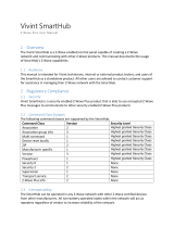
Operational Modes
When this TV (in Hotel mode) is operated with a SBB/STB, it is in one of two states :
• ONLINE or STAND-ALONE. In the STAND-ALONE state, the TV will act as a Hotel TV, but without active communication. This is to prevent guests
from trying to cheat the system by disconnecting the SBB/STB.
To set the details for Stand-alone or interactive mode, refer to pages 23-26(Setting the hotel option data : Stand-alone mode and Interactive mode)
• Some operations may be restricted to prevents guests from "cheating" the TV system.
• No main menu(Interactive mode) or Channel Menu, Plug & Play in Main Menu (Stand-Alone mode)
• Limited Volume and Panel key lock or unlock
Still image warning
Avoid displaying still images (like jpeg picture files) or still image element (like TV Program logo, panorama or 4:3 image format, stock or news bar at screen
bottom etc.) on the screen. Constant displaying of still picture can cause uneven wear of screen phosphor, which will affect image quality. To reduce risk of
this effect, please follow below recommendations:
• Avoid displaying the same TV channel for long periods.
• Always try do display any image on full screen, use TV set picture format menu for best possible match.
• Reduce brightness and contrast values to minimum required to achieve desired picture quality, exceeded values may speed up the burnout process.
• Frequently use all TV features designed to reduce image retention and screen burnout. Refer to the relevant user manual section for details.
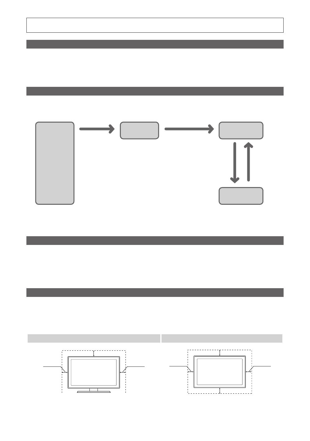
Securing the Installation Space
Keep required distances between the product and other objects (e.g. walls) to ensure proper ventilation.
Failing to do so may result in fire or a problem with the product due to an increase in the internal temperature.
✎
When using a stand or wall-mount, use parts provided by Samsung Electronics only.
x
Using parts provided by another manufacturer may result in a problem with the product or injuries due to the product falling.
✎
The appearance may differ, depending on the product.
Installation with a stand. Installation with a wall-mount.
10 cm10 cm
10 cm
10 cm10 cm
10 cm
10 cm
Power
ON
Hotel TV
Online Mode
Poll Rate 20/sec
Stand-alone
Mode
Hotel Mode On
SBB/STB Online if
one success within 10
attempts
SBB/STB
Online-10
consecutive
fails
SBB/STB
Status-
Attempt
every 2secs