
Arduino® Nano 33 IoT
1 / 18 Arduino® Nano 33 IoT Modified: 08/02/2022
Product Reference Manual
SKU: ABX00027
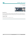
Description
Nano 33 IoT is a miniature sized module containing a Cortex M0+ SAMD21 processor, a WiFi+BT module based on
ESP32, a crypto chip which can securely store certificates and pre-shared keys and a 6 axis IMU. The module can
either be mounted as a DIP component (when mounting pin headers), or as a SMT component, directly soldering it
via the castellated pads.
Target areas:
Maker, enhancements, basic IoT application scenarios

Arduino® Nano 33 IoT
2 / 18 Arduino® Nano 33 IoT Modified: 08/02/2022
Features
SAMD21G18A
Processor
256KB Flash
32KB Flash
Power On Reset (POR) and Brown Out Detection (BOD)
Peripherals
12 channel DMA
12 channel event system
5x 16 bit Timer/Counter
3x 24 bit timer/counter with extended functions
32 bit RTC
Watchdog Time
CRC-32 generator
Full speed Host/Device USB with 8 end points
6x SERCOM (USART, I2C, SPI, LIN)
Two channel I2S
12 bit 350ksps ADC (up to 16 bit with oversampling)
10 bit 350ksps DAC
External Interrupt Controller (up to 16 lines)

Arduino® Nano 33 IoT
3 / 18 Arduino® Nano 33 IoT Modified: 08/02/2022
Nina W102
Module
Dual Core Tensilica LX6 CPU at up to 240MHz
448 KB ROM, 520KB SRAM, 2MB Flash
WiFi
IEEE 802.11b up to 11Mbit
IEEE 802.11g up to 54MBit
IEEE 802.11n up to 72MBit
2.4 GHz, 13 channels
16dBm output power
19 dBm EIRP
-96 dBm sensitivity
Bluetooth BR/EDR
Max 7 peripherals
2.4 GHz, 79 channels
Up to 3 Mbit/s
8 dBm output power at 2/3 Mbit/s
11 dBm EIRP at 2/3 Mbit/s
-88 dBm sensitivity
Bluetooth Low Energy
Bluetooth 4.2 dual mode
2.4GHz 40 channels
6 dBm output power
9 dBm EIRP
-88 dBm sensitivity
Up to 1 Mbit/
MPM3610 (DC-DC)
Regulates input voltage from up to 21V with a minimum of 65% efficiency @minimum load
More than 85% efficiency @12V
ATECC608A (Crypto Chip)
Cryptographic co-processor with secure hardware based key storage
Protected storage for up to 16 keys, certificates or data
ECDH: FIPS SP800-56A Elliptic Curve Diffie-Hellman
NIST standard P256 elliptic curve support
SHA-256 & HMAC hash including off-chip context save/restore
AES-128 encrypt/decrypt, galois field multiply for GCM

Arduino® Nano 33 IoT
4 / 18 Arduino® Nano 33 IoT Modified: 08/02/2022
LSM6DSL (6 axis IMU)
Always-on 3D accelerometer and 3D gyroscope
Smart FIFO up to 4 KByte based
±2/±4/±8/±16 g full scale
±125/±250/±500/±1000/±2000 dps full scale

Arduino® Nano 33 IoT
5 / 18 Arduino® Nano 33 IoT Modified: 08/02/2022
6
6
6
6
6
7
7
8
8
9
9
9
10
10
10
10
10
10
11
11
12
12
13
13
13
14
15
15
15
16
16
17
17
18
Contents
1 The Board
1.1 Application Examples
2 Ratings
2.1 Recommended Operating Conditions
2.2 Power Consumption
3 Functional Overview
3.1 Board Topology
3.2 Processor
3.3 WiFi/BT Communication Module
3.4 Crypto
3.5 IMU
3.6 Power Tree
4 Board Operation
4.1 Getting Started - IDE
4.2 Getting Started - Arduino Web Editor
4.3 Getting Started - Arduino IoT Cloud
4.4 Sample Sketches
4.5 Online Resources
4.6 Board Recovery
5 Connector Pinouts
5.1 USB
5.2 Headers
5.3 Debug
6 Mechanical Information
6.1 Board Outline and Mounting Holes
6.2 Connector Positions
7 Certifications
7.1 Declaration of Conformity CE DoC (EU)
7.2 Declaration of Conformity to EU RoHS & REACH 211 01/19/2021
7.3 Conflict Minerals Declaration
8 FCC Caution
9 Company Information
10 Reference Documentation
11 Revision History

Arduino® Nano 33 IoT
6 / 18 Arduino® Nano 33 IoT Modified: 08/02/2022
1 The Board
As all Nano form factor boards, Nano 33 IoT does not have a battery charger but can be powered through USB or
headers.
NOTE: Arduino Nano 33 IoT only supports 3.3V I/Os and is NOT 5V tolerant so please make sure you are not
directly connecting 5V signals to this board or it will be damaged. Also, as opposed to Arduino Nano boards that
support 5V operation, the 5V pin does NOT supply voltage but is rather connected, through a jumper, to the USB
power input.
1.1 Application Examples
Weather station: Using the Arduino Nano 33 IoT together with a sensor and a OLED display, we can create a small
weather station communicating temperature, humidity etc. directly to your phone.
Air quality monitor: Bad air quality may have serious effects on your health. By assembling the Nano 33 IoT, with
a sensor and monitor you can make sure that the air quality is kept in indoor-environments. By connecting the
hardware assembly to an IoT application/API, you will receive real time values.
Air drum: A quick and fun project is to create a small air drum. Connect your Nano 33 IoT and upload your sketch
from the Create Web Editor and start creating beats with your audio workstation of your choice.
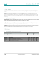
2 Ratings
2.1 Recommended Operating Conditions
Symbol Description Min Max
Conservative thermal limits for the whole board: -40 °C ( 40 °F) 85°C ( 185 °F)
2.2 Power Consumption
Symbol Description Min Typ Max Unit
VINMax Maximum input voltage from VIN pad -0.3 - 21 V
VUSBMax Maximum input voltage from USB connector -0.3 - 21 V
PMax Maximum Power Consumption - - TBC mW

Arduino® Nano 33 IoT
7 / 18 Arduino® Nano 33 IoT Modified: 08/02/2022
3 Functional Overview
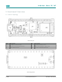
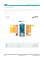
3.1 Board Topology
Board topology top
Ref. Description Ref. Description
U1 ATSAMD21G18A Controller U3 LSM6DSOXTR IMU Sensor
U2 NINA-W102-00B WiFi/BLE Module U4 ATECC608A-MAHDA-T Crypto Chip
J1 Micro USB Connector PB1 IT-1185-160G-GTR Push button
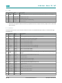
Board topology bottom

Arduino® Nano 33 IoT
8 / 18 Arduino® Nano 33 IoT Modified: 08/02/2022
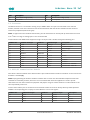
Ref. Description Ref. Description
Ref. Description Ref. Description
SJ1 Open solder bridge (VUSB) SJ4 Closed solder bridge (+3V3)
TP Test points xx Lorem Ipsum
3.2 Processor
The Main Processor is a Cortex M0+ running at up to 48MHz. Most of its pins are connected to the external
headers, however some are reserved for internal communication with the wireless module and the on-board
internal I2C peripherals (IMU and Crypto).
NOTE: As opposed to other Arduino Nano boards, pins A4 and A5 have an internal pull up and default to be used
as an I2C Bus so usage as analog inputs is not recommended.
Communication with NINA W102 happens through a serial port and a SPI bus through the following pins.
SAMD21 Pin SAMD21 Acronym NINA Pin NINA Acronym Description
13 PA08 19 RESET_N Reset
39 PA27 27 GPIO0 Attention Request
41 PA28 7 GPIO33 Acknowledge
23 PA14 28 GPIO5 SPI CS
21 GPIO19 UART RTS
24 PA15 29 GPIO18 SPI CLK
20 GPIO22 UART CTS
22 PA13 1 GPIO21 SPI MISO
21 PA12 36 GPIO12 SPI MOSI
31 PA22 23 GPIO3 Processor TX Nina RX
32 PA23 22 GPIO1 Processor RX Nina TX
3.3 WiFi/BT Communication Module
Nina W102 is based on ESP32 and is delivered with a pre-certified software stack from Arduino. Source code for the
firmware is available [9].
NOTE: Reprogramming the wireless module’s firmware with a custom one will invalidate compliance with radio
standards as certified by Arduino, hence this is not recommended unless the application is used in private
laboratories far from other electronic equipment and people. Usage of custom firmware on radio modules is the
sole responsibility of the user.
Some of the module’s pins are connected to the external headers and can be directly driven by ESP32 provided
SAMD21’s corresponding pins are aptly tri-stated. Below is a list of such signals:
SAMD21 Pin SAMD21 Acronym NINA Pin NINA Acronym Description
48 PB03 8 GPIO21 A7
14 PA09 5 GPIO32 A6
8 PB09 31 GPIO14 A5/SCL
7 PB08 35 GPIO13 A4/SDA

Arduino® Nano 33 IoT
9 / 18 Arduino® Nano 33 IoT Modified: 08/02/2022
3.4 Crypto
The crypto chip in Arduino IoT boards is what makes the difference with other less secure boards as it provides a
secure way to store secrets (such as certificates) and accelerates secure protocols while never exposing secrets in
plain text.
Source code for the Arduino Library that supports the Crypto is available [10]
3.5 IMU
Arduino Nano 33 IoT has an embedded 6 axis IMU which can be used to measure board orientation (by checking
the gravity acceleration vector orientation) or to measure shocks, vibration, acceleration and rotation speed.
Source code for the Arduino Library that supports the IMU is available [11]
3.6 Power Tree

Arduino® Nano 33 IoT
10 / 18 Arduino® Nano 33 IoT Modified: 08/02/2022
Power tree
4 Board Operation
4.1 Getting Started - IDE
If you want to program your Arduino 33 IoT while offline you need to install the Arduino Desktop IDE [1] To connect
the Arduino 33 IoT to your computer, you’ll need a Micro-B USB cable. This also provides power to the board, as
indicated by the LED.
4.2 Getting Started - Arduino Web Editor
All Arduino boards, including this one, work out-of-the-box on the Arduino Web Editor [2], by just installing a simple
plugin.
The Arduino Web Editor is hosted online, therefore it will always be up-to-date with the latest features and support
for all boards. Follow [3] to start coding on the browser and upload your sketches onto your board.
4.3 Getting Started - Arduino IoT Cloud
All Arduino IoT enabled products are supported on Arduino IoT Cloud which allows you to Log, graph and analyze
sensor data, trigger events, and automate your home or business.
4.4 Sample Sketches
Sample sketches for the Arduino 33 IoT can be found either in the “Examples” menu in the Arduino IDE or in the
“Documentation” section of the Arduino Pro website [4]
4.5 Online Resources
Now that you have gone through the basics of what you can do with the board you can explore the endless
possibilities it provides by checking exciting projects on ProjectHub [5], the Arduino Library Reference [6] and the
online store [7] where you will be able to complement your board with sensors, actuators and more

Arduino® Nano 33 IoT
11 / 18 Arduino® Nano 33 IoT Modified: 08/02/2022
4.6 Board Recovery
All Arduino boards have a built-in bootloader which allows flashing the board via USB. In case a sketch locks up the
processor and the board is not reachable anymore via USB it is possible to enter bootloader mode by double-
tapping the reset button right after power up.
5 Connector Pinouts
Pinout

Arduino® Nano 33 IoT
12 / 18 Arduino® Nano 33 IoT Modified: 08/02/2022
5.1 USB
Pin Function Type Description
1 VUSB Power Power Supply Input. If board is powered via VUSB from header this is an Output
(1)
2 D- Differential USB differential data -
3 D+ Differential USB differential data +
4 ID Analog Selects Host/Device functionality
5 GND Power Power Ground
1. The board can support USB host mode only if powered via the VUSB pin and if the jumper close to the VUSB
pin is shorted.
5.2 Headers
The board exposes two 15 pin connectors which can either be assembled with pin headers or soldered through
castellated vias.
Pin Function Type Description
1 D13 Digital GPIO
2 +3V3 Power Out Internally generated power output to external devices
3 AREF Analog Analog Reference; can be used as GPIO
4 A0/DAC0 Analog ADC in/DAC out; can be used as GPIO
5 A1 Analog ADC in; can be used as GPIO
6 A2 Analog ADC in; can be used as GPIO
7 A3 Analog ADC in; can be used as GPIO
8 A4/SDA Analog ADC in; I2C SDA; Can be used as GPIO (1)
9 A5/SCL Analog ADC in; I2C SCL; Can be used as GPIO (1)
10 A6 Analog ADC in; can be used as GPIO
11 A7 Analog ADC in; can be used as GPIO
12 VUSB Power
In/Out
Normally NC; can be connected to VUSB pin of the USB connector by shorting a
jumper
13 RST Digital In Active low reset input (duplicate of pin 18)
14 GND Power Power Ground
15 VIN Power In Vin Power input
16 TX Digital USART TX; can be used as GPIO
17 RX Digital USART RX; can be used as GPIO
18 RST Digital Active low reset input (duplicate of pin 13)
19 GND Power Power Ground
20 D2 Digital GPIO
21 D3/PWM Digital GPIO; can be used as PWM
22 D4 Digital GPIO
23 D5/PWM Digital GPIO; can be used as PWM
24 D6/PWM Digital GPIO, can be used as PWM
25 D7 Digital GPIO
26 D8 Digital GPIO

Arduino® Nano 33 IoT
13 / 18 Arduino® Nano 33 IoT Modified: 08/02/2022
Pin Function Type Description
27 D9/PWM Digital GPIO; can be used as PWM
28 D10/PWM Digital GPIO; can be used as PWM
29 D11/MOSI Digital SPI MOSI; can be used as GPIO
30 D12/MISO Digital SPI MISO; can be used as GPIO
5.3 Debug
On the bottom side of the board, under the communication module, debug signals are arranged as 3x2 test pads
with 100 mil pitch. Pin 1 is depicted in Figure 3 – Connector Positions
Pin Function Type Description
1 +3V3 Power Out Internally generated power output to be used as voltage reference
2 SWD Digital SAMD11 Single Wire Debug Data
3 SWCLK Digital In SAMD11 Single Wire Debug Clock
4 UPDI Digital ATMega4809 update interface
5 GND Power Power Ground
6 RST Digital In Active low reset input
6 Mechanical Information
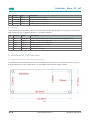
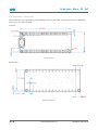
6.1 Board Outline and Mounting Holes
The board measures are mixed between metric and imperial. Imperial measures are used to maintain a 100 mil
pitch grid between pin rows to allow them to fit a breadboard whereas board length is Metric.
Layout

Arduino® Nano 33 IoT
14 / 18 Arduino® Nano 33 IoT Modified: 08/02/2022
6.2 Connector Positions
The view below is from top however it shows Debug connector pads which are on the bottom side. Highlighted
pins are pin 1 for each connector’
Top view:
Top side connectors
Bottom view:
Bottom side connectors

Arduino® Nano 33 IoT
15 / 18 Arduino® Nano 33 IoT Modified: 08/02/2022
7 Certifications
7.1 Declaration of Conformity CE DoC (EU)
We declare under our sole responsibility that the products above are in conformity with the essential requirements
of the following EU Directives and therefore qualify for free movement within markets comprising the European
Union (EU) and European Economic Area (EEA).
7.2 Declaration of Conformity to EU RoHS & REACH 211 01/19/2021
Arduino boards are in compliance with RoHS 2 Directive 2011/65/EU of the European Parliament and RoHS 3
Directive 2015/863/EU of the Council of 4 June 2015 on the restriction of the use of certain hazardous substances in
electrical and electronic equipment.
Substance Maximum limit (ppm)
Lead (Pb) 1000
Cadmium (Cd) 100
Mercury (Hg) 1000
Hexavalent Chromium (Cr6+) 1000
Poly Brominated Biphenyls (PBB) 1000
Poly Brominated Diphenyl ethers (PBDE) 1000
Bis(2-Ethylhexyl} phthalate (DEHP) 1000
Benzyl butyl phthalate (BBP) 1000
Dibutyl phthalate (DBP) 1000
Diisobutyl phthalate (DIBP) 1000
Exemptions : No exemptions are claimed.
Arduino Boards are fully compliant with the related requirements of European Union Regulation (EC) 1907 /2006
concerning the Registration, Evaluation, Authorization and Restriction of Chemicals (REACH). We declare none of
the SVHCs (https://echa.europa.eu/web/guest/candidate-list-table), the Candidate List of Substances of Very High
Concern for authorization currently released by ECHA, is present in all products (and also package) in quantities
totaling in a concentration equal or above 0.1%. To the best of our knowledge, we also declare that our products
do not contain any of the substances listed on the "Authorization List" (Annex XIV of the REACH regulations) and
Substances of Very High Concern (SVHC) in any significant amounts as specified by the Annex XVII of Candidate list
published by ECHA (European Chemical Agency) 1907 /2006/EC.

Arduino® Nano 33 IoT
16 / 18 Arduino® Nano 33 IoT Modified: 08/02/2022
7.3 Conflict Minerals Declaration
As a global supplier of electronic and electrical components, Arduino is aware of our obligations with regards to
laws and regulations regarding Conflict Minerals, specifically the Dodd-Frank Wall Street Reform and Consumer
Protection Act, Section 1502. Arduino does not directly source or process conflict minerals such as Tin, Tantalum,
Tungsten, or Gold. Conflict minerals are contained in our products in the form of solder, or as a component in
metal alloys. As part of our reasonable due diligence Arduino has contacted component suppliers within our supply
chain to verify their continued compliance with the regulations. Based on the information received thus far we
declare that our products contain Conflict Minerals sourced from conflict-free areas.
8 FCC Caution
Any Changes or modifications not expressly approved by the party responsible for compliance could void the user’s
authority to operate the equipment.
This device complies with part 15 of the FCC Rules. Operation is subject to the following two conditions:
(1) This device may not cause harmful interference
(2) this device must accept any interference received, including interference that may cause undesired operation.
FCC RF Radiation Exposure Statement:
1. This Transmitter must not be co-located or operating in conjunction with any other antenna or transmitter.
2. This equipment complies with RF radiation exposure limits set forth for an uncontrolled environment.
3. This equipment should be installed and operated with minimum distance 20cm between the radiator &
your body.
English: User manuals for license-exempt radio apparatus shall contain the following or equivalent notice in a
conspicuous location in the user manual or alternatively on the device or both. This device complies with Industry
Canada license-exempt RSS standard(s). Operation is subject to the following two conditions:
(1) this device may not cause interference
(2) this device must accept any interference, including interference that may cause undesired operation of the
device.
French: Le présent appareil est conforme aux CNR d’Industrie Canada applicables aux appareils radio exempts de
licence. L’exploitation est autorisée aux deux conditions suivantes :
(1) l’ appareil nedoit pas produire de brouillage
(2) l’utilisateur de l’appareil doit accepter tout brouillage radioélectrique subi, même si le brouillage est susceptible
d’en compromettre le fonctionnement.
IC SAR Warning:
English This equipment should be installed and operated with minimum distance 20 cm between the radiator and
your body.
French: Lors de l’ installation et de l’ exploitation de ce dispositif, la distance entre le radiateur et le corps est d ’au
moins 20 cm.

Arduino® Nano 33 IoT
17 / 18 Arduino® Nano 33 IoT Modified: 08/02/2022
Important: The operating temperature of the EUT can’t exceed 85℃ and shouldn’t be lower than -40℃.
Hereby, Arduino S.r.l. declares that this product is in compliance with essential requirements and other relevant
provisions of Directive 2014/53/EU. This product is allowed to be used in all EU member states.
Frequency bands Maximum output power (ERP)
863-870Mhz -3.22dBm
9 Company Information
Company name Arduino SA.
Company Address Via Ferruccio Pelli 14 6900 Lugano Switzerland
10 Reference Documentation
Reference Link
Arduino IDE
(Desktop) https://www.arduino.cc/en/Main/Software
Arduino IDE (Cloud) https://create.arduino.cc/editor
Cloud IDE Getting
Started
https://create.arduino.cc/projecthub/Arduino_Genuino/getting-started-with-arduino-
web-editor-4b3e4a
Forum http://forum.arduino.cc/
SAMD21G18 http://ww1.microchip.com/downloads/en/devicedoc/40001884a.pdf
NINA W102 https://www.u-blox.com/sites/default/files/NINA-W10_DataSheet_%28UBX-
17065507%29.pdf
ECC608 http://ww1.microchip.com/downloads/en/DeviceDoc/40001977A.pdf
MPM3610 https://www.monolithicpower.com/pub/media/document/MPM3610_r1.01.pdf
NINA Firmware https://github.com/arduino/nina-fw
ECC608 Library https://github.com/arduino-libraries/ArduinoECCX08
LSM6DSL Library https://github.com/stm32duino/LSM6DSL
ProjectHub https://create.arduino.cc/projecthub?by=part&part_id=11332&sort=trending
Library Reference https://www.arduino.cc/reference/en/
Arduino Store https://store.arduino.cc/

Arduino® Nano 33 IoT
18 / 18 Arduino® Nano 33 IoT Modified: 08/02/2022
11 Revision History
Date Revision Changes
04/15/2021 1 General datasheet updates
-
 1
1
-
 2
2
-
 3
3
-
 4
4
-
 5
5
-
 6
6
-
 7
7
-
 8
8
-
 9
9
-
 10
10
-
 11
11
-
 12
12
-
 13
13
-
 14
14
-
 15
15
-
 16
16
-
 17
17
-
 18
18


Ask a question and I''ll find the answer in the document
Finding information in a document is now easier with AI
Related papers
-
Arduino ABX00030 User manual
-
Arduino ABX00031 User manual
-
Arduino ABX00062 User manual
-
Arduino MKR SD Proto Shield Schematics
-
Arduino ABX00049 User manual
-
-
-
Arduino UNO R3 User manual
-
-
Arduino Portenta C33 User manual
Other documents
-
ecarPlug ECRF232C User manual
-
MICROCHIP DV161001 Operating instructions
-
u-blox NINA-W15 series System Integration Manual
-
Infineon CY8CKIT-028-SENSE User guide
-
-
Cypress Semiconductor CY8CKIT-062-WiFi-BT User manual
-
 Industrial Shields 007001000700 Operating instructions
-
 Industrial Shields 007001000400 Operating instructions
-
Panasonic ENW49D01AZKF User manual
-
 Industrial Shields 007001000800 User manual


