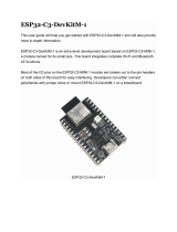
Panasonic ENW49D01AZKF is an embedded Wi-Fi module based on the Espressif® ESP32-S2. It features a 2.4 GHz Wi-Fi 802.11 b/g/n interface, a Xtensa® single-core 32-bit LX7 microprocessor, and a rich set of peripherals, including GPIOs, I²C, SPI, UART, and ADC. The module is designed for low-power applications and has a deep sleep mode with a power consumption of less than 100 µA. It is also highly integrated, with built-in QSPI Flash and PSRAM memory, making it easy to develop and deploy applications.
Possible use cases for the Panasonic ENW49D01AZKF include:
- IoT devices: The module can be used to connect IoT devices to the internet, enabling them to send and receive data wirelessly.
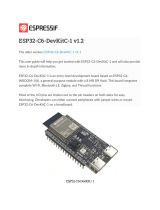


-
 1
1
-
 2
2
-
 3
3
-
 4
4
-
 5
5
-
 6
6
-
 7
7
-
 8
8
-
 9
9
-
 10
10
-
 11
11
-
 12
12
-
 13
13
-
 14
14
-
 15
15
-
 16
16
-
 17
17
-
 18
18
-
 19
19
-
 20
20
-
 21
21
-
 22
22
-
 23
23
-
 24
24
-
 25
25
-
 26
26
-
 27
27
-
 28
28
-
 29
29
-
 30
30
-
 31
31
-
 32
32
-
 33
33
-
 34
34
-
 35
35


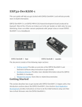
Panasonic ENW49D01AZKF is an embedded Wi-Fi module based on the Espressif® ESP32-S2. It features a 2.4 GHz Wi-Fi 802.11 b/g/n interface, a Xtensa® single-core 32-bit LX7 microprocessor, and a rich set of peripherals, including GPIOs, I²C, SPI, UART, and ADC. The module is designed for low-power applications and has a deep sleep mode with a power consumption of less than 100 µA. It is also highly integrated, with built-in QSPI Flash and PSRAM memory, making it easy to develop and deploy applications.
Possible use cases for the Panasonic ENW49D01AZKF include:
- IoT devices: The module can be used to connect IoT devices to the internet, enabling them to send and receive data wirelessly.
Ask a question and I''ll find the answer in the document
Finding information in a document is now easier with AI
Other documents
-
KeeYees ESP32 User manual
-
 MOUSER ELECTRONICS ESP32-C3-DevKitM-1 User guide
-
 Espressif ESP32-C6-DevKitC-1 v1.2 Operating instructions
-
 Espressif Systems ESP32-DevKitM-1 User manual
-
Arduino MKR SD Proto Shield Schematics
-
EEPROM CH341A 24 25 Series User manual
-
ezlo ic Home App User manual
-
Arduino UNO R3 User manual
-
-


